Abstract
Microfluidics typically uses channels to transport small objects by actuation forces such as an applied pressure difference or thermocapillarity. We propose that acoustic streaming is an alternative means of directional transport at small scales. Microbubbles on a substrate establish well controlled fluid motion on very small scales; combinations (“doublets”) of bubbles and microparticles break the symmetry of the motion and constitute flow transport elements. We demonstrate the principle of doublet streaming and describe the ensuing transport. Devices based on doublet flow elements work without microchannels and are thus potentially cheap and highly parallelizable.
Fluid mechanics on the micrometer scale has enjoyed much attention recently, not only because of the desire to incorporate fluids devices such as pumps or valves into microelectromechanical systems (1, 2), but also because of the potential applications in biomedicine and bioengineering. The flow of liquid in these devices is regulated by a large variety of applied forces (3), such as pressure differences, electrophoresis (4), capillary forces (5), or Marangoni forces (6). In biology-related applications, the flows are often used for cytometry and sorting of cells (7–9). In the overwhelming majority of microfluidic setups, the flow is confined to microchannels or microcapillaries that have been etched into or grafted onto a substrate.
Among the many methods of driving liquid through microdevices, not much work has been devoted to acoustics (ultrasound). At first glance, acoustics is an unpromising candidate for micromanipulation, because the wavelength of even high-frequency ultrasound is not much below 1 mm, whereas microelectromechanical systems need to control processes on the submillimeter scale. Acoustic actuation has been proposed before in a device containing millimetric piezoelectric elements (10). The flow is created in the bulk fluid by the attenuation of sound, causing a momentum transfer to the liquid. This method relies on high-frequency ultrasound (50 MHz in ref. 10) to obtain a significant attenuation. This method cannot induce flows on micrometer scales and leads to significant heating of the liquid, a result which is often undesirable.
However, there is an agent that focuses ultrasonic energy down to the micrometer scale: microbubbles. When a bubble is driven by an ultrasonic wave, even one whose wavelength is much larger than the bubble radius a, its oscillatory response is substantially confined to a region of size ≈a. This is true for violent, inertial bubble collapses that lead to cavitation damage (11) or sonoluminescence (12), but it is also true for weakly oscillating bubbles that set up a characteristic flow field in the liquid around them (13).
The use of bubbles in microfluidic devices has been demonstrated, e.g., by Prosperetti and coworkers (14, 15), who generated vapor bubbles to achieve pumping action in microchannels. In other work, the rapid expansion of a vapor bubble provides a transient force to switch valves in a microdevice (16). Electrolysis is another way to generate gas bubbles acting as transient pistons and valves (17). Displaced bubbles can also block the path of a light beam, creating an optical switch (18).
In the present article, we investigate the potential of ultrasound-driven gas bubbles as actuators for steady microfluidic flow. In contrast to previous bubble applications, the position and volume of the microbubbles do not change significantly, and the induced flow is not a consequence of the time-periodic bubble expansion but a steady streaming flow on the micrometer scale.
We have investigated potential applications of this “microacoustic” approach in the field of biomedicine. Earlier research had shown that cell walls can be rendered permeable for large molecules by insonation with ultrasound if microbubbles are present (19, 20). Drug delivery and gene transfection had been accomplished in this way, but the precise interaction between oscillating or collapsing bubbles and cells had not been identified. Micrometer-scale acoustic streaming has been proposed as a possible mechanism for membrane permeation: high shear rates submit the cells to strong stresses (21).
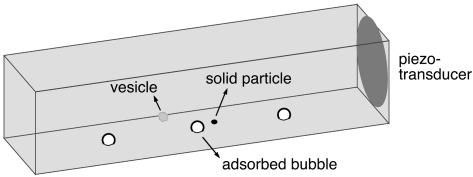
To study this possible cell permeation mechanism in a controlled fashion, we developed a setup (Fig. 1) for direct microscopic observation of the interaction between single bubbles and single lipid vesicles (“artificial cells” with a lipid membrane of well defined mechanical properties). A small quartz cuvette of dimensions 10 × 10 × 50 mm (Hellma, Müllheim, Germany) is filled with a suspension of vesicles or cells. A piezoelectric transducer (1 mm thick; PIC 151 ceramic from Physik Instrumente, Karlsruhe/Palmbach, Germany) at the wall excites an ultrasonic field in the cuvette at frequencies ranging from 40 to 200 kHz. Microbubbles (radius a ∼ 10–100 μm), generated by squirting air into the cuvette, adhere to its bottom and are driven to oscillations by the ultrasound. The ultrasonic pressures we use are small (<<105 Pa), so that the bubbles respond with linear oscillations, rather than violent cavitation collapses.
Fig. 1.
Layout of the experiment. The piezoelectric transducer generates a standing ultrasound field in the cuvette, which directly excites microbubbles adsorbed at the bottom and indirectly leads to streaming flow around solid particles. An inverted microscope with phase-contrast capability observes the ensuing flow and the motion of suspended vesicles or cells from below, through the use of a high-speed camera.
The giant lipid vesicles we use (radius R ∼ 10–100 μm) consist of a single bilayer of DOPC phospholipids (dioleoylphosphatidylcholine, Sigma) grown by electroformation (22). The optical contrast is enhanced by growing the vesicles in a 0.3 M sucrose solution, then transferring them to a glucose solution of equal osmolarity. A mixture of glycerol and water, in volume ratio 2:1 and viscosity 20 times that of water, was used as solvent. The bubbles and liquid flow were observed from below with an inverted phase-contrast microscope (Zeiss Axiovert 25CFL). Rapid motion was captured with a high-speed camera operating at 250 frames per second (Kodak Imager).
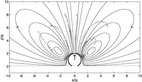
A main result of our previous work (23) is that reproducible, steady-flow currents are set up by the oscillating bubbles. This leading-order nonlinear effect is known as RNW (Rayleigh–Nyborg–Westervelt) streaming (24). The vesicles follow the streamlines of this flow as almost passive tracers: their centers of mass are translated with the liquid, and their outline is deformed according to the shear stress in the flow acting over scales of R. The flow around a single bubble consists of vortex loops (closed streamlines) in a plane perpendicular to the substrate (Fig. 2). As a vesicle follows a loop, it is deformed by shear forces and can even be ruptured (23) (P.M. and S.H., unpublished work). Note that the bubble streaming reported here is quite different in flow pattern from that induced by an oscillating solid object (25), such as the cylinders used in a recent application of acoustic streaming in chemical microreactors (26). The biological relevance of acoustic streaming on larger (centimeter) scales is well established (27).
Fig. 2.
Streaming field around a bubble adsorbed at a wall, obtained from the Stokes singularity theory (solid lines). The large arrow indicates the leading-order singularity representing the bubble: a point force oriented perpendicular to the wall. Some experimental trajectories of vesicles are overlaid onto the simulation, showing qualitative agreement.
We also found that the acoustic streaming flow in our experiments has small streaming Reynolds number (23), so that it can be quantitatively described by a finite number of Stokes flow singularities (28). Because of the presence of the wall close to the oscillating bubble, the singularities representing the bubble motion, located at b = (0, 0, a) (Fig. 2), have to be supplemented by image singularities located at bI = (0,0,-a) (29). Formally, the flow field induced by the bubble can we written as
 |
[1] |
where u0 = ε2aω is the streaming velocity scale of a bubble oscillating with angular frequency ω and amplitude εa. Δφ is the phase shift between the radial and translational oscillations of the bubble (recently, we took ultra-high-speed movies verifying that typically Δφ ≈ 20°).  ,
,  , and
, and  are dimensionless Green`s functions of point force, dipole, and (a projection of) hexadecapole singularities placed at the bubble center, taking into account the presence of a wall. Explicit expressions for all of these contributions are found in refs. 28 and 30 (P.M. and S.H., unpublished work). The leading-order term is the stokeslet Green's function (the flow induced by a point force, such as a small particle falling in a liquid):
 |
[2] |
The presence of one stokeslet singularity (described by Sij in the bulk) at the bubble center (r = x - b) near the wall induces three image singularities at the image position (r′ = x - bI), namely a stokeslet, a dipole  , and a stokeslet doublet
  (28). The standoff distance of the bubble center to the wall is called hb here. The subtraction sign is valid for j = z (stokeslet perpendicular to the wall), and the addition sign is valid for a stokeslet parallel to the wall. The flow field (2) fulfills no-slip boundary conditions at the wall, as does the complete flow (1), whose streamline pattern is shown in Fig. 2.
The far-field characteristic of this flow is dominated by that of  , derived from Eq. 2 for r ≫ r′ >> a, which results in
 |
[3] |
for the radial flow component, decreasing as 1/r3 at large distances r from the center of the bubble. Fig. 2 demonstrates that the actually measured trajectories of the vesicles follow vortex loops, as predicted by theory. The slight discrepancy in the position of the vortex center (located at an angle with respect to the bubble center ≈15° larger than calculated) is due to the fact that the vesicles, although ≈10 times smaller than the bubble in this case, are not perfect passive tracer particles. Their size is not negligible compared to the length scale of velocity variations near the bubble, and their presence gives rise to acoustic effects such as an additional streaming flow component induced at the vesicle boundary. Very recent results suggest that the use of even smaller tracer particles (fluorescent beads of R = 1 μm) results in a much better quantitative agreement with theory (J.-P. Raven, P.M., and S.H., unpublished data).
We now propose a method to obtain modified streaming flows, shifting the focus from inducing deformation and rupture of cells or vesicles to transporting these objects over the substrate, a first step toward a microfluidic device useful, e.g., in cytometry. Microbubbles can be used for this purpose as well: The bubble oscillation induces a streaming flow not only around itself, but also around any other object nearby, in particular a solid particle at a position p. Amin and Riley (25) calculated this Stokes flow and concluded that its leading-order singularity is another point force (stokeslet) flow, but now with the force oriented parallel to the wall (Fig. 3) rather than perpendicular
 |
[4] |
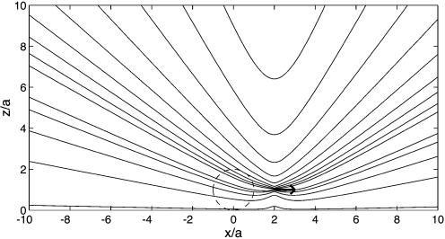
where L is the distance between the centers of bubble and particle and ap is the radius of the solid particle (assumed to be spherical). The distance parameter is D = L/ap, and  is the flow generated by a unit point force parallel to the wall, with coordinates relative to the particle position (rp = x - p). This calculation shows that the strength of the flow induced by the particle relative to that of the bubble is s = 3/8 × (a/L)4D3/(D2 - 1)2 × 2/sin(Δφ). Such a parallel stokeslet flow field, shown in Fig. 3, is very different from that of Fig. 2. The far-field behavior for radial flow derived from Eq. 4 is
 |
[5] |
with hp as the standoff distance of the particle center from the wall. Note that the decay for large rp ≫ r is now ∝1/r2, rather than the 1/r3 in Eq. 3. The relative strength, s, of the bubble and particle streaming flows crucially depends on L; the closer the two objects are, the stronger is the particle streaming flow.
Fig. 3.
Stokes flow of a point force singularity oriented parallel to the wall (arrow), positioned at p = (2a,0, a). This is the leading-order RNW (Rayleigh–Nyborg–Westervelt) streaming flow induced around a small particle at p by an oscillating bubble (dashed circle) located at b = (0, 0, a).
The presence of a solid object has profound consequences for the overall steady-flow field, which is the superposition of the bubble and particle streaming fields: (i) the cylindrical flow field symmetry is broken, (ii) the streamlines are not closed anymore, and (iii) the far-field decay is now dominated by the 1/r2 behavior of the stokeslet parallel to the wall, increasing the reach of the flow field.
The flow field of the bubble/particle combination (which we shall call a doublet) is easily obtained in the present small scale regime, where inertial forces are negligible compared to viscous forces (Stokes regime). The superposition principle allows for linear combination of the flow fields generated by different sources, here the bubble and the particle. As a first approximation, we do not take into account the deformation of the particle streamlines induced by the finite size of the bubble (where the bubble streaming actually is dominant). The streamlines are computed from the integration of the doublet flow field  by using a Runge–Kutta–Fehlberg algorithm. For given initial conditions, the streamline shape depends only on the relative strength, s, of the constituent flow fields.
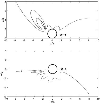
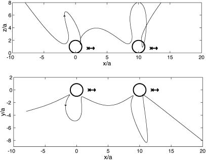
An example calculation of a (three-dimensional) streamline of the complete streaming field is shown in Fig. 4. The circle and arrow represent the bubble and particle, respectively. On the bubble side of the doublet, the streamline vortex loops are still discernible. A spiraling motion leads the streamline around the bubble, and the radial amplitude is damped. Close to the particle, the streamline revolves around the particle position until asymptoting toward a streamline of the far field shown in Fig. 3.
Fig. 4.
A streamline in the streaming flow induced by a bubble–particle doublet, viewed from the side (Upper) and the top (Lower). The arrow indicates the position p = (2a,0, hp) of the stokeslet parallel to the wall, where hp/a = 0.75 and the stokeslet strength is s = 0.15 times that of the vertical stokeslet induced by the bubble.
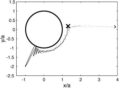
The characteristics of doublet streaming can be observed when a suspended particle approaches a bubble attached to the wall. Fig. 5 shows a large bubble that has “caught” a quartz particle, which remains almost stationary (vibrating slightly) at one of the stagnant flow positions of the pure bubble flow field (Fig. 2). The stationary position of the particle is reminiscent of recent work on the self-organization of much larger particles (0.8 mm in diameter) in a vibrated liquid (31) (that flow is, however, not driven by bubbles, and is characterized by different streaming patterns). A doublet is thus formed. Fig. 6 shows an experimentally observed trajectory (dashed) of a vesicle that approaches this doublet. Indeed, the small vesicle undergoes just the sequence of events simulated by the trajectory in Fig. 4: it bounces off the bubble, is transported around, and is then expelled on the particle side of the doublet, where it leaves the field of view. A second, larger vesicle, whose trajectory is also shown in Fig. 6, gets too close to the particle itself, where the shear forces tear it apart (cross in Fig. 6). Images of this event can be seen in Fig. 5: the ruptured vesicle material is ejected from the doublet as a jet of liquid (arrows in Fig. 5) with a velocity and direction that agrees with the simulations of the doublet singularities. The agreement remains qualitative, both because of missing experimental information (hp could not be measured) and approximations in the theory [the particle is not a sphere, but disk-shaped, and its distance from the bubble is small enough to result in significant contributions from higher-order terms in Amin and Riley's (25) formalism].
Fig. 5.
A bubble (large circular object; a ≈ 80 μm) and a quartz particle (small, bright object near the center; ap ≈ 20 μm) form a streaming doublet with L ≈ 105 μm. A vesicle (arrows; R ≈ 10 μm) follows the streamlines of the doublet flow and is ruptured upon close encounter with the particle (Right). With these parameters, we infer the ratio of particle stokeslet and bubble stokeslet strengths to be s ≈ 0.15. This number, as well as the estimated standoff distance hp/a ≈ 0.75, was used for the simulation in Fig. 4. The images were taken at t = 0, 0.3, and 0.5 sec; taking into account the oscillatory character of the trajectory (Fig. 6), an average transport speed of ≈1 mm/sec results.
Fig. 6.
Top view of experimental trajectories of vesicles in the streaming flow of the bubble–particle doublet of Fig. 5. A small vesicle is directionally transported beyond the particle (dashed line trajectory). A larger vesicle (continuous line trajectory), that displayed in Fig. 5, is ruptured near the position of the particle (cross).
We have thus established that directional motion of micrometer-sized vesicles in steady streaming flow is possible. The controlled break-up of the vesicle in Fig. 5 (at a well defined position induced by a well controlled flow field) suggests a direct application in cell homogenization (32), where the desire is a gentle, controlled opening of the cell wall to release cell or- ganelles of smaller scale without destroying them.
At lower acoustic intensity, rupture events should cease altogether and transport will be dominant. To move cells or vesicles over larger distances, several doublets could pass the objects on to each other. A simulation of the flow generated by two adjacent doublets with parallel orientations (Fig. 7) shows that the fluid particles are indeed “handed over” from bubble to bubble. The same will then happen to any approximately passive tracer particle or substance.
Fig. 7.
Streamline in the flow induced by a succession of two aligned doublets, viewed from the side (Upper) and the top (Lower). Both doublets are of the same type as that in Fig. 4.
The integration of doublets in microfluidic devices is a natural next step, which could be achieved by various experimental designs. We propose a simple solution involving two construction elements: small patches of hydrophobic material on a hydrophilic substrate, and etched protrusions of the substrate (Fig. 8). Bubbles will preferentially attach to the patches, and the protrusions play the role of the particles in the doublet simulations discussed above. Because of the capillary pressure inside a bubble, micrometer-sized bubbles tend to lose gas to the surrounding liquid by diffusion. For bubbles larger than a few micrometers and liquid saturated with air, this process is slow compared to the transport time scales considered here. For smaller bubbles, the loss of gas is counteracted by the oscillation itself: at sufficiently large driving amplitude, the net effect of oscillatory motion is a net gain of gas over a cycle. This process is called rectified diffusion and can be used to achieve a stable equilibrium bubble size (33).
Fig. 8.
Schematic of structural elements for a bubble microfluidics device. A hydrophilic substrate is etched away to leave small, ≈10- to 50-μm protrusions. Hydrophobic patches with a diameter of ≈10–100 μm (e.g., gold or Teflon) are then deposited next to the protrusions to accommodate the microbubbles and form a doublet.
The simulations indicate that it is not essential for the transport whether the particle is attached to the substrate or not. An alternative design would have holes instead of the hydrophobic patches, so that gas can be added or removed from below, allowing for an active control of bubble size. Etching, milling of holes, and wettability patterning are standard techniques today (34–36) and should pose no problem for the suggested sizes of patches and particles of several tens of micrometers. We currently investigate these and similar designs in collaboration with A. van den Berg (University of Twente and MESA+ Center for Micro- and Nanotechnology).
How do microacoustic devices using bubble–particle doublets compare to more “conventional” microfluidic microelectromechanical systems? The most striking feature of our bubble-driven design is that it operates in bulk liquid and does not need microchannels. The relatively large bulk liquid volume is disadvantageous if the liquid processed is valuable (as in some lab-on-a-chip applications). When the medium is inexpensive, however, forgoing microchannels makes the device significantly simpler and cheaper. Without having to etch a large number of microchannels, such a device can easily process a large number of cells or similar microobjects through many parallel transport lines, applying the same forces to each of the objects. Moreover, microchannels or microcapillaries may be clogged by suspended particles (37), which is not an issue here. The speed of transport can be varied easily and interactively by changing amplitude and frequency of the ultrasound. The velocities achievable here (at least several millimeters per second) compare favorably with the highest typically achieved in other microfluidic devices (38). Larger driving pressure amplitudes will increase the obtainable velocities further.
The most promising applications for bubble-driven microfluidics lie in the manipulation of biological materials, such as in cell sorting, cell fusion, or vesicle fusion. Microbubbles provide not only an effective transport mechanism but at the same time exert large localized shear forces whenever the transported object comes near a bubble. As these forces are sufficient to open pores in lipid membranes (23), drug delivery or gene transfection simultaneous to transport becomes possible. An application close at hand and discussed before is gentle, controlled cell homogenization (32).
Acknowledgments
We thank A. van den Berg and H. Gardeniers for numerous discussions and their willingness to take this project to the level of application in the future; Jan-Paul Raven for help with the computation of streamlines; and Detlef Lohse for encouragement and support of this project.
This paper was submitted directly (Track II) to the PNAS office.
References
- 1.Unger, M. A., Chou, H.-P., Thorsen, T., Sherer, A. & Quake, S. R. (2000) Science 288, 113-116. [DOI] [PubMed] [Google Scholar]
- 2.Beebe, D. J., Moore, J. S., Yu, Q., Liu, R. H., Kraft, M. L., Jo, B.-H. & Devadoss, C. (2000) Proc. Natl. Acad. Sci. USA 97, 13488-13493. [DOI] [PMC free article] [PubMed] [Google Scholar]
- 3.Stone, H. & Kim, S. (2001) AIChE J. 47, 1250-1254. [Google Scholar]
- 4.Harrison, D. J., Fluri, K., Seiler, K., Fan, Z., Effenhauser, C. S. & Manz, A. (1993) Science 261, 895-897. [DOI] [PubMed] [Google Scholar]
- 5.Walker, G. M. & Beebe, D. J. (2002) Lab Chip 2, 131-134. [DOI] [PubMed] [Google Scholar]
- 6.Kataoka, D. E. & Troian, S. (1999) Nature 402, 794-797. [Google Scholar]
- 7.Sohn, L. L., Saleh, O. A., Facer, G. R., Beavis, A. J., Allan, R. S. & Notterman, D. A. (2000) Proc. Natl. Acad. Sci. USA 97, 10687-10690. [DOI] [PMC free article] [PubMed] [Google Scholar]
- 8.Gawad, S., Schild, L. & Renaud, P. (2001) Lab Chip 1, 76-82. [DOI] [PubMed] [Google Scholar]
- 9.Meldrum, D. R. & Holl, M. R. (2002) Science 297, 1197-1198. [DOI] [PubMed] [Google Scholar]
- 10.Rife, J. C., Bell, M. I., Horwitz, J. S., Kabler, M. N., Auyeung, R. C. Y. & Kim, W. J. (2000) Sens. Actuator A 86, 135-140. [Google Scholar]
- 11.Leighton, T. G. (1994) The Acoustic Bubble (Academic, London).
- 12.Brenner, M. P., Hilgenfeldt, S. & Lohse, D. (2002) Rev. Mod. Phys. 74, 425-484. [Google Scholar]
- 13.Brennen, C. E. (1995) Cavitation and Bubble Dynamics (Oxford Univ. Press, Oxford).
- 14.Yuan, H. & Prosperetti, A. (1999) J. Micromech. Microeng. 9, 402-413. [Google Scholar]
- 15.Geng, X., Yuan, H., Oguz, H. N. & Prosperetti, A. (2001) J. Micromech. Microeng. 11, 270-276. [Google Scholar]
- 16.Papavasiliou, A. P., Liepmann, D. & Pisano, A. P. (1999) Proc. ASME–MEMS Int. Mech. Eng. Congr. Expo. 1, 435-440.16387405 [Google Scholar]
- 17.Papavasiliou, A., Pisano, A. P. & Liepmann, D. (2001) Proc. 11th Int. Conf. Solid State Sens. Actuators, 940-943.
- 18.Jackel, J. L., Johnson, J. J. & Tomlinson, W. J. (1990) Opt. Lett. 15, 1470-1472. [DOI] [PubMed] [Google Scholar]
- 19.Tachibana, K., Uchida, T., Ogawa, K., Yamashita, N. & Tamura, K. (1999) Lancet 353, 1409. [DOI] [PubMed] [Google Scholar]
- 20.Miller, D. L. & Quddus, J. (2000) Ultrasound Med. Biol. 26, 661-667. [DOI] [PubMed] [Google Scholar]
- 21.Rooney, J. A. (1970) Science 169, 869-871. [DOI] [PubMed] [Google Scholar]
- 22.Dimitrov, D. S. & Anguelova, M. I. (1987) Prog. Colloid Polym. Sci. 73, 48-56. [Google Scholar]
- 23.Marmottant, P. & Hilgenfeldt, S. (2003) Nature 423, 153-156. [DOI] [PubMed] [Google Scholar]
- 24.Lighthill, J. (1978) J. Sound Vib. 61, 391-418. [Google Scholar]
- 25.Amin, N. & Riley, N. (1990) J. Fluid Mech. 210, 459-473. [Google Scholar]
- 26.Lutz, B. R., Chen, J. & Schwartz, D. T. (2003) Proc. Natl. Acad. Sci. USA 100, 4395-4398. [DOI] [PMC free article] [PubMed] [Google Scholar]
- 27.Shi, X., Martin, R. W., Vaezy, S. & Crum, L. A. (2002) J. Acoust. Soc. Am. 111, 1110-1121. [DOI] [PubMed] [Google Scholar]
- 28.Pozrikidis, C. (1992) Boundary Integral and Singularity Methods for Linearized Viscous Flow (Cambridge Univ. Press, Cambridge, U.K.).
- 29.Blake, J. R. & Chwang, A. T. (1974) J. Eng. Math. 8, 23-29. [Google Scholar]
- 30.Longuet-Higgins, M. S. (1998) Proc. R. Soc. London Ser. A 454, 725-742. [Google Scholar]
- 31.Voth, G. A., Bigger, B., Buckley, M. R., Losert, W., Brenner, M. P., Stone, H. A. & Gollub, J. P. (2002) Phys. Rev. Lett. 88, 234301. [DOI] [PubMed] [Google Scholar]
- 32.Steck, T. L. (1972) Membrane Isolation, eds. Fox, C. F. & Keith, A. E. (Sinauer Associates, Stamford, CT), pp. 76-114.
- 33.Hilgenfeldt, S., Lohse, D. & Brenner, M. P. (1996) Phys. Fluids 8, 2808-2826. [Google Scholar]
- 34.Kenis, P. J. A., Ismagilov, R. F. & Whitesides, G. M. (1999) Science 285, 83-85. [DOI] [PubMed] [Google Scholar]
- 35.Zhao, B., Moore, J. S. & Beebe, D. J. (2001) Science 291, 1023-1026. [DOI] [PubMed] [Google Scholar]
- 36.Thorsen, T., Maerkl, S. J. & Quake, S. R. (2002) Science 298, 580-584. [DOI] [PubMed] [Google Scholar]
- 37.Shelby, J. P., White, J., Ganesan, K., Rathod, P. K. & Chiu, D. T. (2003) Proc. Natl. Acad. Sci. USA 100, 14618-14622. [DOI] [PMC free article] [PubMed] [Google Scholar]
- 38.Whitesides, G. M. & Stroock, A. D. (2001) Phys. Today 54, 42-48. [Google Scholar]


