Abstract
Echo Planar Imaging (EPI) is the standard pulse sequence used in fast diffusion-weighted magnetic resonance imaging (MRI), but is sensitive to susceptibility-induced inhomogeneities in the main B0 magnetic field. In diffusion MRI of the human head, this leads to geometric distortion of the brain in reconstructed diffusion images, and a lack of correspondence with undistorted high-resolution MRI scans that are used to define the subject anatomy. In this study, we have tested an approach to estimate and correct this distortion of using a non-linear registration framework based on mutual-information. We use the commonly acquired anatomical image as the registration-template and constrain the registration using spatial regularization and physics-based information about the characteristics of the distortion, but without requiring any additional data collection. Results are shown for simulated and experimental data.
I. Introduction
Diffusion MRI is a non-invasive technique which helps to quantify the micro-strcutural characteristics of the underlying tissue and can be used to study the anatomical connections between different parts of the brain. It provides information about underlying white-matter fiber structure by in-vivo mapping of diffusion process in human head [1], [2]. Clinically, it is useful for study and diagnosis of neurological disorders and conditions like stroke [3].
Most diffusion MRI uses EPI pulse sequence for data collection. EPI is a popular fast imaging technique, but EPI images are well-know to have localized geometric distortion, in practice, caused by main B0 magnetic field inhomogeneities [4], [5]. Distortion is most significant near the interfaces between air, bone, and soft tissues, due to large magnetic susceptibility differences between them [6]. Diffusion analysis often require mapping the diffusion weighted images to commonly acquired undistorted anatomical Ti weighted images. The errors in the mapping due to the distortion of diffusion data can lead to misalignment by several millimeters and can also lead to unreliable tractography [7], [8], which can limit the accuracy of image analysis in the affected regions.
Most approaches to distortion correction rely on acquiring additional data to provide an accurate model of the distortion, such as direct mapping of the B0 field inhomogeneity [9], [5], measuring the point spread function [10], or collecting two or more EPI image with different phase-encode direction [11], [12]. These methods can be effective, but all require additional information which is not acquired in a large fraction of imaging studies and the additional acquisition could be time consuming.
Another class of methods is based on registration and use the information in undistorted anatomical images to estimate the distortion in EPI images [6], [13], [14], [15], [16], [17], [18]. In these methods, the anatomical structural images are used as registration template while EPI images are warped to match the template in a non-rigid registration framework. Another feature of this problem is that the diffusion images have very different contrast than the standard anatomical scans to which they are registered. This necessitates the use of pre-processing to ensure that the images are similar enough to be registered using optimization metrics based on pixel-wise differences between the two images [13], [14], [15], [16], or optimization metrics like mutual information that are insensitive to differences in image contrast [6], [17], [18].
In this work, we perform constrained non-rigid registration using mutual information to correct the distortion. This approach only requires the diffusion images and an undistorted anatomical image, without the need to acquire any additional calibration. Due to the nature of susceptibility-induced distortion [4], we constrain the deformation in two ways. First, we allow the deformation only along phase-encode direction of EPI image. Second, we constrain the deformation to be smooth by adding spatial regularization. During the registration, we also account for the accumulation or dispersion of MR signal due to distortion by modifying the intensity of the EPI image. We use undistorted anatomical T1 weighted image as registration template and diffusion images as the floating image in the registration framework.
Similar techniques have been used previously to correct EPI distortion. Studholme et al. [6] used MI with physics-constraints (but no spatial regularization) to correct functional-MRI images. Others [17], [18] have used spatial regularization (but no physics-constraints) to correct EPI diffusion images. Our approach combines these two constraints to obtain superior results to using either one individually.
This paper is organized as follows. Section II describes the characteristics of geometric distortion in EPI images. Section III describes our proposed registration framework for correcting this distortion. Section IV presents results on simulated and experimental data. Finally, discussion and conclusions are presented in Section V.
II. Distortion in Echo Planar Imaging
In the presence of a homogeneous B0 field, MRI encodes images by manipulating magnet gradient fields to setup a linear correspondence between spatial position in the image and the Fourier-domain frequency of the measured MRI data. B0 field inhomogeneity disrupts this linear correspondence, such that standard EPI images ρe(xe, ye) are approximately related to their ideal, undistorted version ρ(x, y) according to the following relationship [6]:
| (1) |
where, EPI coordinate (xe, ye) is related to undistorted coordinate (x, y) as:
| (2) |
| (3) |
and |J(xe, ye)| is the Jacobian of the coordinate transformation, which describes the intensity changes in the EPI images. We have assumed that x and y are EPI readout and phase-encoding direction respectively. Here, ΔB0(x, y) is the field inhomogeneity, Tes is the echo-spacing, τ is the duration of phase-encode gradient Gy, and Gx is the readout gradient.
Equations (2) and (3) shows that the distortion is present in both readout and phase-encode direction. The term in (3) scales the distortion in phase-encode direction, typically by order of magnitude as compared to distortion in readout direction. In real scenarios, the distortion in readout direction is limited to sub-millimeter where as in phase-encode direction it could be in order of 10-15 millimeters in a ected regions. This could lead to huge misalignment along the phase encode direction but practically no distortion along readout direction. Hence, in this work, similar to [6], we neglect the distortion along readout direction and approximate the Jacobian term as following:
| (4) |
III. Proposed Framework
Further, the intensity of the EPI images have to modified during the registration Due to the nature of the imaging physics, susceptibility-induced distortion has certain specific characteristics [4]. The geometric distortions a ect the image locally in a non-linear fashion, which makes rigid and affine registration methods insufficient.
Additionally, in contrast to the numerical gradient computation approach in Studholme et al. [6], we use analytic gradients for e cient optimization of registration cost function. It helps to converge to optimum solution faster and better than the numerical gradients, as in [6], even with large distortions. Unlike [6], we have also included a three-dimensional smoothing criteria in the cost function based on thin-plate spline bending energy. This regularization helps to add spatial information to the cost function and ensures that the registration process is stable even with large distortions. For estimation of joint pdf we used Parzen-window method with cubic B-spline as the window to give smoother and more realistic estimate of joint density [19]. This helps to avoid local minimum during optimization of the registration cost function.
The correction of a distorted EPI image Fe using anatomical image Fa requires (a) estimation of the deformation and (b) correction of intensity using the estimated deformation. The deformation is estimated by finding a transformation ϕ(Xa) : Xa ↦ Xe which warps the image from EPI coordinate Xe to anatomical image coordinate Xa. Using (1) and (4), we get the intensity-corrected EPI image Fw as following:
| (5) |
Then the corrected EPI image Fc, in the anatomical image coordinates, can be then expressed as
| (6) |
Our proposed method seeks to correct image distortion by optimizing the following cost-function,
| (7) |
where, ϕ is the spatial warping operator, I(Fa; Fc) is an energy term that encourages correspondence between the warped image Fc and the target image Fa, while (ϕ) is a regularization term.
We use normalized mutual information (NMI) as the measure of image alignment. Mutual information (MI) is measure of information shared between two communication channels or two images in our case. Since, both diffusion and structural images are acquired for same subject, after registration the images should be aligned in a way such that they contain maximum information about each other. This corresponds to finding a deformation which maximizes the mutual information between the images [20]. Since, MI does not make any assumption about the nature of the image content, it can be used in a multi-modal registration framework [21]. Studholme et al. [22] showed that mutual information is sensitive to image overlap and can increase with decreasing image overlap (and increasing misregistration). They proposed NMI as a ‘normalized’ measure which is less sensitive to changes in overlap. The normalized mutual information of the two images Fa and Fc is given by
| (8) |
where, H(Fa) and H(Fc) is the marginal entropy of the images, and H(Fa, Fc) is the joint entropy computed from the joint probability density p(m, n) of the images as following:
| (9) |
| (10) |
| (11) |
where, the marginal probability densities are calculated from the joint density by integrating out the other variable.
The transformation ϕ(Xa) has a two components in it – a rigid transformation ϕR(Xa) due to movement or change in the position of head in between two scans and a non-rigid transformation ϕΔB0 (Xa) due to the B0 field inhomogeneity.
| (12) |
We model the non-rigid deformation by 3D free-form deformation (FFD) based on cubic B-spline [23], [24]. It produces a smooth and locally controlled transformation. It is described by outer product of 1D cubic B-splines:
| (13) |
where, is the lth basis function of cubic B-spline [25] and Φi,j,k is the 3D mesh of control points with uniform spacing δ. (i,j,k) is the index of control points: . u, v, and w are the local re-parametrization of the location Xa with respect to the control points: . We use a single layer of phantom control-points at all ends to make the deformation well behaved by interpolating the end control-points [25]. In order to constrain the deformation only in the direction of phase-encode, the control points are constrained to change only y-coordinate while solving eq.(7). So, effectively only y-coordinate of the control points are the registration parameters.
Contrary to Studholme et al. [6], we have also included a regularization term (ϕ) to penalize over-fitting during the registration. This regularization plays an important role when the images have complementary contrast in non-rigid registration framework. Mutual information based similarity measure lacks spatial information of the intensities in the images because its only based on the joint distribution. But in MR image, intensities varies smoothly spatially and the intensities of neighboring voxels are not independent of each other. This makes similarity measures based only on mutual information unreliable, specially in non-rigid registration framework [26], [27], [28].
Further, since the magnetic field inhomogeneity variations are governed by Maxwell's equations, we know that the field variations will be generally smooth. Hence, we used 2-D bending energy of thin-metal plate for regularization as given by [29]. This regularization ensures the smoothness and invertibility of the transformation and does not penalize any rigid transformations. *** TO BE MODIFIED ***
| (14) |
We formulate our NMI based cost function (7) as a continuous and differentiable function of registration parameters. This requires a continuous joint histogram, which is estimated using a separable Parzen-window approach [19]. This takes the form
| (15) |
where V is the region of overlap and h is the Parzen-window (chosen to be a cubic B-spline in our implementation). A continuous joint histogram allows explicit analytic form of derivative of our cost function. As compared to numerical gradients, analytical gradients are more accurate and thus can lead to better algorithm performance.
Our choice of cubic B-spline as parzen window h(t) is motivated by its partition of unity property and the local support [25]. While, local support helps to reduce the computation, partition of unity plays an important role in simplifying the expression of marginal density and analytical gradient (16). Similar to [30], [31], we computed the expression for partial derivative with respected to ith registration parameter ψi,y (y-coordinate of control point) in our 1D non-rigid framework as:
| (16) |
where, A(ϕ) and B(ϕ) are expressed in (8) and,
| (17) |
where, α = Card(V ). The last term in (17) is the product of B-spline basis functions similar to that of in (13). Detailed steps of the derivation of (17) are given in [30].
Implementation
The whole registration framework was implemented in a multi-resolution pyramid to help avoid local minimum during the optimization of the cost function [30]. The input images were initially blurred using a Gaussian smoothing kernel and were down-sampled to a coarse resolution. The B-spline control points were initially serperated by 30 mm to estimate larger global deformation. The rigid part of the transformation ϕR from (12) was initially estimated using rigid registration with mutual information as described in [22]. Then the non-rigid part of the transformation ϕΔB0 was estimated as described above. After performing the registration on a coarse resolution grid, the registration grid was successively refined till it reached the initial resolution of image. Each grid refinement was also accompanied by introducing new B-spline control points, using Lane-Riesenfeld Algorithm [32], between exisiting control points to effectively reduce the spacing between them. This helps to capture the detailed deformation at finer resolution. A total of four grid refinement steps were used. We used simple gradient-descent method with decreasing step size to optimize our cost function.
Interpolation is an important and necessary step to reflect any non-cartesian displacement of voxels during optimization of cost function. We choose to use tri-linear interpolation on a densely sampled grid. This decision was made because our approach had the least effect on estimation of joint density. Interpolation techniques has been known to have effect on the final results in mutual-information based registration methods [33], [34]. It has been showed that tri-linear interpolation maximizes mutual-information at non-Cartesian grid positions due to the blurring introduced by the interpolation. Tsao et al. [34] suggested to use nearest-neighbor (NN) interpolation with random jitter to avoid the problem. But, in our problem it became in-effective as the deformations were subvoxel in many regions and use of NN interpolation could not capture this small deformation for further refinement of the alignment. We found that tri-linear interpolation on a densely sampled image worked better than NN interpolation, as the densely sampled image is itself a smooth representation of the original image and hence, practically, the information lost by blurring by use of tri- linear interpolation does not affect the mutual-information calculations. In this work, we sampled all the images on a grid which was three times denser than the original grid to reduce interpolation artifact.
IV. Results
A. Simulation
For simulation, we acquired the field-map of a brain scan along with standard anatomical images on a 3T Siemens Magnetom TrioTim scanner. MPRAGE scan (TE=3.09ms, TR=2530ms) at a resolution of 1.0×1.0×1.0 mm3 was used as the registration template. We also acquired T2 weighted data (TE=88ms, TR=10000ms) at a resolution of 0.8×0.8×3.5 mm which we used for the simulation. The field map was estimated from two gradient echo images with different echo times [35], with TE=10.00ms and 12.46ms (TR=1300ms for both) at a resolution of 2.0×2.0×2.0 mm3. Field map estimation was performed using a simplified version of the regularized estimation framework and graph-cut algorithm described in [36]. All the scans were sampled on the sampling grid of the field-map for simulation. The T2 weighted data was then distorted by adding phase (obtained from acquired field-map) in its fourier domain before reconstruction, as described in [4], [6]. This distorted image was then used as the ‘synthetic’ EPI image for the whole sequence. For purpose of simulation we set the parameters such that effective distortion was similar to distortion in common diffusion images. Here, we use the displacements as computed by the field-map, as in (3), as gold standard.
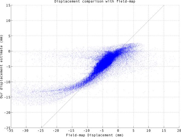
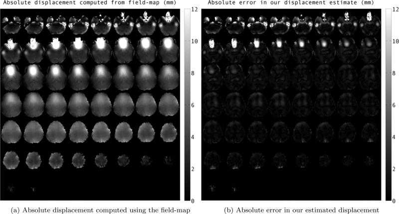
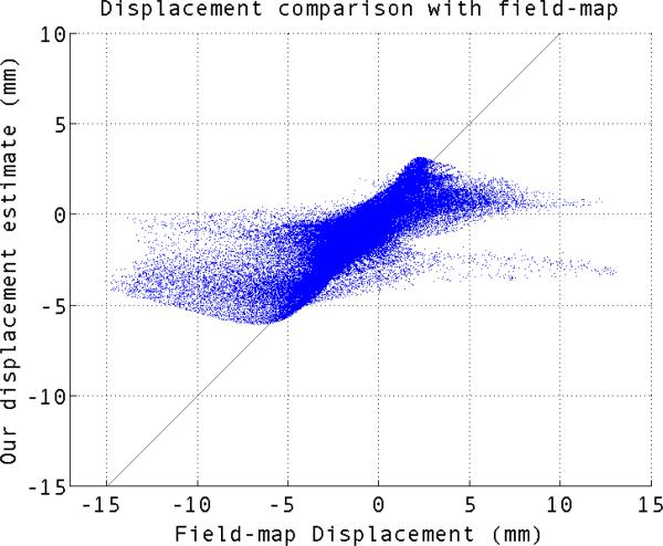
We compared the displacement estimated by our method to that of field map in Fig. 1 and 2. For perfect estimation the scatter plot should lie on a 45 degree line. Our estimated displacement follows a closely the 45 degree line for most of the voxels, although there are deviations. Most of the voxels which are off the 45 degree line lie very near to areas known to have very rapid supseptibility changes, where large amount of distortion makes the signal recovery and distortion correction particularly challenging. It can be seen in fig. 2a.
Fig. 1.
Scatter plot of our estimated displacement vs the field-map displacement for simulated EPI image.
Fig. 2.
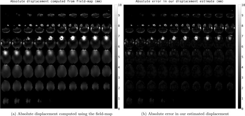
Mosaic images showing comparison of estimated displacement for simulated-EPI image in phase-encode direction using our method to that of field-map at different slices. The values are reported in milimeters.
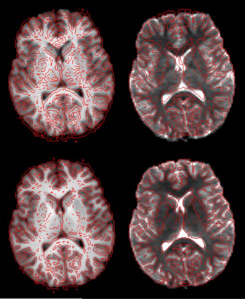
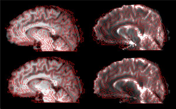
Fig. 2 shows the comparison of estimated displacement using our method to the displacement computed by the field-map, eq. (3). Absolute value of the field-map displacement (in mm) are shown in Fig. 2a. We have shown the absolute value of error in displacement estimation using our method in Fig. 2b. From the images we can see that estimate using the registration framework is close to field-map estimate within 1-2 milimeters, except in areas lying right next to sinuses, an area of rapid supseptibility change. Fig. 4 and fig. 3 show two slices of the simulated EPI images before and after the correction using registration framework. After distortion correction, the diffusion images are much better aligned with the anatomical image.
Fig. 4.
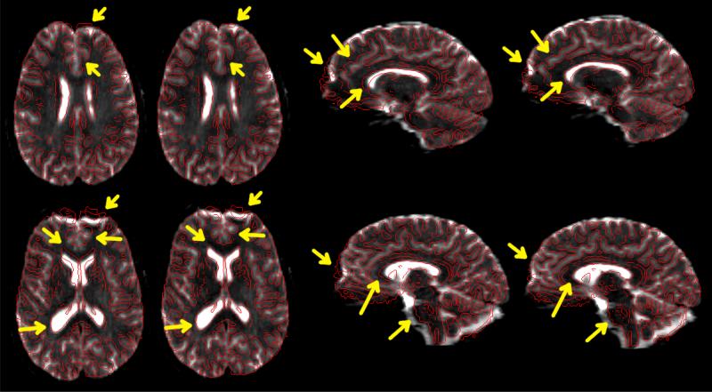
Overlay of an axial slice before and after correction of the distortion in simulated EPI sequence. First row shows image before distortion correction, while images after correction are presented in second row. First column shows the MPRAGE overlaid by the edge-map (in red) generated from b=0 image. Second column is converse to the first column (edge-map of MPRAGE superimposed on b=0 image).
Fig. 3.
Overlay of a saggital slice before and after correction of the distortion in simulated EPI sequence (similar to fig. 4). First row shows image before distortion correction, while images after correction are presented in second row. First column shows the MPRAGE overlaid by the edge-map (in red) generated from b=0 image. Second column is converse to the first column (edge-map of MPRAGE superimposed on b=0 image).
B. Imaging experiment
We tested our approach on data-set acquired as a part of imaging experiment. A 64-direction diffusion (single-shot EPI) scan (TE=88ms, TR=10000ms, b=1000s/mm2) was acquired at a resolution of 2.0×2.0×2.0 mm3. Along with diffusion weighted images, one image without any diffusion weighting (b=0s/mm2) was also acquired for the sequence. The b=0 image was used as the distorted EPI image for the correction. Standard MPRAGE image (TE=3.04ms, TR=2530ms) at a resolution of 1.0×1.0×1.0 mm3 was also acquired to be used as registration template. To analyze the effectiveness of the method, we also acquired the fieldmap (estimated from two gradient echo images using [36], with TE=10.00ms and 12.46ms, TR=1100ms for both) at a resolution of 2.0×2.0×2.0 mm3.
The proposed algorithm was used to correct the distorted diffusion data. Since, all the diffusion weighted images suffer from same static field inhomogeneity, we used just one of image, b=0 image for estimating the distortion. Among all the diffusion images, b=0 image has most consistent contrast throughout white matter and gray matter, as there is no diffusion encoding. MPRAGE has also consistent contrast throughout white matter and Gray matter, although complementary to b=0 image. Hence, b=0 image is the most suitable among all diffusion image for registration. Fig. 5 shows few slices of b=0 image before and after the correction, overlaid by the edge-map of MPRAGE. As expected, regions in frontal lobe are more affected by field inhomogeneity due to the presence of sinus. It can be seen that sub-cortical structures near ventricles get aligned after the correction. This also aligns the white-matter structures in a much better way.
Fig. 5.
Results after correction of the distortion in diffusion data. Image on the left-side of each pair shows the distorted b=0 image overlaid by edge-map of MPRAGE. The corrected image is shown on the right. Major differences are higlighted by arrows.
We also compared our estimate of displacement with that of as computed by the acquired field-map in fig. 6. It can been seen that our approach can estimate displacement within an error of 1-2 milimeters except in areas next to sinues. The scatter plot in fig. 7 shows that displacement in most of the voxels in our estimate follows the 45-degree line.
Fig. 6.
Comparison of our estimated displacement in phase-encode direction to that of field-map at different slices. The values are reported in milimeters.
Fig. 7.
Scatter plot of our estimated displacement vs the field-map displacement for diffusion data.
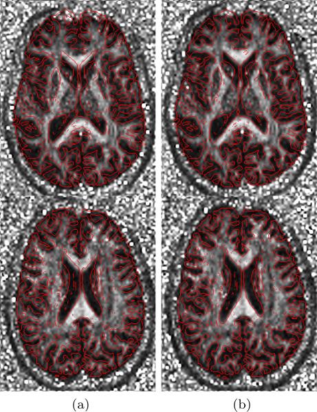
Furthermore, we studied the effect of distortion correction on the diffusion measures like Fractional Anisotropy (FA) etc, which are widely used in many neurological studies. Better alignment of diffusion images, and hence the diffusion measures, to the anatomical images can allow more reliable and useful analysis in any study. We estimated the deformation in b=0 image using the registration framework and then used the same deformation to correct all the diffusion images. The corrected set of diffusion images were then used to estimate the diffusion tensors at each voxel. FA images were generated from the eigenvalues and eigenvectors of the estimated tensors. Fig. 8 shows FA images before and after the correction overlaid by edge-map of MPRAGE. It can be clearly seen that the white matter regions are much better aligned after the correction. It is most evident in frontal areas near the ventricles.
Fig. 8.
FA images before and after the correction of diffusion data. (a) shows different slices of the distorted FA image overlaid by edge-map of MPRAGE. (b) shows the FA image after correction.
V. Discussion & Conclusion
In this paper, we addressed the common problem of distortion in images acquired using EPI sequences. We proposed a method which does not require acquisition of any special data-set, like field-map, or does not depend of field-models on tissue segmented image. Instead, we used the geometrically correct anatomical images, which is commonly acquired in most of the diffusion experiment, in a non-rigid registration framework based on the mutual-information measures to estimate the distortion. We used the physics of the distortion to constrain the registration process. The proposed approach accurately aligns the diffusion images to anatomical image. The accuracy of the correction is similar to that of when using field-maps. Though, we presented the results using a diffusion experiment, the techniques remains general and can be used with any EPI image, even with significantly different contrast as compared to structural image.
***BS, SVREG, population ***
The proposed technique has some known drawbacks. The areas which are distorted can be aligned accurately with help of anatomical image, but the structure lost due to the superposition of signal from different regions can not be recovered without any additional knowledge. This can be seen in severely distorted regions like lower frontal regions. However, the lost structure can also be not recovered by use of field-map based techniques without addition data or prior information. Further, in some areas near air/tissue boundary main magnetic field changes very rapidly resulting in severely distorted image. This rapid change can not be a modeled due to the small number of B-spline control points. By decreasing the spacing between the control points in the areas which are severely deformed, we can model the rapid changes in magnetic field. This increases the complexity of the algorithm and we will explore the irregular spacing of control points for the B-spline in the future. Another, drawback is that the proposed method required skull-stripped MPRAGE for better alignment. There are many automated skull-stripping algorigthm available in different neurological softwares, which can be used for this purpose.
In conclusion, the proposed technique shows an improvement in the alignment of diffusion EPI images to the anatomical images over traditional affine and rigid registration without need of field-map acquisition. This can be particularly useful for data-set which has been already acquired without field-map. The results so far indicates that the technique could be useful for many studies in brain-imaging.
References
- 1.Jones DK. Diffusion MRI: Theory, Methods, and Applications. Oxford University Press, Inc.; 2011. [Google Scholar]
- 2.Johansen-Berg H, Behrens TE. Diffusion MRI: from Quantitative Measurement to in-vivo Neuroanatomy. Academic Press; 2009. [Google Scholar]
- 3.Kantarci K, Avula R, Senjem M, Samikoglu A, Zhang B, Weigand S, Przybelski S, Edmonson H, Vemuri P, Knopman D, Ferman T, Boeve B, Petersen R, Jack C. Dementia with lewy bodies and alzheimer disease: Neurodegenerative patterns characterized by dti. Neurology. 2010;74(22):1814–1821. doi: 10.1212/WNL.0b013e3181e0f7cf. [DOI] [PMC free article] [PubMed] [Google Scholar]
- 4.Andersson JLR, Skare S. Jones DK, editor. Image distortion and its correction in diffusion MRI. Diffusion MRI: Theory, Methods, and Applications. 2010 [Google Scholar]
- 5.Jezzard P, Balaban RS. Correction for geometric distortion in echo planar images from B0 field variations. Magnetic Resonance in Medicine. 1995;34(1):65–73. doi: 10.1002/mrm.1910340111. [DOI] [PubMed] [Google Scholar]
- 6.Studholme C, Constable RT, Duncan JS. Accurate alignment of functional EPI data to anatomical MRI using a physics-based distortion model. IEEE Transactions on Medical Imaging. 2000 Nov;19:1115–1127. doi: 10.1109/42.896788. [DOI] [PubMed] [Google Scholar]
- 7.Irfanoglu MO, Walker L, Sarlls J, Marenco S, Pier-paoli C. Effects of image distortions originating from susceptibility variations and concomitant fields on diffusion MRI tractography results. NeuroImage. 2012;61(1):275–288. doi: 10.1016/j.neuroimage.2012.02.054. [DOI] [PMC free article] [PubMed] [Google Scholar]
- 8.Embleton KV, Haroon HA, Morris DM, Ralph MAL, Parker GJ. Distortion correction for diffusion-weighted MRI tractography and fMRI in the temporal lobes. Human Brain Mapping. 2010;31(10):1570–1587. doi: 10.1002/hbm.20959. [DOI] [PMC free article] [PubMed] [Google Scholar]
- 9.Weisskoff R, Davis T. Correcting gross distortion on echo planar images. Proceeding of the SMRM 11th Annual Meeting Berlin. 1992:4515. [Google Scholar]
- 10.Zeng H, Constable RT. Image distortion correction in EPI: Comparison of field mapping with point spread function mapping. Magnetic Resonance in Medicine. 2002;48(1):137–146. doi: 10.1002/mrm.10200. [DOI] [PubMed] [Google Scholar]
- 11.Bowtell R, McIntyre D, Commandre M, Glover P, Mansfield P. Correction of geometric distortion in echo planar images. Proceedings of the Society of Magnetic Resonance; San Francisco. 1994. [Google Scholar]
- 12.Andersson JL, Skare S, Ashburner J. How to correct susceptibility distortions in spin-echo echo-planar images: application to diffusion tensor imaging. NeuroImage. 2003;20(2):870–888. doi: 10.1016/S1053-8119(03)00336-7. [DOI] [PubMed] [Google Scholar]
- 13.Kybic J, Thevenaz P, Nirkko A, Unser M. Unwarping of unidirectionally distorted EPI images. IEEE Transactions on Medical Imaging. 2000 Feb;19:80–93. doi: 10.1109/42.836368. [DOI] [PubMed] [Google Scholar]
- 14.Irfanoglu M, Walker L, Sammet S, Pierpaoli C, Machiraju R. Medical Image Computing and Computer-Assisted Intervention – MICCAI 2011 (G. Fichtinger, A. Martel, and T. Peters, eds.), vol. 6892 of Lecture Notes in Computer Science. Springer; Berlin / Heidelberg: 2011. Susceptibility distortion correction for echo planar images with non-uniform b-spline grid sampling: A diffusion tensor image study; pp. 174–181. [DOI] [PubMed] [Google Scholar]
- 15.Tao R, Fletcher P, Gerber S, Whitaker R. Information Processing in Medical Imaging (J. Prince, D. Pham, and K. Myers, eds.), vol. 5636 of Lecture Notes in Computer Science. Springer; Berlin / Heidelberg: 2009. A variational image-based approach to the correction of susceptibility artifacts in the alignment of diffusion weighted and structural MRI; pp. 664–675. [DOI] [PMC free article] [PubMed] [Google Scholar]
- 16.Huang H, Ceritoglu C, Li X, Qiu A, Miller MI, van Zijl PC, Mori S. Correction of B0 susceptibility induced distortion in diffusion-weighted images using large-deformation diffeomorphic metric mapping. Magnetic Resonance Imaging. 2008;26(9):1294–1302. doi: 10.1016/j.mri.2008.03.005. [DOI] [PMC free article] [PubMed] [Google Scholar]
- 17.Yao X-F, Song Z-J. Computer Analysis of Images and Patterns (P. Real, D. Diaz-Pernil, H. Molina-Abril, A. Berciano, and W. Kropatsch, eds.), vol. 6854 of Lecture Notes in Computer Science. Springer; Berlin / Heidelberg: 2011. Deformable registration for geometric distortion correction of diffusion tensor imaging; pp. 545–553. [Google Scholar]
- 18.Wu M, Chang L-C, Walker L, Lemaitre H, Barnett A, Marenco S, Pierpaoli C. Medical Image Computing and Computer-Assisted Intervention – MICCAI 2008 (D. Metaxas, L. Axel, G. Fichtinger, and G. Székely, eds.), vol. 5242 of Lecture Notes in Computer Science. Springer; Berlin / Heidelberg: 2008. Comparison of EPI distortion correction methods in diffusion tensor MRI using a novel framework; pp. 321–329. [DOI] [PMC free article] [PubMed] [Google Scholar]
- 19.Duda RO, Hart PE, Stork DG. Pattern Classification. Vol. 10. John Wiley and Sons.; 2001. [Google Scholar]
- 20.Viola P, Wells WM. Alignment by maximization of mutual information. International Journal of Computer Vision. 1997;24:137–154. 10.1023/A:1007958904918. [Google Scholar]
- 21.Maes F, Collignon A, Vandermeulen D, Marchal G, Suetens P. Multimodality image registration by maximization of mutual information. Medical Imaging, IEEE Transactions on. 1997 Apr;16:187–198. doi: 10.1109/42.563664. [DOI] [PubMed] [Google Scholar]
- 22.Studholme C, Hill D, Hawkes DJ. An overlap invariant entropy measure of 3D medical image alignment. Pattern Recognition. 1999;32(1):71–86. [Google Scholar]
- 23.Holden M. A review of geometric transformations for nonrigid body registration. IEEE Transactions on Medical Imaging. 2008 Jan;27:111–128. doi: 10.1109/TMI.2007.904691. [DOI] [PubMed] [Google Scholar]
- 24.Rueckert D, Sonoda L, Hayes C, Hill D, Leach M, Hawkes D. Nonrigid registration using free-form deformations: application to breast mr images. IEEE Transactions on Medical Imaging. 1999 Aug;18:712–721. doi: 10.1109/42.796284. [DOI] [PubMed] [Google Scholar]
- 25.Bartels RH, Beatty JC, Barsky BA. An Introduction to Splines for Use in Computer Graphics & Geometric Modeling. Morgan Kaufmann Publishers Inc.; San Francisco, CA, USA: 1987. [Google Scholar]
- 26.Pluim JP, Maintz JA, Viergever MA. Mutual-information-based registration of medical images: a survey. IEEE Transactions on Medical Imaging. 2003 Aug;22:986–1004. doi: 10.1109/TMI.2003.815867. [DOI] [PubMed] [Google Scholar]
- 27.Rueckert D, Clarkson MJ, Hill DLG, Hawkes DJ. Vol. 3979. SPIE; 2000. Non-rigid registration using higher-order mutual information; pp. 438–447. [Google Scholar]
- 28.Studholme C, Hill D, Hawkes D. Incorporating connected region labelling into automated image registration using mutual information. Proceedings of the Workshop on Mathematical Methods in Biomedical Image Analysis. 1996 Jun;:23–31. 1996. [Google Scholar]
- 29.Bookstein F. Principal warps: thin-plate splines and the decomposition of deformations. IEEE Transactions on Pattern Analysis and Machine Intelligence. 1989 Jun;11:567–585. [Google Scholar]
- 30.Thevenaz P, Unser M. Optimization of mutual information for multiresolution image registration. IEEE Transactions on Image Processing. 2000 Dec;9:2083–2099. doi: 10.1109/83.887976. [DOI] [PubMed] [Google Scholar]
- 31.Xu R, Chen Y-W, Tang S-Y, Morikawa S, Kurumi Y. Parzen-window based normalized mutual information for medical image registration. IEICE Transactions on Information and Systems. 2008;E91.D(1):132–144. [Google Scholar]
- 32.Lane JM, Riesenfeld RF. A theoretical development for the computer generation and display of piecewise polynomial surfaces. IEEE Transactions on Pattern Analysis and Machine Intelligence. 1980 Jan;PAMI-2:35–46. doi: 10.1109/tpami.1980.4766968. [DOI] [PubMed] [Google Scholar]
- 33.Pluim JP, Maintz JA, Viergever MA. Interpolation artefacts in mutual information-based image registration. Computer Vision and Image Understanding. 2000;77(2):211–232. [Google Scholar]
- 34.Tsao J. Interpolation artifacts in multimodality image registration based on maximization of mutual information. IEEE Transactions on Medical Imaging. 2003;22(7):854–864. doi: 10.1109/TMI.2003.815077. [DOI] [PubMed] [Google Scholar]
- 35.Schneider E, Glover G. Rapid in vivo proton shimming. Magnetic Resonance in Medicine. 1991;18(2):335–347. doi: 10.1002/mrm.1910180208. [DOI] [PubMed] [Google Scholar]
- 36.Hernando D, Kellman P, Haldar JP, Liang Z-P. Robust water/fat separation in the presence of large field inhomogeneities using a graph cut algorithm. Magnetic Resonance in Medicine. 2010;63(1):79–90. doi: 10.1002/mrm.22177. [DOI] [PMC free article] [PubMed] [Google Scholar]


