Abstract
The wireless implantable/intracavity micromanometer (WIMM) system was designed to fulfill the unmet need for a chronic bladder pressure sensing device in urological fields such as urodynamics for diagnosis and neuromodulation for bladder control. Neuromodulation in particular would benefit from a wireless bladder pressure sensor which could provide real-time pressure feedback to an implanted stimulator, resulting in greater bladder capacity while using less power. The WIMM uses custom integrated circuitry, a MEMS transducer, and a wireless antenna to transmit pressure telemetry at a rate of 10 Hz. Aggressive power management techniques yield an average current draw of 9 μA from a 3.6-Volt micro-battery, which minimizes the implant size. Automatic pressure offset cancellation circuits maximize the sensing dynamic range to account for drifting pressure offset due to environmental factors, and a custom telemetry protocol allows transmission with minimum overhead. Wireless operation of the WIMM has demonstrated that the external receiver can receive the telemetry packets, and the low power consumption allows for at least 24 hours of operation with a 4-hour wireless recharge session.
General Terms: Design, Measurement
Additional Key Words and Phrases: ASIC, implant, low-power, wireless sensor, bladder pressure, neuromodulation, urodynamics, ULP, offset cancellation, FSK transmitter, wireless recharge
1. INTRODUCTION
In the urology field, catheters are the current state of the art sensor for many bladder pressure measurements. Although catheters have vastly improved thanks to MEMS technology, the shortcomings of catheterization still exist. Catheterization is acceptable for acute use, but in chronic applications it creates risks for the patient (infection, stone formation), and limits the patient’s mobility and quality of life. Two significant fields that need chronic bladder pressure monitoring are urodynamics for diagnosis and neuromodulation for bladder control and rehabilitation.
In urodynamics, catheters are considered rather unreliable because symptomatic bladder leakage is often irreproducible in a clinical setting [Gupta et al. 2004]. Bladder symptoms which may only be induced through ambulation or other motional tasks must be diagnosed based solely on patient reporting [Chapple 2005]. Even after a diagnosis, long-term confirmation of the efficacy of treatment is difficult due to the lack of chronic, tether-free bladder pressure sensing technologies.
Neuromodulation has been shown to arrest reflex bladder contractions in patients [Previnaire et al. 1996; Wheeler et al. 1992] and would benefit from a chronic bladder pressure sensor. Open-loop continuous electrical stimulation can inhibit overactive bladder activity and several devices are approved by the FDA. However, patients must frequently return to the doctor to have the stimulation system adjusted when its effectiveness wanes due to habituation to incessant stimulation. Conditional (closed-loop) stimulation only stimulates when triggered and is more effective than continuous stimulation, resulting in greater bladder capacity [Kirkham et al. 2005; Wenzel et al. 2006] and using less power [Horvath et al. 2009]. Unfortunately, conditional stimulation is currently only applied acutely for research purposes using catheter-based systems since a chronic bladder sensor is not available.
A wireless, implanted bladder pressure sensor would enhance urodynamics and neuromodulation applications by sending pressure telemetry to an external receiver, or even to another implanted device (i.e., an electrical stimulator). Some existing implantable devices are small enough for this purpose, but they are not capable of deep implantation depths [Cong et al. 2010] or they cannot provide real-time pressure telemetry [Chow et al. 2008]. Specific bladder pressure sensors are being developed, but they are designed to dwell within the bladder lumen [Wang et al. 2008]. Such sensors are bulky and subject to mineral encrustation and can lead to stone formation, so they are not suitable for chronic, ambulatory use.
The wireless implantable/intracavity micro-manometer (WIMM) first proposed in Fletter et al. [2009], was designed to address the need for chronic bladder pressure monitoring in ambulatory patients. The battery-powered, rechargeable device does not require continuous RF power with bulky equipment, and is designed to be implanted within the bladder wall, where it will be isolated from the urine. The WIMM system has now been expanded in scope to “close the loop” with real-time pressure feedback to neuromodulation devices for bladder rehabilitation.
2. THE WIRELESS IMPLANTABLE/INTRACAVITY MICROMANOMETER (WIMM) SYSTEM
The system for bladder pressure monitoring consists of the implantable WIMM device, an external RF power transmitter for battery recharge and an external FSK receiver for reception of bladder pressure telemetry, as conceptually illustrated in Figure 1(a). The implanted WIMM device transmits bladder pressure data, which can be received externally for urodynamics studies or within the body by another implanted device, such as a bladder neuromodulation system. The WIMM is powered by a battery that must be recharged using an external RF transmitter.
Fig. 1.
Conceptual views of the WIMM a) implanted within a bladder and providing telemetry to an external receiver as well as an implanted neuromodulation device and b) schematic view of the WIMM highlighting the various components.
The specifications for the WIMM were chosen based on the desired functionality, implant location, and implant method [Fletter et al. 2009; Majerus et al. 2011], and as a compromise between low power consumption and sensing accuracy. Clinical catheters have a lowpass response between 3 and 20 Hz, the physiological range for human bladder pressure is 200 cm H2O, and typical recording systems offer a resolution of about 1 cm H2O, [Cooper et al. 2011]. The WIMM samples pressure at 10 Hz with a resolution of 8 bits, or an expected pressure resolution of 0.78 cm H2O. The sensing dynamic range is greater than 11 bits to accommodate pressure offsets due to the implanted environment.
The WIMM device can be implanted using a minimally invasive, cystoscopic procedure, and is small enough to dwell beneath the bladder mucosa. The mucosa is a self-healing, compliant tissue that lines the inner wall of the organ, but is still sturdy enough to secure the WIMM in place. The WIMM measures bladder pressure through the mucosa membrane, although some attenuation occurs.
The implant location and method requires that the WIMM be as small as possible. RF-powered systems can be extremely small and thin (i.e., RFID tags), but require constant exposure to a powerful electromagnetic field. The efficiency of RF powering drastically falls off with distance [Baker and Sarpeshkar 2007] and the WIMM could potentially be implanted at a depth 20 cm or more in obese patients. Continuous RF powering is problematic at this distance because it would require a bulky external transmitter that would severely limit patient mobility in chronic applications.
To eliminate the need for continuous RF powering, the WIMM is powered using one of the smallest available rechargeable batteries approved for use in humans, the 3.6-Volt Quallion QL003i. RF recharging is required regularly, but the 6-hour recharge periods could occur while the patient sleeps. With a full charge, the WIMM can run for over 48 hours, but daily recharging would extend the implant lifespan.
The battery and associated wireless recharge antenna are the size-limiting factors for the system since they consume over half of the WIMM volume, as schematically shown in Figure 1(b). The implant includes two ferrite rods which improve the wireless recharge efficiency [Cong et al. 2009]. The other components of the WIMM are a MEMS pressure sensor and an application-specific integrated-circuit (ASIC). Due to the very small battery capacity, the ASIC was designed to draw less than 10 μA of current, while still providing useful sample rates and a telemetry distance of 20 cm.
3. ULTRA-LOW POWER PRESSURE TELEMETRY ASIC (WIMM ASIC)
The size constraints of the implantable bladder pressure sensor require that the active circuitry be as integrated as possible, while consuming very little power. High integration minimizes off-chip passive components and wirebonds, which require a surprising amount of area within an implantable device. Low power consumption enables the use of a micro-battery as the power source for the system. Standard instrumentation and digital circuitry can meet ultra-low-power consumption requirements, but peripheral components such as bias circuitry, regulators and clock generators are sometimes omitted from these specifications. Furthermore, the power consumption of wireless transmission can eclipse that of the rest of the electronics. The WIMM ASIC was designed for ultra-low-power (ULP) at the system level, and mainly achieves that goal through precise use of low-duty-cycle operation.
3.1 WIMM ASIC Architecture Summary
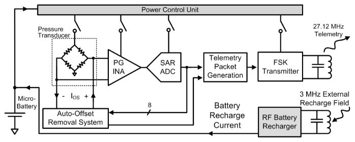
The WIMM ASIC block diagram is presented in Figure 2. The ASIC circuitry includes pressure sensing and telemetry circuits, power control circuits, and RF battery recharge circuits.
Fig. 2.
The WIMM ASIC integrates instrumentation, telemetry and power management circuitry and achieves ultra-low-power consumption. An external RF receiver/recharger receives telemetry and recharges the implanted micro-battery.
The pressure sensing and telemetry circuits form the instrumentation aspect of the bladder pressure sensor. The circuitry interfaces with a MEMS piezoresistive absolute pressure transducer (SiMicro SM5102). The piezoresistive sensor type was selected over capacitive due to greater process maturity and commercial availability. The sensor is excited with an AC stimulus to avoid large static power dissipation.
A programmable-gain instrumentation amplifier (PG INA) and successive-approximation analog-to-digital converter (SAR ADC) amplify and convert the transducer output to an 8-bit binary sample. The sample is sent to an auto-offset removal processor which continuously removes pressure baseline drift to maximize the resolution of the instrumentation system. Finally, each sample is inserted into a 14-bit packet in a custom format for robust wireless communication, and the packet is transmitted using a frequency-shift-keyed (FSK) transmitter and a 3-mm diameter, 3.3-μH surface-mount, inductive antenna.
The key power-saving feature of the WIMM ASIC is the power control unit (PCU). The PCU is a suite of very low power circuits that are always running in the background but sequentially turn on and off the vital instrumentation and telemetry circuits such that power is not consumed when it is not needed. At the minimum duty cycle, the system power consumption is minimized but only 10 samples per second are transmitted. Because the components of the PCU run at 100% duty cycle, they are all ULP designs to further reduce the time-averaged power consumption of the system.
A separate section of the ASIC is devoted to RF wireless battery recharge that operates at 3 MHz to prevent interference with the 27.12-MHz FSK telemetry. The battery recharge circuits capture RF energy that is provided by an external power transmitter in a resonant LC tank circuit and converts the energy to a regulated battery recharging current. The integrated battery recharge circuitry stops charging the micro-battery when the capacity is reached, and includes voltage limiting circuitry to protect the system in case more RF energy is received than is needed.
3.2 Power Control Unit
The WIMM achieves ultra-low time-averaged power consumption due to aggressive power management. The implanted 3.6-Volt battery has a capacity of about 3 milliamp-hours (mAh), so power management is critical to the success of the WIMM implant in chronic applications. A 6-hour recharge session can wirelessly replenish 0.6 mAh of capacity and the WIMM is intended to run for at least 48 hours between charges. This requires that the time-averaged current consumption for the WIMM must be less than about 12 μA.
Achieving such a small current draw for a continuously running implantable telemetry system is not feasible, but the ASIC PCU leverages the speed ratio between bladder pressure changes and the instrumentation capability. Bladder pressure need only be sampled at a rate of 10 Hz, even though instrumentation and telemetry circuits can provide sample rates several thousand times faster.
The PCU components are shown in Figure 3(a). The PCU circuits run continuously, so their power consumption was carefully minimized through extensive use of low-power, weak-inversion and subthreshold analog design techniques. With an operating current of 4.3 μA, the PCU circuits consume about half of the time-averaged current of the entire system. Within the PCU, the power consumption is dominated by its analog bias circuitry [Oguey and Aebischer 1997] and a mixed-signal 50-kHz clock oscillator, with schematic shown in Figure 3(b). Matched 40-nA current sources alternately charge and discharge opposite plates of a capacitor to create a triangle wave. A hysteretic differential Schmitt trigger [Majerus and Garverick 2008] controls the switch pairs S1,4 and S2,3 to maintain stable oscillation. The 50-kHz system clock is derived from the switch control signals.
Fig. 3.
The PCU schematic and current usage is shown in (a). The 50-kHz clock oscillator in (b) provides the time base for the power control signal generator.
A digital power control signal generator is the heart of the PCU, as it generates the clock and power gating signals to control the operation of the ASIC. The power control signals shut off power to individual analog circuits by interrupting the bias current that normally flows through the FETs. Implementation of this method of power control is simple, but more complex schemes might be used with circuits having large amounts of capacitance, for example.
Unlike other low-duty-cycle sampling methods, the PCU does not simply gate the power to the entire instrumentation and telemetry system, but instead operates as a “sample conveyer”, successively gating the power to 16 sections of the ASIC with each sample. A timing diagram for the most salient power control signals is shown in Figure 4. Clock signals for various blocks are not shown, but are also generated by the PCU.
Fig. 4.
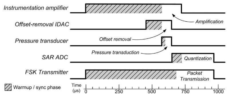
Timing diagram for some of the power control signals generated by the PCU for the acquisition and transmission of one sample. The signal timing accounts for varying warmup or synchronization periods as required by each circuit, and circuits are turned off to conserve power after they have performed their function.
The maximum duty cycle of the ASIC circuitry is the transmitter, which operates at 1% duty cycle to maintain synchronization with the external receiver. The pressure transducer operates at the lowest duty factor, 0.5%, since once its output voltage is sampled it no longer needs to be powered. When the implant is running continuously it consumes over 1 mA from the battery, but when the PCU is activated the power consumption of the transducer and instrumentation and telemetry circuits is greatly reduced, and the time-averaged current is approximately 9 μA.
3.3 Automatic Pressure Baseline Drift Cancellation
Measuring absolute pressure from within the wall of an organ is difficult because baseline pressure offset is a function of ever-changing physical and environmental factors. Atmospheric pressure can change due to ambient temperature or elevation, and physiological factors such as posture changes and tissue aging can introduce short- and long-term pressure offsets. The static pressure of the bladder is an important parameter to measure, however, so it cannot simply be ignored as in traditional AC-coupled instrumentation architectures.
The offset-cancellation circuitry of Figure 5 uses an accumulator to act like an averaging filter, and ADC samples are added to the accumulator as signed operands. Every 32 samples, the upper 8 bits of the accumulator are copied to the IDAC register, which sets the IDAC output current. Using just the upper 8 bits of the accumulator is effectively the same as dividing the accumulator value by, where 2(NA−8) is NA the accumulator length. Therefore, the value copied to the IDAC register represents a running average of the pressure samples. In steady state, the accumulator value varies with AC pressure changes, but the average value remains the same (assuming zero-mean pressure changes).
Fig. 5.
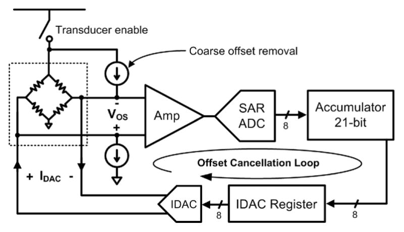
Block diagram of the WIMM auto-offset cancellation loop. The accumulator, IDAC, and coarse offset removal current sources comprise the offset cancellation loop, while the amplifier and ADC are part of the pressure sensing instrumentation.
The total offset current is generated by a pair of constant current source and a current-output digital-to-analog converter (IDAC). The constant current sources act as a coarse offset to remove the nominal transducer offset at 1-atm pressure. The IDAC performs fine offset adjustment and is bipolar to match the differential transducer. The action of the feedback loop is to calculate the value of the offset, VOS, and then subtract that amount from the pressure transducer. This feedback method yields a high-pass response (with very low frequency cut-off) for the overall system.
To prevent saturation of the analog instrumentation, offset cancellation operates continuously during the low-power 10-Hz sampling mode. The cancellation feedback loop maintains an average output of 128, or half of full-scale, at the ADC output. This maximizes the system dynamic range, providing high resolution measurements of quick pressure changes (the ADC samples) and lower resolution measurements of low-frequency pressure baseline drift (the offset IDAC values). Pressure information is not lost with this technique, since both the ADC samples and the offset values are wirelessly transmitted within the data packets.
The analog electronics have a fairly narrow dynamic range of 8 bits and a sudden step change in offset increments the accumulator at a slew rate of ±127 codes per sample. Once the pressure offset falls within the 8-bit range of the electronics, the offset-cancellation system performs linearly with an effective time constant given by Equation (1), with variables and the WIMM ASIC values listed in Table I.
Table I.
Variable Names and Design Values for Equation (1)
| Variable Name | Description | Value on WIMM ASIC |
|---|---|---|
| FS | ADC sampling frequency (Hz) | 10 |
| NA | Accumulator length (bits) | 21 |
| ND | IDAC resolution (bits) | 8 |
| RD A | Average ratio of ADC codes per IDAC code | 11 |
| (1) |
The time constant is a function of the accumulator size (NA), the IDAC resolution (ND), scaling term RD A, and the ADC sample rate. The factor RD A is a system parameter describing the IDAC LSB “weight” in ADC codes, or how many ADC codes are offset by a 1-bit change in the IDAC output. This factor is basically the loop gain of the offset cancellation system.
The values for the offset cancellation system were chosen to produce a long time constant of 75 seconds, which yields a high-pass corner frequency of about 2 mHz. This time constant was chosen to be long enough such that slow, naturally-occurring pressure changes are captured at full resolution, while preventing system saturation for inordinate time periods due to patient posture or atmospheric pressure changes.
3.4 Wireless Telemetry Protocol
The WIMM transmits pressure telemetry using a narrowband, integrated FSK transmitter [Majerus and Garverick 2008] that broadcasts on an unlicensed 27.12-MHz band. Transmission at this relatively low carrier frequency affords low power consumption due to minimal signal attenuation in tissue, and permits near-field communication at reasonable ranges using compact magnetic antennas. Bandwidth is limited, however, and the transmitter uses a 50-kbps baud rate.
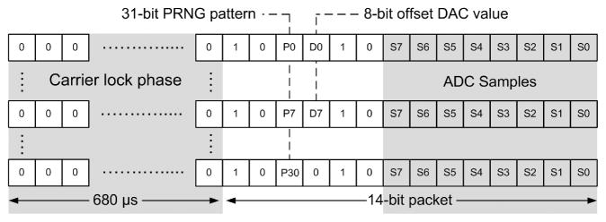
The WIMM does not require the sophisticated network protocols used by low-power intermittent transmission standards (i.e., IEEE 802.15.4/ZigBee), so a custom telemetry protocol was designed which would minimize the transmitter active time (Figure 6). The transmitter sends out 14-bit packets at a rate of 10 Hz. Each packet includes an 8-bit pressure sample plus a start frame, and a 680-μsec start-up phase is used in which the transmitter operates at frequency f0. This start-up period allows the transmitter and external receiver to synchronize before the packet is delivered.
Fig. 6.
The WIMM telemetry protocol uses a 680-μs synchronization phase, followed by a 14-bit data packet, including a start pattern. A pseudo-random bit pattern and the offset IDAC value are interleaved throughout successive packets to enable synchronization with minimal overhead.
Data packets begin with a 1–0 start pattern that is followed with two interleaved bits, corresponding to the nth bit of a pseudorandom pattern and the mth bit of the offset IDAC value. The pseudorandom pattern generator (PRNG) is implemented as a 5-bit linear-feedback shift register which yields a pattern that is 31 bits long, and the next value of the pattern, Pn, is generated for each packet [Smith and Hamilton 1966]. The offset IDAC updates once every 32 samples, so the IDAC Dm values are interleaved across multiple packets to minimize the transmitter active time. The PRNG pattern allows the receiver to determine packet order, and calculate the bit-error-rate of the wireless link. This is useful because the bladder pressure data can contain discontinuous motion artifacts which may be misinterpreted as errors, while the PRNG pattern is deterministic.
3.5 Wireless Battery Recharging
The WIMM ASIC includes circuitry to wirelessly capture and rectify RF power to produce a constant 100-μA battery recharge current. An external 15-cm, 5-μH powering coil transmits RF energy to a 7 × 17 mm, 11-μH coil within the implantable WIMM. The internal coil uses ferrite rods to shield the steel battery, and has a maximum Q of 37 at 3 MHz, which was chosen as the optimum recharge power carrier frequency, as described in Cong et al. [2009]. The external power transmission coil will be encased in a mattress to obtain an unobtrusive, consistent coupling during a recharge period while the user is resting.
Due to the small size of the internal coil, the recharge efficiency for the system is quite low, varying from 0.5 to 0.015% for implantation depths of 5 to 20 cm. Power dissipation in the external coil leads to just an 8°C rise when the coil is insulated by mattress materials, however. Even in warm ambient conditions of 30°C the recharging system would remain below the safe limit of 41°C [UL 60601-1 2003].
4. WIMM WIRELESS BENCH TESTING
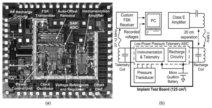
The WIMM ASIC was fabricated in the OnSemi 0.5-μm process, and Figure 7(a) shows an annotated die photograph. Wireless bench testing of the WIMM implantable device was performed using a large test board (for ease of connection) that contained the same components as the much smaller implantable WIMM (Figure 7(b)). The test board was powered by the implantable micro-battery so that it represented a fully wireless, larger version of the WIMM implantable device. The performance characteristics of the WIMM ASIC are listed in Table II.
Fig. 7.
The WIMM ASIC was fabricated in the OnSemi 0.5-μm process, and an annotated die photo is shown in (a). Wireless bench tests use a test board with the same components as the implantable WIMM, but in a larger form factor (b). A saline bath is used to simulate transmission through tissue (not shown).
Table II.
WIMM ASIC Performance Summary
| Pressure sensing range, 8-bit resolution | 200 cm H2O |
| Dynamic pressure sensing range | 2,200 cm H2O |
| Pressure resolution, > 2 mHz | 0.8 cm H2O |
| Pressure resolution, 0 – 2 mHz | 8.6 cm H2O |
| Pressure sampling rate | 10 Hz |
| Wireless telemetry center frequency | 27.12 MHz |
| Wireless battery recharge frequency | 3 MHz |
| Wireless battery recharge current | 100 μA |
| Input battery voltage | 2.7 – 3.6 V |
| Average current draw | 9 μA |
4.1 WIMM Wireless Data Transmission and Reception
Wireless telemetry from the WIMM device was tested with a 20-cm long, 0.9% saline bath between the receiver antenna and the test board (Figure 7(b)). The Class-E transmitter used for wireless recharge was operated at 3-MHz since only its 9th harmonic falls within the telemetry bandwidth and interferes only slightly with data reception. The recharge transmission coil was arranged orthogonally to the receiver antenna, representing the expected arrangement when the WIMM is implanted.
Telemetry from the WIMM was wirelessly received using a custom, external receiver that does not use regenerative stages or PLLs which require a certain amount of time to “lock in” to a carrier. A fast received-signal-strength-indicator (RSSI) circuit calculates the required receiver gain (Figure 8(a)), and a frequency discrimination de-modulator distinguishes between f0 (26.82 MHz) and f1 (27.42 MHz) to yield received binary data. Slow carrier drift is tracked by the receiver, which uses a programmable local oscillator to maintain an intermediate frequency of 10.7 MHz.
Fig. 8.
The WIMM transmits wireless telemetry in bursts, as the RSSI indicates in (a). A detailed view of the received data shown in (b), highlighting the 14-bit packet format. The receiver analyzes the packets and indicates the start of the 8-bit ADC sample with a synchronization pulse.
At an antenna spacing of 20 cm, the peak received telemetry power by the receiver antenna was −80 dBm, and the 27-MHz recharge harmonic was −30 dB relative to the telemetry signal. One example of reception under these difficult conditions is shown in Figure 8(b). Due to the limitations of the weak, pulsed telemetry signal, the bit-error-rate (BER) under these conditions was near 10−2. The BER improves dramatically at shorter transmission distances. Improvements to the receiver and error-correcting encoding on future ASICs will improve the BER at long transmission distances.
4.2 Low-Power Operation with Wireless Battery Recharge
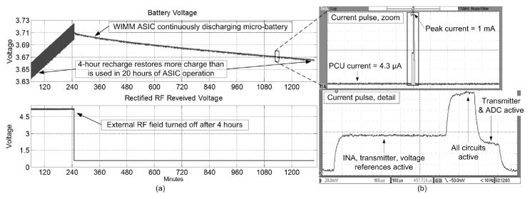
The ULP performance of the WIMM ASIC was measured by a system-level test. The battery was recharged wirelessly for 4 hours with the bench test setup shown in Figure 7(b), with 30° misalignment between the external and internal recharge coils. A 20-cm long saline bath was used to simulate the implanted environment.
The upper curve in Figure 9(a) plots the micro-battery voltage, and the lower trace shows the rectified RF voltage, as received by the WIMM recharging circuitry. Both traces are plotted against experimental time in minutes. The visible interference was due to the powerful 3-MHz recharge field which leaked into the data acquisition (DAQ) electronics. When the RF field was turned off, the rectified RF voltage decreased to about 0.7V, halting the battery recharge phase.
Fig. 9.
Wireless testing of the WIMM demonstrated that 4-hour recharge restores more charge to the battery than is used in 20 hours of operation in (a). The WIMM ASIC drew power from the micro-battery in pulses, as detailed in (b).
The WIMM ASIC operated throughout the recharge phase and continued to transmit pressure samples at a rate of 10 Hz for the rest of the 24-hour experiment. The ASIC drew current from the battery in short pulses, as shown in Figure 9(b), which plots the voltage drop across a 150-Ω resistor in series with the ASIC. The supply ripple was attenuated by bypass capacitors on the ASIC and a single large capacitor in parallel with the micro-battery. The time-averaged, 9-μA current usage of the WIMM ASIC caused the battery voltage to decrease by 50mV over 20 hours of operation. At this rate the micro-battery (with 3-mAh capacity) could power the system for over 10 days. The over-capacity of the battery implies that future versions of the WIMM can use even smaller batteries as they become available.
5. PROTOTYPE WIMM IN VIVO EXPERIMENTAL TRIALS
An implantable prototype device was fabricated and packaged for acute in vivo experimentation. The emphasis in these in vivo studies was placed on the implantation method, which required cutting the bladder wall and inserting the device beneath the mucosal layer to obtain readings of fluid pressure within the bladder. The device was not operated wirelessly, in order to eliminate these additional engineering complications.
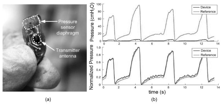
Since the implantable prototype was wired, the battery and wireless recharge coil were not included in the implantable device. The prototype implant consisted of the WIMM ASIC, pressure transducer, telemetry antenna, and two capacitors. The device measured 7.1 by 15.8 mm, and weighed 1.1 g (not including cable) after being packaged in silicone as described in Majerus et al. [2011]. The prototype transmitted telemetry wirelessly, but redundant serial data was sent over a single wire in the power/data cable. A photograph of the packaged prototype is shown in Figure 10(a).
Fig. 10.
A surgeon holds the packaged prototype in (a), and prepares to implant the device for in vivo study. Pressure recordings from the WIMM implanted within an anesthetized feline closely match those from a reference catheter in (b), after normalizing to correct for DAQ recording discrepancies.
Pressure recordings were captured in three in vivo trials with anesthetized feline and canine subjects and one ambulatory canine subject. One example recording from an anesthetized feline is shown in Figure 10(b). A DAQ system designed for microtip catheters simultaneously recorded pressure signals from a reference catheter in the bladder lumen and analog reconstructed signals from the WIMM prototype. The DAQ pressure conversion factor was calibrated for the reference, and did not match the conversion factor for the prototype device. This DAQ limitation caused the prototype (labeled “device”) signals in the upper trace of Figure 10(b) to falsely appear attenuated. After normalization to correct for the conversion factor, the WIMM signals closely matched the reference, with correlation coefficient r = 0.947 (Figure 10(b), lower trace).
The in vivo trials confirmed the ability of the WIMM system to sense bladder pressure, but indicated that a sampling rate of 10 Hz is too low for ambulatory subjects. To avoid aliasing from high-frequency motion artifacts (due to coughs, sneezes), future WIMM devices will sample at 100 Hz and use data compression techniques to maintain a low transmission rate.
6. CONCLUSION
The WIMM has been designed for wireless bladder pressure sensing in chronic, ambulatory applications. The device can be implanted within the bladder wall using minimally-invasive techniques, and fulfills the unmet need for catheter-free urodynamics and pressure feedback to neuromodulation devices for bladder control. Ultra-low-power operation is realized by the WIMM ASIC, which uses aggressive power management to consume 9 μA while providing wireless pressure telemetry at a rate of 10 Hz. The WIMM can operate for over one week from a fully-charged micro-battery, and intermittent recharge sessions can replenish the depleted charge. Future WIMM versions can use even smaller batteries as they are developed. Since in vivo applications of the WIMM will involve implantation in humans, complete wireless testing of the implanted device is required.
Acknowledgments
This work was supported by the Rehabilitation Research Service of the U.S. Department of Veterans Affairs.
ACM acknowledges that this contribution was authored or co-authored by a contractor or affiliate of the [U.S.] Government. As such, the Government retains a nonexclusive, royalty-free right to publish or reproduce this article, or to allow others to do so, for Government purposes only.
The authors would like to thank the staff and researchers of the Advanced Platform Technology (APT) Center of the Louis Stokes Cleveland Veterans Affairs Medical Center for their assistance.
Contributor Information
STEVE J. A. MAJERUS, Case Western Reserve University
STEVEN L. GARVERICK, Case Western Reserve University
MICHAEL A. SUSTER, Case Western Reserve University
PAUL C. FLETTER, Louis Stokes Cleveland VA Medical Center
MARGOT S. DAMASER, Louis Stokes Cleveland VA Medical Center
References
- Baker MW, Sarpeshkar R. Feedback analysis and design of RF power links for low-power bionic systems. IEEE Trans Biomed Circ Syst. 2007;1(1):28–38. doi: 10.1109/TBCAS.2007.893180. [DOI] [PubMed] [Google Scholar]
- Chapple CR. Primer: Questionnaires versus urodynamics in the evaluation of lower urinary tract dysfunction-one, both or none? Nature Clinical Practice Urology. 2005;2:555–564. doi: 10.1038/ncpuro0339. [DOI] [PubMed] [Google Scholar]
- Chow EY, Yang CL, Chlebowski A, Moon S, Chappel WJ, Irazoqui PP. Implantable wireless telemetry boards for in vivo transocular transmission. IEEE Trans Microwave Theory Techn. 2008;56(12):3200–3208. [Google Scholar]
- Cong P, Suster MA, Chaimanonart N, Young DJ. Wireless power recharging for implantable bladder pressure sensor. Proceedings of the 8th Annual IEEE Conference on Sensors; 2009. pp. 1670–1673. [Google Scholar]
- Cong P, Ko WH, Young DJ. Wireless batteryless implantable blood pressure monitoring microsystem for small laboratory animals. IEEE Sensors J. 2010;10(2):243–254. [Google Scholar]
- Cooper MA, Fletter PC, Zaszczurynski PJ, Damaser MS. Comparison of air-charged and water-filled urodynamic pressure measurement catheters. Neurourol Urodyn. 2011;30:329–334. doi: 10.1002/nau.20991. [DOI] [PubMed] [Google Scholar]
- Fletter PC, Majerus SJA, Cong P, Damaser MS, Ko WH, Young DJ, Garverick SL. Wireless ambulatory system for chronic bladder pressure monitoring. Proceedings of the 6th International Conference on Networked Sensing Systems (INSS09); 2009. pp. 1–4. [Google Scholar]
- Gupta A, Defreitas G, Lemack GE. The reproducibility of urodynamic findings in healthy female volunteers: Results of repeated studies in the same setting and after short-term follow-up. Neurourol Urodyn. 2004;23:311–316. doi: 10.1002/nau.20039. [DOI] [PubMed] [Google Scholar]
- Horvath EE, Yoo PB, Amundsen CL, Webster GD, Grill WM. Conditional and continuous electrical stimulation increase cystometric capacity in persons with spinal cord injury. Neurourol Urodyn. 2009;29(3):401–407. doi: 10.1002/nau.20766. [DOI] [PMC free article] [PubMed] [Google Scholar]
- Kirkham AP, Shah NC, Knight SL, Shah PJ, Craggs MD. The acute effects of continuous and conditional neuromodulation on the bladder in spinal cord injury. Spinal Cord. 2005;39(8):420–428. doi: 10.1038/sj.sc.3101177. [DOI] [PubMed] [Google Scholar]
- Majerus SJA, Garverick SL. Telemetry platform for deeply implanted biomedical sensors. Proceedings of the 5th International Conference on Networked Sensing Systems (INSS08); 2008. pp. 87–92. [Google Scholar]
- Majerus SJA, Fletter PC, Damaser MS, Garverick SL. Low-power wireless micromanometer system for acute and chronic bladder-pressure monitoring. IEEE Trans Biomed Engin. 2011;58(3):763–768. doi: 10.1109/TBME.2010.2085002. [DOI] [PMC free article] [PubMed] [Google Scholar]
- Oguey HJ, Aebischer D. CMOS current reference without resistance. IEEE J Solid-State Circ. 1997;32(7):1132–1135. [Google Scholar]
- Previnaire J, Soler J, Perrigot M, Boileau G, Delahaye H, Schumacker P, Vanvelcenaher J, Vanhee JL. Short-term effect of pudendal nerve electrical stimulation on detrusor hyper-reflexia in spinal cord injury patients: Importance of current strength. Paraplegia. 1996;34:95–99. doi: 10.1038/sc.1996.17. [DOI] [PubMed] [Google Scholar]
- Smith KD, Hamilton JC. The logical design of a digital pseudorandom noise generator. IEEE Trans Nuclear Science. 1966;13(1):371–381. [Google Scholar]
- Underwriters Laboratories. UL Safety Standard. 2003. UL 60601-1: Medical Electrical Equipment, Part 1: General Requirements for Safety. [Google Scholar]
- Wang CC, Huang CC, Liou JS, Ciou YJ, Huang IY, Li CP, Lee YC, Wu WJ. A mini-invasive long-term bladder urine pressure measurement ASIC and system. IEEE Trans Biomed Circ Syst. 2008;2(1):44–49. doi: 10.1109/TBCAS.2008.921601. [DOI] [PubMed] [Google Scholar]
- Wenzel BJ, Boggs JW, Gustafson KJ, Grill WM. Closed loop electrical control of urinary continence. J Urol. 2006;175:1559–1563. doi: 10.1016/S0022-5347(05)00657-9. [DOI] [PubMed] [Google Scholar]
- Wheeler JS, Walter JS, Zaszczurynski PJ. Bladder inhibition by penile nerve stimulation in spinal cord injury patients. J Urol. 1992;147:100–103. doi: 10.1016/s0022-5347(17)37145-8. [DOI] [PubMed] [Google Scholar]


