Abstract
Wireless control and power harvesting systems that operate injectable, cellular-scale optoelectronic components provide important demonstrated capabilities in neuromodulatory techniques such as optogenetics. Here we report a radio frequency (RF) control/harvesting device that offers dramatically reduced size, decreased weight and improved efficiency compared to previously reported technologies. Combined use of this platform with ultrathin, multijunction, high efficiency solar cells allows for hundred-fold reduction of transmitted RF power, which greatly enhances the wireless coverage. Optogenetics studies with social groups of mice demonstrate the utility of these systems, and suggest their potential for widespread use in neuroscience.
Keywords: Optogenetics, flexible optoelectronics, energy harvesting, radio frequency, photovoltaics
Introduction
Optogenetics is a neuromodulatory technique capable of exciting or inhibiting activity in specific populations of neurons rendered light sensitive through genetic modification. This method has already enabled important advances in the understanding of neural networks in the brain [1-4] and it has potential for widespread use in neuroscience research. A conventional optogenetics experiment requires insertion of an optical fiber into the brain tissue with attachment of the opposite end to a remotely located light source such as a laser or light emitting diode. Although this setup provides an ability to illuminate targeted regions of the brain, the fiber physically tethers the animal to the light source in a way that restricts movement and can lead to entanglement. Such limitations prohibit neuroscience studies involving social interactions, home cage manipulations, and/or especially for behaviors of small animals in complex environments. Alternative systems can provide useful options for large-animal research [5]. Recently reported advances in wireless, cellular-scale optoelectronics overcome these constraints through the use of ultra-miniaturized, high performance light emitting diodes (LEDs) that implant directly into the brain [6]. These systems mount on the head to harvest RF energy from a separate transmitter, multiply the voltages, and send the resulting current output to the implanted μ-ILEDs. This report summarizes technical advances that provide this type of functionality in devices that simultaneously achieve a six-fold reduction in size and a thirty-fold reduction in weight compared to previously reported systems [6]. Further, the addition of miniaturized, high performance photovoltaic cells significantly expands the operating range and reduces the required RF power.
Methods
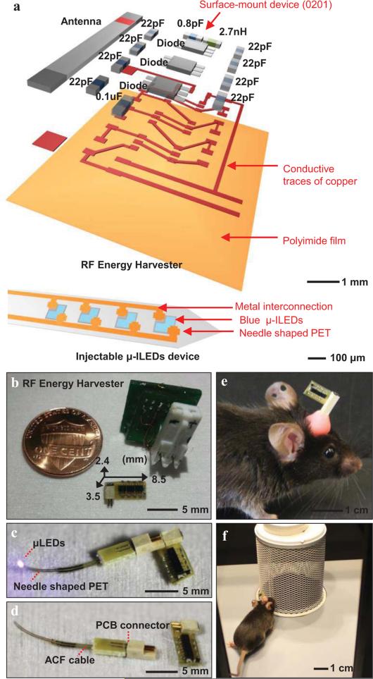
An overview of the harvester and its connection to a linear array of microscale inorganic LEDs (μ-ILEDs) on a thin, filamentary support of polyethylene terephthalate (PET) appears in Figure 1. Fabrication involves separate construction of the harvester and the injectable μ-ILEDs. For the former, photolithography and etching produced patterned traces of copper (thickness of 18 μm) on a thin polyimide substrate (thickness of 12 μm; Pyralux® AC181200R, Dupont). A solder mask defines a pattern of solder paste that consists of 96.5% tin, 3% silver, and 0.5% copper. Placing individual components for the antenna, capacitors, inductors, and Schottky diodes on these solder pads followed by baking at 250°C yields a working harvester. Overcoats of epoxy serve as encapsulation. Silver epoxy bonds the device to terminal pads on a mechanical plug receptacle. Fabrication of the μ-ILED system follows steps reported previously [6]. A matching plug (Omnetics, A79604-001) provides a releasable interface to the harvester.
Fig. 1.
Overview of a miniature, lightweight energy harvester and injectable μ-ILEDs system designed for optogenetics. (a) Exploded schematic illustration of the harvester and the μ-ILED with capacitors (0.8 pF, 22 pF, 0.1 μF), an inductor (2.7 nH), and Schottky diodes. The dimensions of the passive components in this system are specified as 0201 (0.6 mm by 0.3 mm). For the injectable device, 4 μ-ILEDs are incorporated and each has 100 μm by 100 μm dimensions. (b) Picture of a system with the design reported here, next to a US penny and a previously reported system. The miniaturized device is 2.4 mm thick, 3.5 mm wide, and 8.5 mm long; its weight is 70 mg. (c) Picture of a completed system. (d) Image of the harvester disconnected from the injectable μ-ILEDs. The μ-ILEDs mounted onto a needle-shaped substrate of PET, and interfaces to a PCB connector. (e) and (f) Photographs of a freely moving mouse with an RF harvester and injected μ-ILEDs, collected as part of optogenetic studies of social interaction.
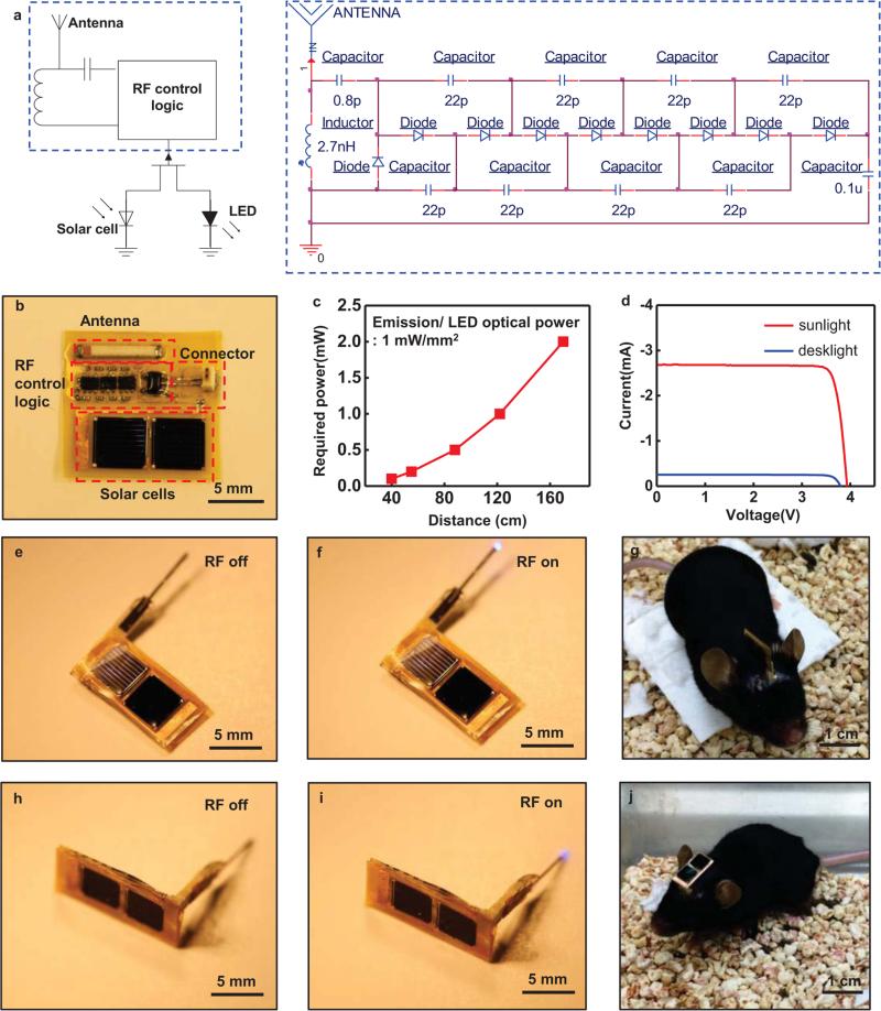
Photovoltaic enhanced systems include two multijunction solar cells connected in series. The GaAs dual junction solar cells (MicroLink Devices) have efficiencies of 25%, open-circuit voltages of 2.31 V, short-circuit currents of 11.17 mA, and fill factors of 84.6. Each cell is 32 μm thick, 5.08 mm wide, 5.08 mm long and weighs 5 mg; both connect to an RF control logic circuit via wire bonding. Fabrication of the RF component of the system follows steps as described above; the design is similar to that in Figure 1(a), but here the RF energy serves only as a trigger for enabling or disabling operation through the use of a field effect transistor as a switch. Figure 5 provides details.
Fig. 5.
Characteristics of solar powered energy harvesters that use RF energy for enabling or disabling operation. (a) Circuit diagram for solar powered harvesters, including a schematic of the RF control logic. (b) A picture of solar powered harvesters with descriptions for each functional block. (c) Transmitted power required to operate the μ-ILEDs as a function of distance. (d) Current-voltage characteristics of the photovoltaic modules (2 solar cells) under illumination with sunlight and with a desk lamp. This module provides ~ 4 V. (e), (f), (h), and (i) Images of wireless operation. (g) and (j) Images of mice with Vertical and Horizontal type solar powered harvesters, respectively.
Figure 1 shows images of an RF harvester (a,b; 2.4 mm thick, 3.5 mm wide, and 8.5 mm long), connected to an injectable μ-ILEDs system during operation (Fig. 1c), and disconnected (Fig. 1d). Injecting the polymer filament with the mounted μ-ILEDs into the brain and affixing the external components on the surface of the skull according to procedures described below yields results like those shown in the recovered, freely moving mice (Fig. 1 e, f). The weight of the entire system (~70 mg) is approximately five hundred times smaller than that of the mouse (~30 g). Compared to previously reported systems, miniaturization allows for further reductions in dimensions because reflection from the ground plane is no longer significant [7].
Adult (25–35 g) male C57BL/6J mice were group-housed, given access to food and water ad libitum and maintained on a 12 h : 12 h light : dark cycle. All animals were held in a facility in the lab 1 week prior to surgery, post-surgery and throughout the duration of the behavioral assays to minimize stress. All procedures were approved by the Animal Care and Use Committee of Washington University and conformed to US National Institutes of Health guidelines. For viral preparation, plasmid encoding pLenti-CaMKIIα-opto-β2AR-mCherry [final titer 4.8 × 10⁸ IU/ml] was obtained from the Deisseroth Laboratory at Stanford University and packaged at the WUSTL Hope Center Viral Vector Core. Lenti-PGK-GFP [viral control; final titer 1.3 × 10⁸ IU/ml] was provided by the WUSTL viral core facility [6]. For stereotaxic surgery, mice were anaesthetized (5% isoflurane) and placed in a stereotaxic frame (Kopf Instruments) where they were maintained at 1-2% isoflurane throughout the procedure [8]. Following craniotomy, mice were injected bilaterally with 1.2 μl of either lenti-EF1α-GFP or lenti-CaMKIIα-optoβ2AR-mCherry in the baso lateral amygdala (BLA) at stereotaxic coordinates from bregma: −1.3 mm (AP), ±2.9 mm (ML) and −4.9 mm (DV). For wireless μ-ILED BLA studies, animals were injected unilaterally. Mice were then implanted with μ-ILED wireless devices with coordinates adjusted from viral injection to 0.00 mm (AP), ±0.00 mm (ML), and +1.00 mm (DV). For samples mounted on releasable injection needles, the device was implanted at the desired target, artificial cerebrospinal fluid was applied to the portion of the device that remained outside of the skull to facilitate dissolution of the adhesive, and then the needle (length 5 mm, width 200 μm, thickness 10 μm) was removed after a delay of 15 min [8]. The wireless μ-ILED devices were secured using two bone screws (CMA, 743102) and affixed with Titan Bond (Horizon Dental Products) and dental cement (Lang Dental)42. Mice were allowed to recover for at least 3-6 weeks prior to behavioral testing; this interval also permitted optimal viral expression. Using tyrosine hydroxylase-Cre (TH-IRES-Cre) mice to genetically isolate LC-NA neurons, we injected Cre-dependent virus expressing channelrhodopsin-2 (AAV5-EF1α-DIO-ChR2-eYFP) into the LC and positioned a fiber optic implant at NA terminal sites in the BLA [9].
Results and discussion
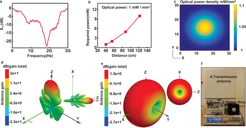
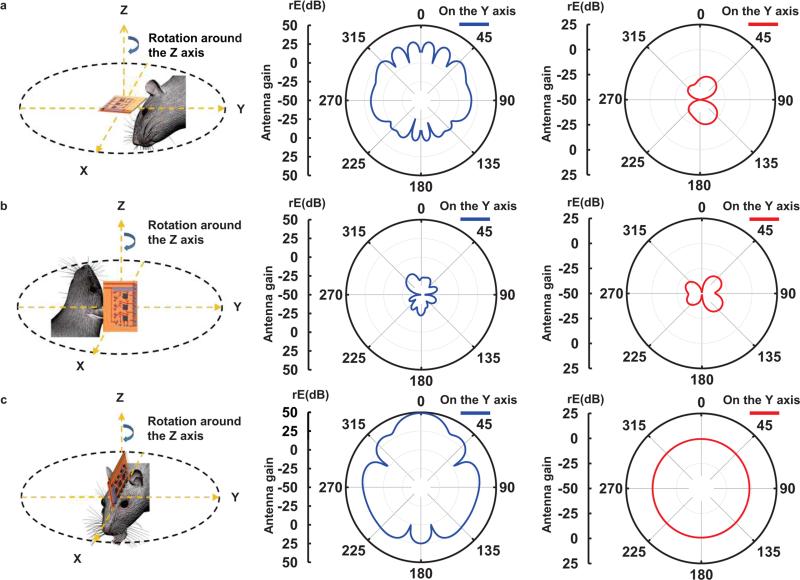
The RF harvester consists of an antenna, an impedance matching circuit, and a Villard cascade voltage multiplier (8× multiplication, to enable broad wireless coverage) [10]. This system offers broadband operation (1.6 GHz to 2.5 GHz in Fig. 2a), with potential to provide independent control of more than one type of μ-ILED. Previously reported designs offered only 4× multiplication and relatively narrow bandwidth (910 MHz to 930 MHz) with a center frequency at 920 MHz. The settling time of the current system, defined as the time for received signals to yield stabilized operation to within a specified error (10%), is fifty times shorter (2 ms) than previously achieved. Figure 2(b) presents a graph of the minimum transmitted power required to operate the μ-ILEDs as a function of separation distance. Figure 2(c) presents a computed spatial map of optical power densities across the area of a cage (30 cm by 30 cm). The results indicate variations of ~10%, which are known to have little effect on optogenetic stimulation [11]. Three dimensional (3D) plots of radiation patterns computed for a transmission antenna (19 dBi gain) and a harvester antenna appear in Figure 2(d) and (e), respectively. Radiation patterns of the transmission antenna are highly centered around the z axis due to the high gain. On the other hand, the harvester antenna has a toroidal shape, with its gain maximized on the ZX plane. The RF systems, which include a signal generator, a power amplifier, a power supply, and a transmission antenna, appear in Figure 2(f). Figure 3 shows two-dimensional plots of radiation patterns of the transmission antenna (blue) and the harvester antenna (red) for the XY, YZ and ZX planes. Here, the transmission antenna has an orientation along the Z axis. The harvester uses an electrical monopole antenna, for which case an analysis of the radiated electric field (rE) is meaningful. For the radiation plots, the Y axis represents the gain (rE) of the transmission and harvester antennas. When the harvester lies on the XY plane and the transmission antenna rotates around the Z axis, as in Figure 3(a), the harvester exhibits marginal gain. The large gain of the transmission antenna on this plane balances this effect. Coupling between the antennas is small when the harvester lies on the YZ plane and the transmission antenna rotates around the Z axis, as in Figure 3(b). When the harvester lies on the ZX plane and the transmission antenna rotates around the Z axis, as in Figure 3(c), significant power transfer occurs due to overlap in gain for both antennas. Collectively, the results in Figure 3 provide a technical basis for understanding the overall behaviors and for defining experimental conditions. These results suggest that the maximum power transfer occurs when the z direction of a harvester antenna is aligned with the Z or X direction or lies on the ZX plane of a transmission antenna.
Fig. 2.
Characteristics of the harvester the RF systems. The harvester includes an antenna, an impedance matching circuit and a Villard cascade voltage multiplier (8× multiplication, to enable broad wireless coverage). (a) Scattering parameter, S11, of the receiving antenna. (b) Transmitted power required to operate the μ-ILEDs, as a function of distance. (c) Plot of the computed spatial distribution of optical power density vertically incident across the cage (30 cm by 30 cm). 3D plots of radiation patterns of the transmission (d) and harvester (e) antennas. (f) A picture of the RF systems:1.signal generator, 2.power amplifier, 3.power supply, and 4.transmission antenna.
Fig. 3.
Radiation patterns of a transmission (blue) and harvester (red) antenna on planes (a) XY, (b) YZ, and (c) ZX. The transmission antenna has an orientation along the Z axis.
Simulations using a 3D finite element modeling tool (HFSS) reveal the maximum 1-g specific absorption rate (SAR) for the head of a human and a mouse, while harvesting a power of 2 mW. Here, a Debye relaxation model describes the biological tissues and associated dielectric constants at zero and gigahertz frequencies [12, 13]. SAR values for both cases, i.e. human (21 mW/kg) and mouse (18 mW/kg), are well below the exposure threshold level (1.6 W/kg) defined by IEEE guidelines [14].
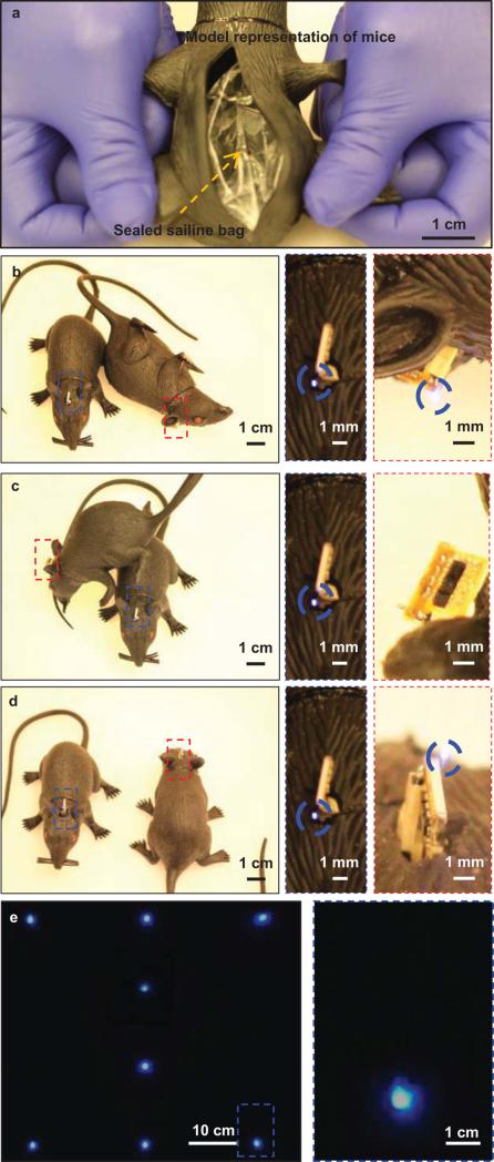
Figure 4 summarizes results of experiments that provide visual evidence of the robustness of operation in terms of position, orientation and proximity to other mice or objects. The demonstrations use model representations of mice with the μ-ILEDs exposed for ease of viewing. To approximate the radio frequency behaviors of biological tissues, each model includes an embedded, sealed bag of saline solution (80 g) as shown in Figure 4(a). Here, the transmission antenna is placed ~1 m away above the mice such that its orientation is along the Z axis. The model on the left faces toward the × direction, while the one on the right rests on its side, corresponding to the case in Figure 4(b). The enlarged view on the right indicates bright operation of the μ-ILEDs, consistent with behavior expected based on the radiation patterns in Figure 3(a). As shown in Figure 4(c), the μ-ILEDs fail to operate when one model rests directly on top of and adjacent to another, where coupling between the antennas is small as in Figure 3(b). The case in Figure 4(d) involves positioning in which, compared to Figure 4(b), the model on the right rotates (180 degrees) while the one on the left maintains its position. This setup is similar to that of Figure 3(c). The results indicate strong coupling and efficient power transfer. Simultaneous wireless operation of eight harvesters, each placed 20 cm apart, appear in Figure 4(e).
Fig. 4.
Operation of harvesters and μ-ILEDs systems demonstrated in model representations of mice. These models demonstrate function in multiple planes. (a) Picture of an embedded, sealed bag of saline (80 g) to simulate the RF properties of the body of the mouse. Here, one model lies on the ZX rotation plane as the position of the other varies from the XY rotation plane (b), to the YZ rotation plane (c), and the ZX rotation plane (d). For (b) and (d), the μ-ILEDs are operational; for (c), they are not. These findings are consistent with the radiation patterns associated with each case. (e) Image of simultaneous operation across a set of models.
Radio frequency (RF) control combined with a photovoltaic power source enables operation even in challenging scenarios, such as those described in the previous sections, and with greatly improved range and exposure levels that are far less than those needed with RF harvesting. Here, we built solar powered harvesters with different orientations (vertical and horizontal with respect to the bottom of the cage) to demonstrate two design options. Figure 5 summarizes the essential characteristics of such devices. Figure 5(a) and (b) shows a photovoltaic enhanced system in the on and off states with descriptions for each functional block. RF signals provide control, where the devices are normally in an off state. Figure 5(c) presents a plot of operating distance as a function of RF power, for comparison against similar results of Figure 2(b). Here, the optical power mentioned in Figure 5 and 6 is emission / LED optical power, not environmental optical power received by the solar cells. RF power required to switch the logic is in the range of tens of mW when the harvester operates with 5% duty cycles. Figure 5(d) presents current-voltage characteristics of the photovoltaic mini-module. The μ-ILEDs require 3V for operation; the mini-module provides ~4 V (~2 V from each of the two cells). Illumination with sunlight yields an electrical power of ~10 mW, such that four μ-ILEDs (100 μm by 100 μm) with efficiencies of 30% produce optical power of ~3 mW, corresponding to 75 mW/ mm2. Similarly, a desk lamp (output power of 20 W) placed ~20 cm away from the device yields an electrical power of ~0.3 mW and an optical output from the μ-ILEDs of 2.25 mW/mm2. As shown in Figure (e)-(j), we built solar powered harvesters with different orientations (vertical and horizontal with respect to the bottom of the cage) to demonstrate two design options. Figure 5(e) and (f) shows wireless operation of vertical type devices (V-type), and wireless operation of horizontal type devices (H-type) appears in Figure 5(h) and (i). Images of mice with V-type and H-type solar powered harvesters are shown in Figure 5(g) and (j), respectively.
Fig. 6.
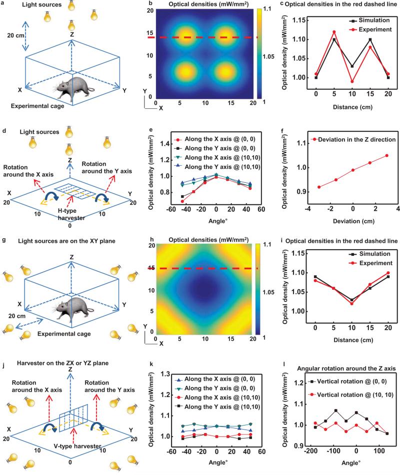
Characteristics of solar powered harvesters. (a) Illustration of an experimental cage for evaluating a harvester with H-type geometry. (b) Plot of the computed spatial distribution of optical power density vertically incident across the cage. (c) Optical power density as a function of position along the red dashed line in (b). (d) Illustration of the setup for measuring the angular dependence of illumination onto an H-type solar powered harvester located at the center and edge of the cage. (e) Plot of the measured optical power densities as a function of angular rotations around the X and Y axis at a corner and at the center of the cage. (f) Variation of an optical power density as a function of position along the Z axis at the center position of the cage. (g) Illustration of an experimental cage for evaluating a V-type device. (h) Plot of the computed spatial distribution of optical power density horizontally incident across the cage onto the left side of the V-type device, where the cells are illuminated by light sources that are placed closer to the cage. For example, the solar cells point toward the X axis when the harvester is at (10 cm, 5 cm). (i) Optical power densities as a function of position along the red dashed line in (h). (j) Illustration of the setup for measuring the angular dependence of illumination onto a V-type device located at the center and edge of the cage. Plot of measured optical power densities as a function of angular rotations around the X or Y axis (k) and the Z axis (l) at a corner and at the center.
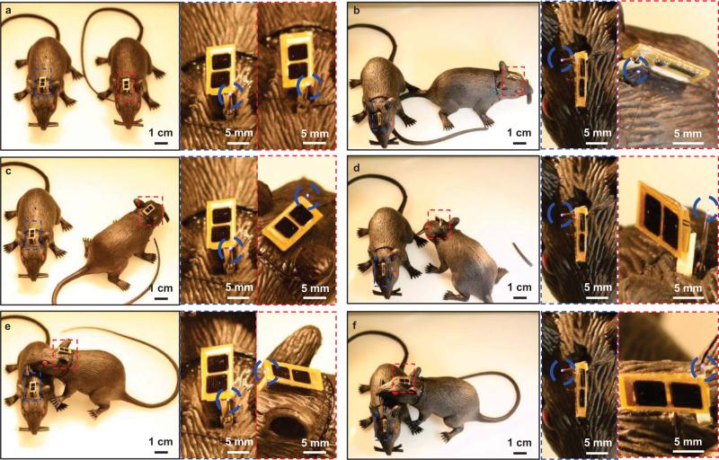
We examined various effects of illumination, alignment and angular sensitivity, and Figure 6 summarizes the results. For Horizontal type (H-type) devices, an array of four light sources provide illumination directed vertically downward (toward the XY plane) from a position 20 cm above the experimental cage (20 cm by 20 cm), as in Figure 6(a). Figure 6(b) and (c) summarize measurements and calculations that reveal the high levels of spatial uniformity in the optical power densities incident on the solar cells. The power varies, of course, with angle of rotation of the solar cells around the X or Y axes, as illustrated in Figure 6(d). Experimental measurements at a corner (0 cm, 0 cm) and at the center (10 cm, 10 cm) of the cage appear in Figure 6(e). Variations in power with position along the Z axis are small for a range of distances that corresponds to the size of typical mouse as shown in Figure 6(f). Improvements in the lighting configuration can further reduce the variations in power. A related set of measurements reveals the power that can be obtained with a set of eight light sources (illumination perpendicular to the XY plane) and Vertical type (V-type) devices. The results appear in Figure 6(g)-(l). As with the H-type case, the results indicate that excellent uniformity in power can be obtained with simple experimental setups. Model representations of mice in Figure 7 illustrate operating capabilities even in configurations similar to the case in Figure 4. Collectively, the capabilities demonstrated here clearly suggest potential for photovoltaic based optogenetics studies of multiple animals, freely moving across large areas of their environment.
Fig. 7.
(a)-(f) Operation of solar powered energy harvesters using model representations of mice ((a), (c), and (e) for H-type harvesters and (b), (d), and (f) for V-type harvesters). These models demonstrate function in situation similar to Figure 4.
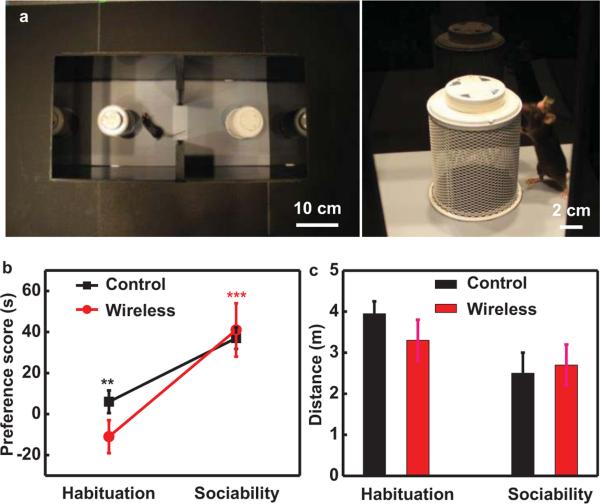
Optogenetics experiments demonstrate the ability to apply the technology in live animal models, without altering their natural behaviors. To test whether the presence of the implantable device alters behavior, we implanted one group of wild type mice and compared sociability behavior to unaltered controls. Social interaction experiments followed protocols defined by Silverman et al. with minor modifications [15]. Wireless field coverage was established prior to testing. First, we established baseline preference for the behavioral chamber (52.5 cm × 25.5 cm × 25.5 cm) for each treatment group in Figure 8(a) right (habituation). In the second phase of the cage, we placed a novel mouse randomly in one of the chambers and mice interacted with a novel social stimulus mouse placed in an inverted metal mesh pencil cup in one chamber or an empty second cup in the other chamber. Then, we recorded the time spent investigating the novel mouse (sociability). Here, sociability was calculated as 100× (novel mouse interaction time – novel object interaction time) / (novel mouse interaction time + novel object interaction time). Social stimulus mice were naïve adult male wild type C57Bl/6 mice. Cup location and social stimulus mouse order were counterbalanced. Ethovision XT software (Noldus) tracked and scored each trial. A preference is shown as an increase in time from baseline values. Both wild type and implanted mice show significantly increased time investigating the novel mouse in Figure 8(b) (**p < 0.01, ***p < 0.001 via Student's paired t-test) and hence show increased sociability [15], thus demonstrating the implant does not affect social interaction. Both wild type and implanted groups also showed no difference in distance traveled during each phase of the behavioral trial in Figure 8(c) demonstrating that the implant does not alter locomotor behavior. Taken together these data illustrated that the implant does not alter social or locomotor behavior compared to wild type controls. Detailed biological studies with these devices show expected optogenetically induced responses [9].
Fig. 8.
(a) Layout of social interaction behavioral cage. (b) Mice implanted with wireless devices (red; n=7) show increased preference for novel mouse familiar to mice without wireless implants (black; n=9). (c) Mice with wireless implants show no significant differences in locomotor behavior compared to mice without implants. Data are mean +/− SEM.
Conclusion
The results presented here demonstrate that miniaturized RF harvesters, and RF control strategies with photovoltaic harvesters can, when combined with injectable μ-ILEDs, offer versatile capabilities in optogenetics. Experimental and modeling studies establish a range of effective operating conditions for these two approaches.
Acknowledgement
This work is supported by the NIH Common Fund; National Institute of Neurological Disorders and Stroke, NIH, R01NS081707 (to JAR, MRB). This work was also supported by NIH, NIDA, EUREKA, R01DA037152 (to MRB), and F31MH101956 (to JGM), the W.M. Keck Fellowship (MJS). Finally, we thank the Gereau laboratory (WUSTL).
References
- 1.Boyden ES, Zhang F, Bamberg E, Nagel G, Deisseroth K. Millisecond-timescale, genetically targeted optical control of neural activity. Nat Neurosci. 2005;8:1263–1268. doi: 10.1038/nn1525. [DOI] [PubMed] [Google Scholar]
- 2.Adamantidis AR, Zhang F, Aravanis AM, Deisseroth K. Neural substrates of awakening probed with optogenetic control of hypocretin neurons. Nature. 2007;450:420–424. doi: 10.1038/nature06310. [DOI] [PMC free article] [PubMed] [Google Scholar]
- 3.Berndt A, Lee S, Ramakrishnan C, Deisseroth K. Structure-guided transformation of a channelrhodopsin into a light-activated chloride channel. Science. 2014;344:420–424. doi: 10.1126/science.1252367. [DOI] [PMC free article] [PubMed] [Google Scholar]
- 4.Diesseroth K. Circuit dynamics of adaptive and maladaptive behavior. Nature. 2014;505:309–317. doi: 10.1038/nature12982. [DOI] [PMC free article] [PubMed] [Google Scholar]
- 5.Paralikar K, Cong P, Yizhar O, Fenno LE, Santa W, Nielsen C, Dinsmoor D, Hocken B, Munns GO, Giftakis J, Deisseroth K, Denison T. An Implantable Optical Stimulation Delivery System for Actuating an Excitable Biosubstrate. IEEE JSSC. 2011;46:321–332. [Google Scholar]
- 6.Kim T, McCall JG, Jung YH, Huang X, Siuda ER, Li Y, Song J, Song YM, Pao HA, Kim R, Lu C, Lee SD, Song I, Shin G, l-Hasani R, Kim S, Tan MP, Huang Y, Omenetto FG, Rogers JA. Injectable, Cellular-Scale Optogenetics with Applications for Wireless Optogenetics. Science. 2013;340:211–216. doi: 10.1126/science.1232437. [DOI] [PMC free article] [PubMed] [Google Scholar]
- 7.Balanis CA. Antenna theory analysis and design. 3rd ed. Wiley-Interscience; New York: 2005. [Google Scholar]
- 8.McCall JG, Kim T, Shin G, Huang X, Jung YH, Al-Hasani R, Omenetto FG, Bruchas MR, Rogers JA. Fabrication and application of flexible, multimodal light-emitting devices for wireless optogenetics. Nat Protoc. 2013;8:2413–2428. doi: 10.1038/nprot.2013.158. [DOI] [PMC free article] [PubMed] [Google Scholar]
- 9.Ed S, McCall JG, Al-Hasani R, Shin G, Park S, McElligott ZA, Schmidt MJ, Anderson SL, Planer WJ, STuber GD, Rogers JA, Bruchas MR. Optodynamic simulation of β-adrenergic receptor signaling. submitted to Nature Comm. doi: 10.1038/ncomms9480. [DOI] [PMC free article] [PubMed] [Google Scholar]
- 10.Lee T. The Design of CMOS Radio-Frequency Integrated Circuits. 2nd ed. Cambridge, New York: 2004. [Google Scholar]
- 11.Mattis J, Tye KM, Ferenczi EA, Ramakrishnan C, O'Shea DJ, Prakash R, Gunaydin LA, Hyun M, Fenno LE, Gradinaru V, Yizhar O, Deisseroth K. Principles for applying optogenetics tools derived from direct comparative analysis of microbial opsins. Nature Methods. 2012;9:159–172. doi: 10.1038/nmeth.1808. [DOI] [PMC free article] [PubMed] [Google Scholar]
- 12.Gabriel S, Lau RW, Gabriel C. Changes in the dielectric properties of rat tissue as a function of age at microwave frequencies. Phys. Med. Biol. 2001;46:1617–1629. doi: 10.1088/0031-9155/46/6/303. [DOI] [PubMed] [Google Scholar]
- 13.Park S. Enhancement of Wireless Power Transmission Into Biological Tissues Using a High Surface Impedance Ground Plane. Progress In Electromagnetics Research. 2013;135:123–136. [Google Scholar]
- 14.Institute of Electrical and Electronic Engineers . IEEE Standard C95.1. IEEE; New York: 2005. IEEE Standard for Safety Levels with Respect to Human Exposure to Radio Frequency Electromagnetics Fields, 3 kHz to 300 GHz. [Google Scholar]
- 15.Silverman JL, Yang M, Lord C, Crawley JN. Behavioural phenotyping assays for mouse models of autism. Nat Rev. Neurosci. 2010;11:490–502. doi: 10.1038/nrn2851. [DOI] [PMC free article] [PubMed] [Google Scholar]


