Abstract
Superparamagnetic micro-bead chains and microswimmers under the influence of an oscillating magnetic field are studied experimentally and numerically. The numerical scheme composed of the lattice Boltzmann method, immersed boundary method, and discrete particle method based on the simplified Stokesian dynamics is applied to thoroughly understand the interaction between the micro-bead chain (or swimmer), the oscillating magnetic field, and the hydrodynamics drag. The systematic experiments and simulations demonstrated the behaviors of the microchains and microswimmers as well as the propulsive efficiencies of the swimmers. The effects of key parameters, such as field strengths, frequency, and the lengths of swimmer, are thoroughly analyzed. The numerical results are compared with the experiments and show good qualitative agreements. Our results proposed an efficient method to predict the motions of the reversible magnetic microdevices which may have extremely valuable applications in biotechnology.
I. INTRODUCTION
Magnetorheological (MR) suspension is an artificial and smart fluid comprising superparamagnetic solid particles suspended in a nonmagnetic solvent. Because of the superparamagnetism of these microbeads, they can be manipulated by an applied external magnetic field and have been popularly used in microfluidics to design micro devices, such as micromechanical sensors,1,2 micromixers3–5 and artificial swimmers,6–8 as well as micro-total-analytical-systems devices, which are tools for biological and biochemical analyses.9 The distinct behaviors of such magnetic particles are observed under various field configurations, and such different patterns are important issues to their application. Kang et al.4 suggested the periodic breaking and reformation behavior of the rotating chain as the most efficient way to induce mixing of fluids at the micro scale. However, ruptures in the oscillating chains severely decrease the swimming efficiency of micro-swimmers.8 To effectively employ an dynamical magnetic micro-bead chain to their potential applications, detailed understandings of the dynamics and behaviors are essential. Therefore, both the computational and experimental investigations into the dynamics of the magnetic microspheres have drawn much attention in recent years. Experimental studies conducted by Melle et al.10–13 investigate the dynamics of multiple-interacting particle chain structures. The dimensionless Mason number (Mn) defined as the ratio of induced drag to dipolar attraction is employed to describe the various dynamical behaviors of the rotating microchains. The dynamics of the numerical results demonstrated by Melle et al.11–13show good agreement with their previous experiments, even thought the effect of hydrodynamic interaction between the particles is ignored in their scheme. Gao et al.14 focus on the controlled rotational dynamics of a single magnetic particle chain in an infinite fluid domain through experimental and numerical studies. In addition, a novel dimensionless parameter (Rt) is derived as the control parameter to define the dynamics of the rotational bead chain. Yadav et al.15 and Krishnamurthy et al.16 suggested that the particle dynamics method can accurately predict the microbead chain dynamics.
As to the investigations into the dynamics of the oscillating chains, Li et al.7,17–19 performed systemic experiments to define the distinct behaviors of the microchain subjected to an external field composed of a static directional field and dynamical perpendicular component. Their experimental results suggested that the criterion of structural stability of the oscillating chain can be effectively determined by the value of (N × Mn1/2), which was confirmed by Lin et al.20 via various experiment conditions with stronger viscous solvent and various diameters of magnetic microbeads. Moreover, the mechanisms concerning the structural instability of an oscillating micro-bead chain are also addressed based on systematic experiments.20 Compared with the rotating chain, less attention has been drawn to the numerical and experimental comparisons of such an oscillating chain. Although there is much previous experimental work on dynamics of suspended magnetic particles subjected to an oscillating field, the behaviors of the chain are not predicted accurately, because the stability criterions were derived from the experimental results. Motivated by these works, we numerically and experimentally study the motions of magnetic chains formed by superparamagnetic particles as active microswimmers. In the present work, 3D simulations are conducted to investigate the dynamical mechanism of the magnetic microchain and magnetic microswimmer by using a hybrid method of the lattice Boltzmann method,21 immersed boundary method22 and discrete particle method based on the simplified Stokesian dynamics. The numerical results compared with the experiments show good qualitative agreements and propose an efficient method to predict the motions of the reverse microdevices which may have extremely valuable applications in medicine, biology, and material science.
II. NUMERICAL METHODS
The behaviors of a magnetic chain and swimmer are dominated by the competition between magnetic forces and induced hydrodynamic drags. Therefore, both the particle-particle interaction and the particle-fluid have to be considered in the simulations. In order to simulate the dynamical behaviors of magnetic chain and swimmer, a hybrid numerical scheme, which consists of lattice Boltzmann method, immersed boundary method, and discrete particle method, is implemented in the present study. The fluid flow is solved numerically by the lattice Boltzmann method. To deal with solid particles, immersed boundary method is adapted. Finally, the discrete particle method is used to describe the motion of these solid particles.
Lattice Boltzmann method is employed to simulate fluid flows in this study. A feature of lattice Boltzmann different from other numerical methods is that the velocity space of the fluid particles is also discretized. This means particles can only move in certain finite number of directions. The directions the particle allowed to move depend on the chosen lattice discretization scheme. Thus, lattice Boltzmann equation at position x and time step t is described as
| (1) |
where distribution function fi represents the motion of the virtual particle for each velocity direction at each lattice point, ci is the lattice speed in direction i, τ denotes the relaxation time determined from velocity of virtual particle and kinematic viscosity, and is the local distribution function, which is obtained from Maxwell-Boltzmann equilibrium distribution.23 The lattice Boltzmann method associated with 3D15V model24 is used to solve the fluid flow. Implementation of this lattice Boltzmann method is quite standard in common studies of computational fluid dynamics, so that the readers are referred to Ref. 21 for more details.
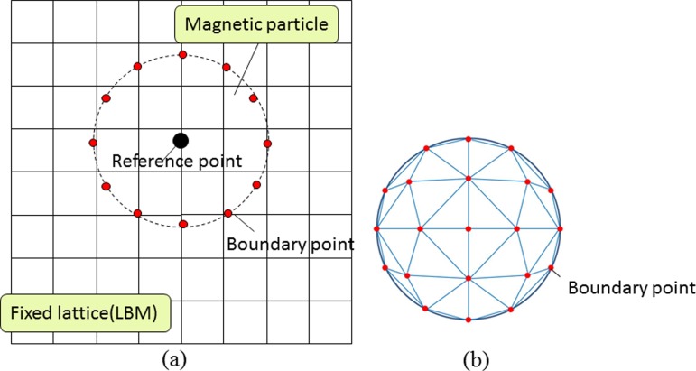
Magnetic beads are regarded as spherical solid objects in this present work. In order to model spherical objects in flow calculation with lattice Boltzmann method, immersed boundary method developed by Peskin22 is implemented to simulate particle dynamics. The particles are treated as elastic deformable objects with high stiffness in this method. Fig. 2 shows an example for explanation of immersed boundary method. As shown in Fig. 1(a), a particle is discretized into small segments with boundary points, which can be slightly distorted from its original position due to the influences of surrounding flow. The distortion of boundary points is resulted from the restoring forces of Hook's law acting on the particle. These forces can be calculated as interaction force between particles and fluids.
FIG. 2.
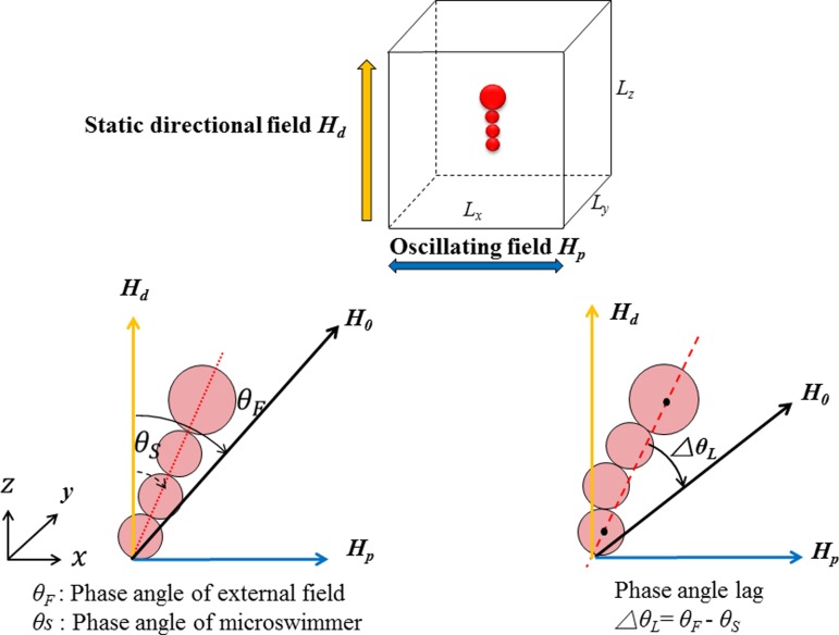
Analytical model for magnetic microswimmer. Lx:Ly:Lz = 100:50:100 and every lattice spacing is one. The magnetic swimmer (chain) oscillates along the external field but lags behind by phase lag angles (denoted as △θL). The phase lag (△θL) is defined by the angle between the centerline of the swimmer and the orientation of the overall field. For a deformed swimmer, the centerline is replaced by the straight line between the centers of the mass of the first particle (head) and last particle (tail), as shown in the figure on bottom right.
FIG. 1.
Example of 2D and 3D arrangements of boundary points on the surface of the spherical particle by using immersed boundary method.
In the present study, the structure of triangle segments shown in Fig. 1(b) is used to represent spherical magnetic particle. The number of boundary points for a single magnetic particle is Nb = 402. For easy understanding, the spherical particle shown in Fig. 1(b) is only divided into 6 pieces by 5 plains in horizontal directions, which creates 21 boundary points on each side. We use the 402 boundary points on the spherical surface arranged in the same way, when the spherical particle is divided into 20 pieces by 19 plains in horizontal direction. Influences of surrounding fluids on magnetic particles are calculated from discrepant velocity between particle and flow around each boundary point. Interaction force obtained by this immersed boundary method is treated as an external force and can be applied to flow simulation by the lattice Boltzmann equation expressed in Eq. (1).
In order to completely describe the motion of the magnetic particles, the discrete particle method is implemented. The translational and rotational equations of particle motion are expressed as
| (2) |
| (3) |
where N is the total number of particle, MN and UN, respectively, denote the mass and translational velocity, n is the boundary point number, Nb is the total number of boundary points, k is the stiffness, is the deformation of boundary point, and stand for the force and torque, respectively, and are the force and torque of magnetic dipole-dipole interactions, respectively, and IN is the moment of inertia. Angular velocity and magnetic torque are represented by ωN and , respectively. Simulations performed in uniform magnetic field are applied at each time step. Therefore, both the magnetic force and torque caused by magnetic dipole-dipole interaction are considered. On the other hand, only torque is generated by magnetic field. The magnetic dipole-dipole interaction force acting between particles i and j is described as
| (4) |
Here, μ0 = 4π × 10−7 N/A2 is the magnetic permeability of free space, also named as vacuum permeability; mi, and mj are strength of magnetic dipole moment for ith and jth particle, respectively; and rij is distance between particle i and j. Magnetic dipole moment of a spherical particle in a fluid is given by
| (5) |
where di is particle diameter, H0 is applied magnetic field vector, and μf and μp are permeability of fluid and magnetic particle, respectively. We assume μf = μ0 = 4π × 10−7 N/A2, μp = 100μ0. The magnetic dipole-dipole interaction torque and magnetic field torque are described in the following equations:
| (6) |
| (7) |
III. NUMERICAL CONDITIONS
Fig. 2 illustrates the 3D analytical model for simulating the behaviors of magnetic microchain and magnetic microswimmer. As depicted in the figure, the models of chains consisting of particles with different sizes are constructed to simulate moving swimmers. The numbers of lattices on the x, y, and z axes (denoted as Lx, Ly, and Lz, respectively) are 100, 50, and 100, respectively. For simulating the chain comprising 9 particles (denoted as P9 chain), the numerical region of Lx:Ly:Lz = 100:50:100 is adopted. As to the simulation for a longer chain composed of 15 particles, we use Lx:Ly:Lz = 150:50:150 lattices as the basic numerical region. A periodic boundary condition is imposed in all directions. Moreover, the larger particle with diameter of 4.5 μm is corresponding to 8 lattices in numerical model, while the smaller diameter of 2.8 μm is 5 lattices. To investigate effects of controlling parameters on the behavior of particles, various strengths of field Hd and Hp as well as the frequency of an oscillating magnetic field f are applied. Total time step is 4 × 10⁵ and the frequency f = 2Hz corresponds to 2 × 10⁵ time steps. During the simulations, we assume the static directional magnetic field Hd aligning in the z direction and sinusoidal oscillating magnetic field Hp is parallel to the x direction. Note that the representative images of numerical results are all shifted 90° clockwise in Section V to compare with the experimental snapshot and analyze the motions of the chains and swimmers conveniently.
IV. EXPERIMENTAL PROCEDURE
The experimental method in this present work is mostly the same as what was addressed by Li et al.7,8 Micro-sized magnetic particles are initially dispersed in distilled water. Superparamagnetic particles composed of iron oxide grains (Fe3O4) embedded in polystyrene microspheres were used to create linear chains and microswimmers. To observe and manipulate the particles simply and conveniently, microbeads with diameters d = 4.5 μm and 2.8 μm and susceptibility χ = 1.6 and 1.0, respectively, were used. The superparamagnetic property of these particles reveals that they are magnetized under an external field and completely demagnetized when the field is removed, thus enabling the creation of various reverse micro-devices.
To create the microchain and microswimmer, two magnetic fields were employed. The chain or swimmer was first aligned with a homogeneous static field Hd, generated by a pair of coils powered by DC power sources. Then, a dynamical sinusoidal field Hv with a maximum amplitude Hp and an adjustable frequency of f, that is, Hv = Hp sin(2πft), were applied in a direction perpendicular to Hd. These two fields have comparable amplitudes, resulting in an overall oscillating field H0 = Hdi + Hvj, where i and j are unit vectors in the directional and perpendicular axis, respectively. Under this field configuration, the phase angle trajectory of the external field is expressed as θF(t) = tan−1[(Hp/Hd)sin(2πft)] associated with an amplitude of θAmax = tan−1(Hp/Hd). Note that the orientations of the Hd and Hp in experimental scenario are shifted 90° clockwise from the axes depicted in the simulation model.
It is well understood that the behavior of a magnetic chain is dominated by the competition between magnetic forces and induced hydrodynamic drags, which is defined as a dimensionless Mason number (Mn). When a chain comprising N particles is subjected to an external field, it experiences a magnetic torque (Mm) and an opposing viscous torque (Mv) is expressed as5,25
| (8) |
| (9) |
| (10) |
Here, μ0 and μr are the vacuum permeability and relative permeability of the solvent, respectively; is the dipole moment of a magnetic particle; a is the radius; △θL is the instantaneous phase angle lag between the field and the chain; and η and ω are the solvent fluid viscosity and angular speed of the chain, respectively.
V. RESULTS AND DISCUSSION
A. Simulations for motions of magnetic microchain
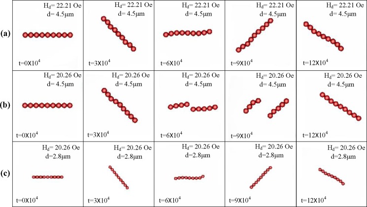
The early experimental literatures7,17 reveal the micro-chains under a dynamical magnetic field may behave from rigid body motion, bending distortions, and rupture failures. It is believed that these distinct behaviors may be affected by the key controlling parameters such as the number (N) and diameter (d) of the beads in the chain and the directional field strength (Hd). In general, a stronger directional field strength is favorable for stabilizing the structure of the chain, while the perpendicular field tends to destabilize the chaining structure. In addition, the interactions between the two components results in the maximum oscillating amplitude and local instantaneous angular velocities. The dynamical behaviors of an oscillating chain comprising 9 particles (P9 chain) with different diameters subjected to different directional magnetic field strengths are simulated and shown in Fig. 3. As depicted in Fig. 3(a), the P9 chain in a stronger directional field strength of Hd = 22.21 Oe oscillates stably and rigidly with the field. Nevertheless, if the directional magnetic field is weakened to Hd = 20.26 Oe, a single breakage of the chain occurs at t = 6 × 10⁴ as shown in Fig. 3(b), due to the greater instantaneous angular velocity and induced drag. On the other hand, if a chain composed of smaller beads than those shown in Figs. 3(a) and 3(b) is subjected to identical weaker field strength of Hd = 20.26 Oe, the microbead chain starts oscillating in a stable structure as shown in Fig. 3(c). The overall patterns of oscillation appear great similarities with the chain consisting of larger beads shown in Fig. 3(a). This result indicates that the motions of magnetic microchain are dominated by both the magnetic interaction force between particles and the viscous force acting on the dynamical particles in the fluid. The calculations for the interaction forces using the numerical method enable us to consider both hydrodynamic and magnetic interactions in a fully coupled manner.
FIG. 3.
Dynamic behaviors of an oscillating chain consisting of 9 beads (P9 chain) with a field strength of Hp = 25.08 Oe, frequency f = 2 Hz, and directional field strength of (a) Hd = 22.21 Oe and (b) Hd = 20.26 Oe for beads with diameter of 4.5 μm and (c) Hd = 22.21 Oe for smaller particles with diameter of 2.8 μm.
Fig. 4 demonstrates the pressure distribution around the P9 oscillating chain shown in Fig. 3(b) near the time of rupture, i.e., t = 5.0 × 10⁴, 5.5 × 10⁴, and 6.0 × 10⁴. The microchain oscillates in a counterclockwise direction and rupture at middle of the chain at t = 6.0 × 10⁴. Apparently, the outer part of the chain experiences higher pressure than the central section, and the lower pressure area is observed at the opposite side. The particles near the outer part of the chain move at a faster velocity than the central ones resulting in such pressure distribution. Consequently, the strong shear force acting on the chain due to the gradient of the pressure appears and leads to the rupture.
FIG. 4.
Pressure distribution of a P9 chain comprising beads with diameter of 4.5 μm subjected to a field configuration of Hd = 20.26 Oe, Hp = 25.08 Oe, and f = 2 Hz. The strong shear force acting on the chain perpendicular to the direction of the magnetic attraction force leads to the instability of the structure of the chain.
B. Qualitative comparisons between the motions of the experimental and numerical chains
In this study, qualitative comparisons are carried out between experimental and 3D numerical dynamic results of magnetic microchains subjected to an oscillating field. In Fig. 5, the experimental [Figs. 5(a) and 5(b)] and numerical [Figs. 5(c) and 5(d)] results are depicted for the chains composed of 15 and 14 beads with diameters of 4.5 μm, respectively. In the experimental case (a), rupture of the chain occurs near the center under weaker directional and dynamical perpendicular field strength of Hd = 18.15 Oe and Hp = 18.73 Oe, respectively. These nearly ideal experiment results demonstrate the magnetic particles which have identical magnetic and dimensional properties without any external interference result in a static center single particle, while forces acting on both of its sides are opposite and equal. The nearly identical pattern simulated from the numerical method is shown in Fig. 5(c), in which the oscillating chain is in the presence of field strength of Hd = 22.21 Oe and Hp = 25.08 Oe. Nevertheless, such phenomenon is not stable; Gao et al.14 demonstrated a similar pattern for microchains subjected to a rotating field and reported that the microbeads are neither perfectly monodispersed nor do they have identical magnetic susceptibilities to lead to such a state of particle dynamics. In addition, the particle surface interactions along with environmental disturbances such as the nonhomogeneity of the applied magnetic field must be considered. Therefore, after one or two cycles of rupture and reformation, the symmetry of the rupture disappears and the chain quickly shifts to the behavior as depicted in Figs. 5(b) and 5(d), which reveal the more unstable modes of dual breakups under the influence of the stronger field strength. It can be understood that the amplitude of an oscillating chain is dependent on the maximum phase angle trajectory of the external field expressed as θAmax = tan−1(Hp/Hd). We can expect that the amplitude and the structural deformation of the oscillating chain may become more significant as the ratio of perpendicular field strength (Hp) to directional field strength (Hd) increases. As shown in the experimental case of Fig. 5(b), even the increasing directional field strength is favorable for the structural stability of the chain, when the strength of the dynamical field exceeds a critical value, which is 18.73 Oe < Hp < 25.70 Oe for this case, the more unstable patterns of dual breakages are observed, i.e., the chain begins to breakup into three separated segments instead of a single breakage near the center of the chain. The detailed experimental discussion of the different patterns of rupture instability were presented by Lin et al.20 On the other hand, a similar dual breakages pattern of numerical results is shown in Fig. 5(d). When both the static and dynamical field strengths increase to Hd = 30 Oe and Hp = 48.02 Oe from the weaker strength Hd = 22.21 Oe and Hp = 25.08 Oe, a more prominent oscillation with a larger amplitude is observed. Due to the larger oscillating amplitude within a constant period, the instantaneous angular velocity and induced drag are also greater. Consequently, instead of a single breakage near the middle of the chain as shown in Fig. 3, the P15 longer chain begins to rupture into three segments at t = 6 × 10⁴ due to the stronger induced drag when the field exceeds a certain critical strength. The simulated oscillating dynamics of a magnetic particle chain show great similarities with those observed from the video-microscopy experiments shown in Fig. 5(b). Therefore, the numerical results obtained from the hybrid lattice Boltzmann method may qualitatively describe the dynamics of an oscillating magnetic bead chain, which has potential applicability in a laboratory-on-chip system.
FIG. 5.
Dynamic behaviors of ruptured oscillating magnetic microchain. Experiments: [(a) and (b)] and simulations: [(c) and (d)]. In the experimental case, the microchain composed of 14 particles (P14) subjected to a weaker field strength of (a) Hd = 18.15 Oe and Hp = 18.73, and stronger conditions (b) Hd = 24.15 Oe and Hp = 25.70 Oe, with an identical frequency f = 1Hz. The numerical P15 chain is subjected to fields of (c) Hd = 22.21 Oe and Hp = 25.08 Oe, and (d) Hd = 30.00 Oe and Hp = 48.02 Oe with f = 2 Hz.
C. Qualitative comparison of stability criterion
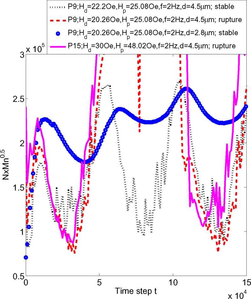
The early reports reveal that the rupture patterns of the magnetic chains are important to their application. Kang et al.4 and Gao et al.14 proposed that the fracture and reformation of rotating chains may lead to more efficient mixings. However, rupture in the oscillating chains significantly compromises the swimming efficiency of micro-swimmers.8 In the worst case, the swimmer may permanently rupture and fail to carry out its mission. This indicates avoiding the structural instability of the chain is an important issue. Li et al.17 proposed the criterion value of N × Mn1/2 for chaining instability through systemic experiments, where N and Mn are shown in Eqs. (8)–(10), and represent the number of particle and dimensionless Mason number, respectively. In this study, the numerical method is implemented to predict the instability of the chain by calculating the N × Mn1/2. The values of N × Mn1/2 before ruptures in their corresponding critical field conditions are depicted in Fig. 6. The rupture instabilities all occur at the moment when N × Mn1/2 = 2.6 × 10⁵–3 × 10⁵ near t = 6 × 10⁴, corresponding with the rupture cases as shown in Figs. 3 and 5. Qualitatively, the numerical stability criterion shows a similar trend to the experimental results, which can be used to predict the structural instability of the oscillating chains or swimmers.
FIG. 6.
Evolutions of the numerical values of N×Mn1/2 for the cases demonstrated in Figs. 3 and 5 within 1.5 × 10⁵ time steps. The chains are ruptured if the manipulating conditions exceed the stable criterion value of N ×Mn1/2 = 2.6 × 10⁵–3 × 10⁵.
D. Motions of magnetic microswimmer
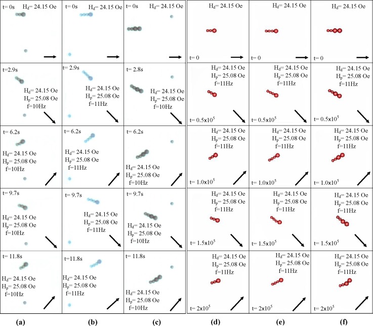
The motions of the experimental [Figs. 7(a)–7(c)] and numerical [Figs. 7(d)–7(f)] microswimmers with different configurations are demonstrated in Fig. 7. All swimmers are first formed by applying a static directional field strength of Hd = 24.15 Oe, then a dynamical oscillating field strength of Hp = 25.08 Oe with increasing frequency is applied to generate propulsion for swimming. As shown in Fig. 7, all swimmers start accelerating at t > 2.9 s or time step = 0.5 × 10⁵, when the oscillating frequencies are raised to 10–11 Hz. As a result, swimmers apparently move toward the directions of their centers of mass (larger particles), i.e., they move right in Fig. 7.
FIG. 7.
Images of three types of microswimmers under field strengths of Hd = 24.15 Oe and Hp = 25.08 Oe with a frequency of f = 10–11 Hz. The S2L1 (stands for the swimmer consisting of 2 small and 1 large particles), S3L1, and S2L2 shown in (a), (b), and (c) are obtained from video-microscopy experiments, whereas (d), (e), and (f) demonstrate the numerical patterns of the three swimmers. The black arrows inside images represent the strength and orientation of the overall field.
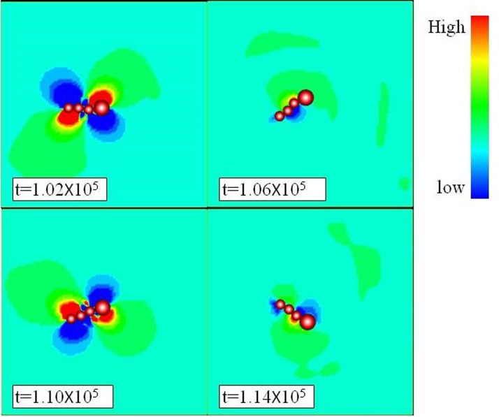
To investigate the forces distribution of the oscillating swimmer, dynamics simulations are performed. Fig. 8 illustrates the pressure distribution around the S3L1 microswimmer shown in Fig. 7(e). A strong gradient of pressure is observed when the structure of the swimmer experiences an accelerated process (t > 1.02 × 10⁵and t > 1.1 × 10⁵), in which the hydrodynamic drag acting on the swimmer increases. Moreover, at the paddling time steps of the microswimmer, the pressure distribution around the large particle differs from the counterpart near the tail of the microswimmer. Such asymmetric distribution comes from the different diameters of particles and the shifting mass of center of the microswimmer. Consequently, the asymmetry of particles motion and flow pattern is essential to generate propulsive force which drives the magnetic microswimmer to move forward.
FIG. 8.
Pressure distribution of the micro swimmer consisting of three small and one large particles (denoted as S3L1) under field strengths of Hd = 25.08 Oe, Hd = 24.15 Oe, and frequency is 11 Hz. The swimmer oscillates counterclockwise at time step t = 1.02 × 10⁵ and starts oscillating clockwise between t = 1.06 × 10⁵ and 1.14 × 10⁵.
E. Effects of controlling parameters on propulsive efficiency of microswimmer
The effect of various controlling parameters, such as the oscillation frequency, numbers, and diameters of the beads in the swimmer and the field strength, are investigated to obtain more insights into manipulating the swimmer by the numerical method. To investigate the propulsive efficiency for swimmers under various controlling parameters, the dimensionless Strouhal number (St) defined as St = fA/U is applied, where U and A represent the forward velocity and the oscillating amplitude of the swimmer, respectively, and f is the oscillating frequency.
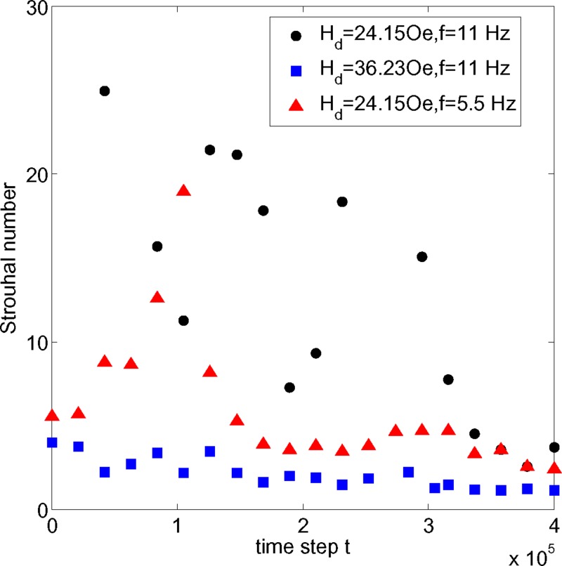
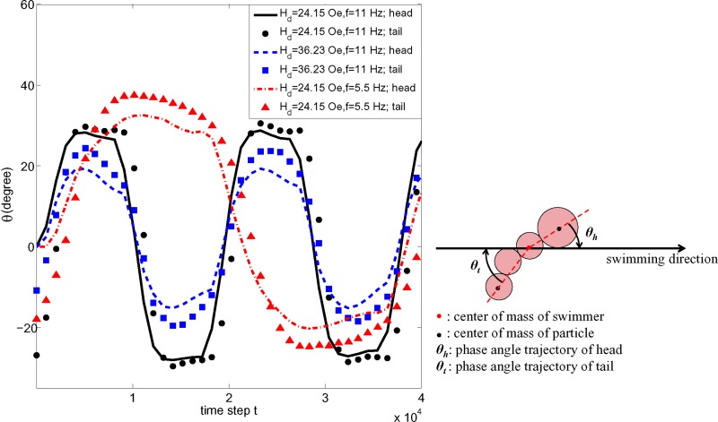
The evolutions of the Strouhal numbers of the S3L1 swimmer in various controlling parameters are depicted in Fig. 9. All swimmers are subjected to an identical dynamical perpendicular field strength of Hp = 25.08 Oe with various directional field strengths and oscillating frequencies. It is well known that the Strouhal numbers of effective natural swimmers ranged between 0.25 and 0.4.26–28 Apparently, the S3L1 swimmer manipulated under the weaker field strength of Hd = 24.15 Oe with a frequency f = 11 generates the most ineffective propulsion and results in an average St of 26.7. More propulsive efficiency is obtained from lowering the frequency to f = 5.5 Hz or increasing the directional field strength to Hd = 36.23 Oe, resulting in the lower average Sts of 5.9 and 2.1, respectively. Through a more detailed inspection of the oscillating trajectories for the S3L1 swimmer manipulated under different controlling parameters, we can further understand the mechanism of the distinct performances. Fig. 10 compares the oscillating trajectories between the head and tail of S3L1 swimmer under the influence of varying field strengths and frequencies. As shown in Fig. 10, the S3L1 swimmer manipulated by a stronger directional field strength of Hd = 36.23 Oe leads to more asynchronous phase angle trajectories between head and tail. This more asymmetric oscillation resulting in a wiggling motion as a travelling sine is favorable for propulsive efficiency. In addition, the superior efficiency can also be explained physically by the definition of the Strouhal number, i.e., St = fA/U. Li et al.17 suggested an external field of a stronger directional component tends to dampen the overall oscillating pattern. Therefore, it can be expected that the lower amplitude associated with the stronger directional field may reduce the average St and increase the propulsive efficiency. On the other hand, when the swimmer is subjected to a weaker Hd of 24.15 Oe, the trajectories of the head and tail particle appear more synchronous. In addition, the trajectory pattern apparently deviates from the original sinusoidal oscillation. As a result, the swimmer oscillating as a rigid body leads to inefficient propulsion.
FIG. 9.
Evolutions of correspondent values of the Strouhal number for S3L1 swimmer subjected to different directional field strength and oscillating frequencies.
FIG. 10.
Phase angle trajectories of the head and tail of the S3L1 swimmer under various field strengths and oscillating frequencies within 4 × 10⁴ arbitrarily oscillating time steps.
Using the definition of the Strouhal number, we can understand that the lower frequency may reduce the St and increase the propulsive efficiency. However, the swimmer or chain oscillating with the external field with lower frequency shows higher amplitude, as depicted in Fig. 10. This counter effect may increase the St, and therefore the average St for the swimmer at a lower frequency may be higher than in an external field of a stronger directional component.
The effect of the other controlling parameter on the swimmer's propulsive efficiency is discussed via various configuration of the swimmer. Table I displays the corresponding moving efficiencies of the three types of microswimmers, as shown in Fig. 7. Under an identical field strength of Hd = 24.15 Oe, Hp = 36.23 Oe, and frequency of f = 11 Hz, both the experimental and numerical values indicate the most efficient configuration is the S2L2 swimmer. Qualitatively, the numerical patterns of the swimmers and propulsive efficiency show very close agreements with the experimental results. Finally, such a numerical model provides a rapid way of determining the more efficient configuration of swimmers for biomedical applications.
TABLE I.
Average Strouhal numbers (Stav) of different configurations of swimmers as shown in Fig. 7. For effective natural swimmers, the Strouhal numbers ranged between 0.25 and 0.4.26–28 Both experimental and numerical results indicate that the most effective propulsion is generated by the S2L2 swimmer.
| Swimmers | S2L1 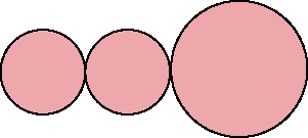
|
S3L1 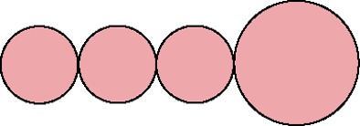
|
S2L2 
|
|---|---|---|---|
| Stav (experiment) | 328 | 36.8 | 20.57 |
| Stav (simulation) | 55.24 | 26.7 | 10.9 |
VI. CONCLUSIONS
In this study, the motions of magnetic microbead chains and swimmers subjected to an oscillating field are analyzed numerically and experimentally. The hybrid method of the lattice Boltzmann method, immersed boundary method, and discrete particle method are implemented to simulate the behaviors of these particular magnetic microdevices. The patterns of the structural stability and instability of the oscillating chain simulated by the numerical scheme show great similarities with those observed from video-microscopy experiments. In addition, the flow properties around the magnetic microchain and magnetic microswimmer, such as the pressure distribution of the flow, were investigated from the simulation results. It was found that the strong shear force acting on the chain due to the gradient of the pressure leads to the rupture. Moreover, the global criterion for rupture instability given by the value of N × Mn1/2 is qualitatively confirmed by simulations. The calculations for the interaction forces using the numerical method enable us to consider both hydrodynamic and magnetic interactions in the oscillating chains.
The influences of the controlling parameters on the swimmer's propulsive efficiency defined by the Strouhal number are thoroughly discussed in this study as well. Swimmers in the presence of a stronger directional field strength and higher oscillating frequency result in more asynchronous phase angle trajectories between head and tail. Such a greater asymmetric oscillation is favorable for propulsive efficiency. On the other hand, the efficiency of swimmers with different number and size beads were examined by experiments and simulations. The swimmer with the most efficient propulsion predicted by the numerical method is consistent with the experimental counterpart. In conclusion, the 3D hybrid numerical method provides an efficient method for our experimental setup to experimentally manipulate an oscillating magnetic bead chain and design the optimum microswimmer for applications in biotechnology.
ACKNOWLEDGMENTS
Financial support from the Ministry of Science and Technology of Republic of China (Taiwan) through Grant Nos. NSC 102-2221-E-009-051-MY3 and MOST 104-2218-E-606-001 is acknowledged.
References
- 1. Goubault C., Jop P., Fermigier M., Baudry J., Bertrand E., and Bibette J., Phys. Rev. Lett. 91, 260802 (2003). 10.1103/PhysRevLett.91.260802 [DOI] [PubMed] [Google Scholar]
- 2. Cebers A., Curr. Opin. Colloid Interface Sci. 10, 167 (2005). 10.1016/j.cocis.2005.07.002 [DOI] [Google Scholar]
- 3. Biswal S. and Gast A., Anal. Chem. 76, 6448 (2004). 10.1021/ac0494580 [DOI] [PubMed] [Google Scholar]
- 4. Kang T. G., Hulsen M. A., Anderson P. D., den Toonder J. M. J., and Meijer H. E., Phys Rev E 76, 66303 (2007). 10.1103/PhysRevE.76.066303 [DOI] [PubMed] [Google Scholar]
- 5. Roy T., Sinha A., Chakraborty S., Ganguly R., and Puri I., Phys Fluids 21, 027101 (2009). 10.1063/1.3072602 [DOI] [Google Scholar]
- 6. Dreyfus R., Baudry J., Roper M., Fermigier M., Stone H., and Bibette J., “ Microscopic artificial swimmers,” Nature 437, 862 (2005). 10.1038/nature04090 [DOI] [PubMed] [Google Scholar]
- 7. Li Y. H., Sheu S. T., Pai J. M., and Chen C. Y., J. Appl. Phys. 111, 07A924 (2012). 10.1063/1.3675269 [DOI] [Google Scholar]
- 8. Li Y. H., Lin H. C., and Chen C. Y., IEEE Trans. Magn. 49(7), 4120 (2013). 10.1109/TMAG.2013.2241028 [DOI] [Google Scholar]
- 9. Dufva M. and Christensen C. B., Expert Rev. Proteomics 2(1), 41–48 (2005). 10.1586/14789450.2.1.41 [DOI] [PubMed] [Google Scholar]
- 10. Melle S., Fuller G. G., and Rubio M. A., Phys. Rev. E 61, 4111 (2000). 10.1103/PhysRevE.61.4111 [DOI] [PubMed] [Google Scholar]
- 11. Melle S., Calder'on O. G., Rubio M. A., and Fuller G. G., J. Non-Newtonian Fluid Mech. 102, 135 (2002). 10.1016/S0377-0257(01)00174-4 [DOI] [Google Scholar]
- 12. Melle S., Calder'on O. G., Fuller G. G., and Rubio M. A., J. Colloid Interface Sci. 247, 200 (2002). 10.1006/jcis.2001.8087 [DOI] [PubMed] [Google Scholar]
- 13. Melle S., Calder'on O. G., Rubio M. A., and Fuller G. G., Phys. Rev. E 68, 041503 (2003). 10.1103/PhysRevE.68.041503 [DOI] [PubMed] [Google Scholar]
- 14. Gao Y., Hulsen M. A., Kang T. G., and den Toonder J. M. J., Phys. Rev. E 86, 041503 (2012). 10.1103/PhysRevE.86.041503 [DOI] [PubMed] [Google Scholar]
- 15. Yadav A., Calhoun R., Phelan P., Vuppu A. K., Garcia A. A., and Hayes M., IEE Proc. Nanobiotechnol. 153, 145 (2006). 10.1049/ip-nbt:20060009 [DOI] [PubMed] [Google Scholar]
- 16. Krishnamurthy S., Yadav A., Phelan P., Calhoun R., Vuppu A., Garcia A., and Hayes M., Microfluid. Nanofluid. 5, 33 (2008). 10.1007/s10404-007-0214-z [DOI] [Google Scholar]
- 17. Li Y. H., Chen C. Y., Sheu S. T., and Pai J. M., Microfluid. Nanofluid. 13, 579 (2012). 10.1007/s10404-012-0974-y [DOI] [Google Scholar]
- 18. Li Y. H., Lin H. C., and Chen C. Y., Microfluid. Nanofluid. 14, 831 (2013). 10.1007/s10404-012-1094-4 [DOI] [Google Scholar]
- 19. Li Y. H., Bansal E., and Chen C. Y., Magnetohydrodynamics 50(1), 19 (2014). [Google Scholar]
- 20. Lin H. C., Li Y. H., and Chen C. Y., Microfluid. Nanofluid. 17(1), 73 (2014). 10.1007/s10404-013-1286-6 [DOI] [Google Scholar]
- 21. McNamara G. and Zanetti G., Phys. Rev. Lett. 61, 2332 (1988). 10.1103/PhysRevLett.61.2332 [DOI] [PubMed] [Google Scholar]
- 22. Peskin C. S., Acta Numer. 11, 479–517 (2002). 10.1017/S0962492902000077 [DOI] [Google Scholar]
- 23. He X. and Luo L. S., Phys. Rev. E 55(6), R6333 (1997). 10.1103/PhysRevE.55.R6333 [DOI] [Google Scholar]
- 24. Chen S., Wang Z., Shan X., and Doolen G. D., J. Stat. Phys. 68(3–4), 379–400 (1992). 10.1007/BF01341754 [DOI] [Google Scholar]
- 25. Biswal S. and Gast A., Phys. Rev. E 69, 041406 (2004). 10.1103/PhysRevE.69.041406 [DOI] [PubMed] [Google Scholar]
- 26. Triantafyllou G. S., Triantafyllou M. S., and Grosenbaugh M. A., J. Fluids Struct. 7, 205–224.(1993). 10.1006/jfls.1993.1012 [DOI] [Google Scholar]
- 27. Taylor G. K., Nudds R. L., and Thomas A. L. R., Nature 425, 707–711 (2003). 10.1038/nature02000 [DOI] [PubMed] [Google Scholar]
- 28. Eloy C., J. Fluids Struct. 30, 205–218 (2012). 10.1016/j.jfluidstructs.2012.02.008 [DOI] [Google Scholar]


