Abstract
Selective RF pulses are commonly designed with the desired profile as a low pass filter frequency response. However, for many MRI and NMR applications, the spectrum is sparse with signals existing at a few discrete resonant frequencies. By specifying a multiband profile and releasing the constraint on “don’t-care” regions, the RF pulse performance can be improved to enable a shorter duration, sharper transition, or lower peak B1 amplitude. In this project, a framework for designing multiband RF pulses with improved performance was developed based on the Shinnar-Le Roux (SLR) algorithm and convex optimization. It can create several types of RF pulses with multiband magnitude profiles, arbitrary phase profiles and generalized flip angles. The advantage of this framework with a convex optimization approach is the flexible trade-off of different pulse characteristics. Designs for specialized selective RF pulses for balanced SSFP hyperpolarized (HP) 13C MRI, a dualband saturation RF pulse for 1H MR spectroscopy, and a pre-saturation pulse for HP 13C study were developed and tested.
Keywords: RF pulse design, Shinnar-Le Roux algorithm, convex optimization, multiband, improved pulse performance, generalized flip angle
Graphical abstract
Introduction
Multiband RF pulse designs have been previously used in hyperpolarized (HP) 13C MRI to yield different flip angles to substrates and metabolites (1-3). Combining multiband RF pulses with spectroscopic imaging readouts has been demonstrated successfully for improved observation of metabolic activity with higher SNR and slower signal decay (3). In HP 13C MRI, the signal arises only from injected substrate and its metabolites. For many other applications in MRI and NMR, the spectrum is sparse as well. For example in 1H MRI, the spectrum is dominated by water and lipid resonant peaks. The RF pulse profile is important only for frequencies where there are signals and thus there is substantial flexibility in terms of pulse design when there is sparsity in the spectral domain. Commonly, selective RF pulses are designed with profiles similar to a low-pass filter frequency response. In other words, the stopband and “don’t-care” region are treated equally.
In this work, we introduce a multiband RF pulse design framework with the goal of optimizing pulse performance and enabling broader applications. It only specifies the desired profile around the specific resonance frequency of each compound, and releases the unnecessary constraints of don’t-care regions. Pulse performance can be improved with this lesser constraint thus enabling shorter pulse duration, sharper profile transition, or lower peak B1 amplitude.
RF pulse design is commonly performed with the Shinnar-Le Roux (SLR) algorithm (4) which addresses the nonlinearity of the Bloch equation at higher flip angles. The SLR algorithm reversibly transforms the RF pulse design problem to a finite impulse response (FIR) filter design problem that is well established and for which many methods exist. The SLR algorithm has been applied for designing single-band pulses with linear-phase or minimum-phase (4), for applications which require a spatially excited multiband profile (5), and for other non-linear phase profiles such as quadratic phase pulse (6,7). In this work, the SLR algorithm has been further extended to pulse design with multiband magnitude profiles, arbitrary phase profiles, and generalized flip angles. Note that some common assumptions in the SLR algorithm (4) are assumed here, such as ignoring relaxation during the RF pulse, which is a reasonable approximation for applications where RF pulse duration is much shorter than T1 and T2.
Three different pulses were designed: (1) RF pulse with shorter duration for spectrally selective balanced Steady State Free Precession (bSSFP) sequence, (2) dual-band saturation pulse with sharper transition for 1H MR spectroscopy (MRS) and (3) saturation pulse with significantly reduced stopband ripple for HP 13C pre-saturation sequence. Bloch simulations were used to assess all of the pulses, and the first two pulses were further evaluated with phantom imaging experiments.
Methods
Pulse Design
The SLR algorithm casts the RF pulse design to a FIR filter design problem. Design of a multiband RF pulse has no additional difficulties for the inverse SLR transform itself; instead, it requires a more sophisticated FIR filter design as the beta polynomial. In this work, we further release the constraint on the phase profile to improve design flexibility. An excited slice with linear phase can be refocused by a reversal of the slice select gradient. Non-linear phase pulse profiles, including minimum-phase, maximum-phase (4), and quadratic-phase (6,7), cannot be fully refocused. However, it is not a concern for applications such as saturation pulses, inversion pulses, spectrally selective 13C excitation pulses (3), and slab-selective pulses in 3D imaging (4).
RF pulse design in general is not necessarily a convex problem, and a global optimal solution may not be found. However, if the SLR algorithm assumptions can be met, the RF pulse design is a convex problem. The beta polynomial with a multiband magnitude frequency response and an arbitrary phase frequency response can be designed and optimized using spectral factorization within the convex optimization framework (2,8), followed by inverse SLR transform to achieve a RF pulse with optimized performance. The formulation of complex-coefficient filter design as a convex optimization problem is shown below, while the explanation of notation and more details can be found in Appendix 1.
| (1) |
To solve this problem we used CVX, a package for specifying and solving convex optimization (9,10). In the spirit of reproducible research and open-source research tools, we are providing the open source code, which can be downloaded from https://github.com/shanghong/Multiband-RF-pulse-Design.git
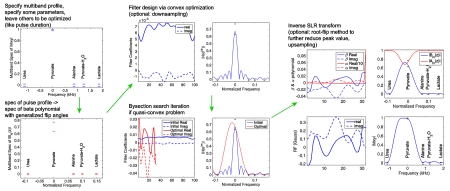
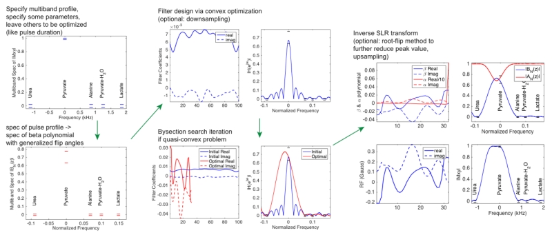
The design procedure is illustrated in Figure 1. We first specify the desired multiband excitation which includes the center frequency, bandwidth and flip angle for each band, all of which depend on the specific application and MR spectrum. Other parameters, including pulse duration, total energy, peak amplitude, profile ripple, and transition bandwidth can either be specified or left to be optimized. Then the specification of the RF pulse profile is converted to the specification of the beta polynomial, which is designed and optimized via convex optimization. Lastly the RF pulse is created by inverse SLR transform.
Figure 1.
(double column) Diagram of the design procedure. The example is of a pulse design for application 1, to design a multiband RF pulse with shortest duration used in bSSFP sequence.
Compared to previous studies (2,3), this work features a flexible trade-off among multiple RF pulse characteristics, such as pulse duration, peak amplitude, total energy, profile transition bandwidth, and profile ripple. The advantage of the convex optimization approach is to incorporate additional design criteria as long as they are also convex, such as total energy, peak amplitude, stopband ripple. Some characteristics are quasi-convex, such as transition bandwidth and pulse duration, which can be optimized by bisection search. Each iteration of the bisection search involves solving a convex optimization feasibility problem. Further details of incorporating convex constraints are in Appendix 1.
To generalize this design framework for broad applicability, arbitrary flip angles were allowed to be specified for each band. Pauly et al. (4) derived the parameter relations for 5 types of pulses: small-tip-angle pulse, 90° excitation pulse, 180° inversion pulse, 180° crushed spin-echo pulse, and 90° saturation pulse. With arbitrary flip angles, the parameter relations need to be generalized, especially determining the relationship between the beta polynomial FT ripple amplitudes and the pulse profile ripple amplitudes. Such SLR parameter relations with generalized flip angles have been studied before, however, previous work (11) is limited in that the effect of ripple in the alpha polynomial FT is neglected, and the transverse and longitudinal magnetization ripples are mixed together, while only one is of concern for most applications. Another study (12) used numerical inversion followed by an iterative refinement which makes the pulse design cumbersome and computationally intensive. In this work, a new general parameter relation of the SLR algorithm is derived. It first calculates the range of flip angles given the range of magnetization (specified by the ripple), then figures out the range of beta polynomial FT based on flip angle. More details are given in Appendix 2. This method is accurate, easy to calculate, and intuitive. Note that this method only achieves accurate profile amplitude ripple when the B1 field is calibrated correctly. In practice the B1 field is usually non-uniform, and pulse profile amplitude errors may be sensitive to B1 deviation, which is a common problem for SLR pulse design, and will be discussed in more detail in the Results section.
Application 1: Selective RF pulses in balanced SSFP
When using a selective RF pulse in a bSSFP sequence, minimum RF pulse duration is desired to reduce TR, minimize banding artifacts, and reduce total scan time. The goal is to design selective RF pulses with the minimum duration for a HP 13C bSSFP sequence at 14T to image 13C-labeled pyruvate, lactate, and urea individually. HP 13C MRI with dissolution Dynamic Nuclear Polarization (DNP) has been shown to provide metabolic information in vivo by detecting endogenous, nontoxic 13C-labeled probes (13-15). Spectrally selective bSSFP sequences for multiple compound HP 13C metabolic mapping have been developed with non-selective RF pulse (16-18). However, it has numerous problems, such as narrow passband and suboptimal SNR. Integrating a selective RF pulse can contribute to the overall spectral selectivity and allow optimizing other performance.
For the HP 13C studies with copolarized [1-13C]pyruvate and [13C]urea as the injected substrate, the spectrum is sparse including resonance peaks of pyruvate, pyruvate hydrate, urea, and metabolic products (considering lactate and alanine in this case, bicarbonate is neglected). A multiband profile is specified for exciting one compound (flip angle = 60°) while not exciting others and releasing unnecessary constraints elsewhere, which is the key for minimizing pulse duration. The frequency range of each band is specified based on the experimental setup, especially the shimming capability (±50Hz in this work). Excitation magnetization ripple was specified as 0.01 for the passband and 0.005 for the stopband. A standard minimum-phase SLR pulse and a linear-phase multiband pulse were also designed as comparison.
Application 2: Dualband saturation RF pulse
For some applications of 1H MRS, suppression of two or more compounds is desired. As a proof-of-concept, a saturation pulse was designed to suppress water (90°) and perform metabolite editing by suppressing glutamine/glutamate/NAA (120°) without perturbing peaks in between for 3T 1H MRS. Saturation pulses with flip angles larger than 90° are often used to offset rapid T1-dependent signal recovery (19). In this work, the flip angle was chosen arbitrarily as a feasibility demonstration. The goal was to design a dualband saturation pulse with the sharpest transition to minimize suppression of useful compounds, with other parameters fixed, including duration = 26ms, and in-slice / out-of-slice ripple = 0.05 / 0.001.
Application 3: Small ripple saturation RF pulse
A spectrally selective pre-saturation pulse sequence has been developed to suppress unwanted resonance in HP 13C studies during the bolus infusion (20). The saturation pulse was repeated multiple times throughout the infusion to compensate for B1 inhomogeneity and flow of 13C-labeled agent. Therefore, the out-of-slice ripple needs to be very small to minimize the accumulated effect of perturbing desired HP signal. A saturation RF pulse with reduced out-of-slice ripple was designed within this new framework by releasing the constraint on the saturation profile at frequencies outside of the band around the desired resonance peak.
MR experiments
For the selective RF pulse in bSSFP (application 1), phantom tests were performed on a 14T vertical NMR system (Varian Inc, Palo Alto, CA, USA). The excitation profile was measured by shifting the center frequency and measuring signal amplitude for a 13C enriched urea phantom. Three RF pulses were used in a custom 3D bSSFP sequence for sequential acquisition of urea, lactate, and pyruvate images. The minimum duration of the lactate-only pulse is longer than the other two. To simplify the implementation, we set the lactate-only pulse duration for all three pulses. BSSFP sequence parameters included: FOV = 64×32×32mm; matrix size = 32×16×16; TR = 4ms; TE = 2ms; scan time = 1s/image; flip angle = 60°; readout bandwidth = 21 kHz. A HP phantom test was performed with HP [1-13C]pyruvate syringe and HP [13C]urea syringe separately.
For the dualband saturation pulse (application 2), experiments with a water syringe were performed on a 3T clinical MRI scanner (GE Healthcare, Waukesha, WI, USA) using a shimming gradient (0.04 G/cm) to create off-resonance along one spatial dimension. The saturation pulse was applied followed immediately by a 1D gradient echo sequence (with phase encoding turned off), to get the 1D spatial profile, which mimics the spectral profile. The water syringe, shimming gradient and readout gradient were all along z direction. Parameters include FOV = 12cm, resolution = 0.6mm, TE = 4ms, readout bandwidth = 50kHz. A windowed sinc excitation RF pulse was used (without slice selective gradient), with duration = 0.8ms, Time-Bandwidth-Product = 4, flip angle = 90° to uniformly excite within [−1000 1000]Hz. The saturation pulse is very sensitive to B1 transmit gain calibration, which was first calibrated automatically, then manually fine tuned.
Results
Application 1 RF pulses for balanced SSFP
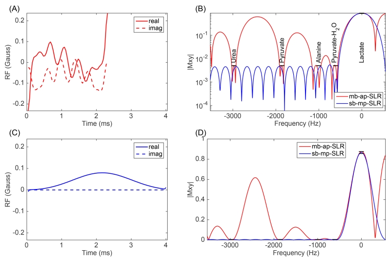
Three RF pulses were designed for exciting urea, lactate, and pyruvate, respectively. The lactate-only pulse is shown in Figure 2 (A) as an example, with the Bloch simulation of the excitation profile shown in Figure 2 (B, D). The pulse duration is listed in Table 1, and compared to a standard single-band minimum-phase SLR pulse design, as shown in Figure 2 (C). With this new optimized RF pulse, the total scan time of our 3D bSSFP acquisition with 2mm isotropic resolution is reduced by at least 430ms to be within 1s, to enable real-time within-breath preclinical imaging.
Figure 2.
(1.5 column) (A) Multiband arbitrary-phase lactate-only RF pulse (mb-ap-SLR) for bSSFP 13C sequence at 14T with shortest duration is compared to a standard single-band minimum-phase SLR pulse (sb-mp-SLR) (C). For both pulses, Bloch simulations are shown for the magnitude excitation profile in logarithmic scale (B), and linear scale (D). The specification of multiband profile is highlighted in black in (B).
Table 1.
For selective RF pulse used in bSSFP 13C sequence at 14T, comparing pulse duration of optimal multiband design to standard minimum-phase SLR pulse design.
| RF pulse | multiband pulse duration (ms) |
minimum-phase pulse duration (ms) |
Duration reduction |
|---|---|---|---|
| lactate-only | 2.32 | 4.00 | 42% |
| pyruvate-only | 1.72 | 3.10 | 45% |
| urea-only | 1.16 | 1.85 | 37% |
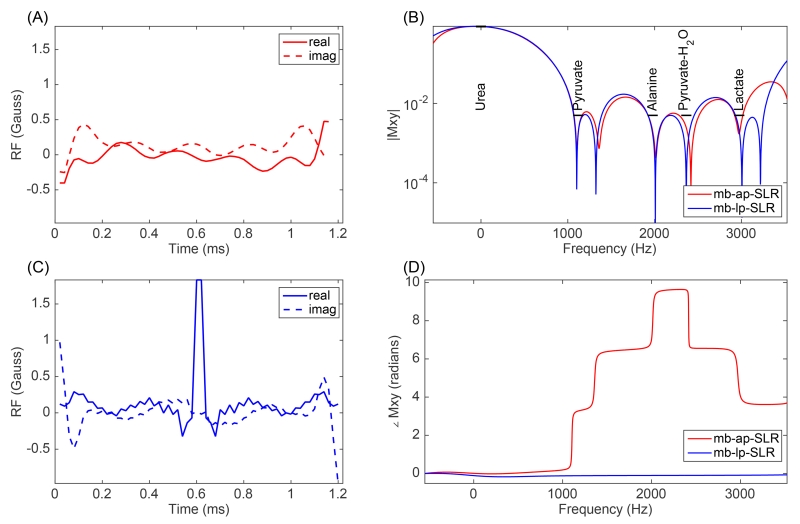
Another feature of these pulses is the arbitrary phase profile. To illustrate the improvement by releasing the linear phase constraint, the Bloch simulation was carried out to compare multiband arbitrary-phase pulses and multiband linear-phase pulses. One example of a urea-only pulse is shown in Figure 3. To achieve similar multiband profile and similar pulse duration, the arbitrary-phase pulse has significantly reduced peak amplitude and pulse power.
Figure 3.
(1.5 column) (A) A multiband arbitrary-phase urea-only RF pulse (mb-ap-SLR) for bSSFP 13C sequence at 14T with shortest duration, is compared to a multiband linear-phase SLR pulse (mb-lp-SLR) (C). For both pulses, Bloch simulations are shown for the magnitude excitation profile (B) and the phase profile adjusted for the linear phase component (D). The specification of the multiband profile is highlighted in black in (B). The arbitrary-phase pulse has peak B1 value of 0.477 Gauss (510 Hz), while the linear-phase pulse has peak B1 value of 1.831 Gauss (1961 Hz).
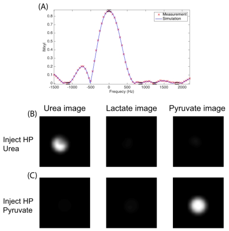
The measured excitation profile matched closely with simulation and design specifications. One example of a pyruvate-only pulse is shown in Figure 4 (A). Using these RF pulses in the bSSFP sequence resulted in good selectivity with HP phantom test, as shown in Figure 4 (B,C). More specifically, with the HP 13C urea phantom, the bSSFP acquisition selecting lactate/pyruvate demonstrated a contaminant signal less than 3.7% / 6.1% of actual signal in the urea acquisition. With the HP 13C pyruvate phantom, the bSSFP acquisition selecting lactate/urea showed a contaminant signal less than 4.9% / 2.8% of actual signal in the pyruvate acquisition.
Figure 4.
(1.5 column) (A) Simulated and measured excitation profile of the pyruvate-only pulse plotted with the profile specifications (black lines). For the 3D bSSFP imaging with selective RF pulses on HP 13C phantom at 14T, urea / lactate / pyruvate images are shown after injecting HP urea (B). The same sequence but injecting HP pyruvate is shown in C. One central axial slice of the 3D images is displayed in B and C.
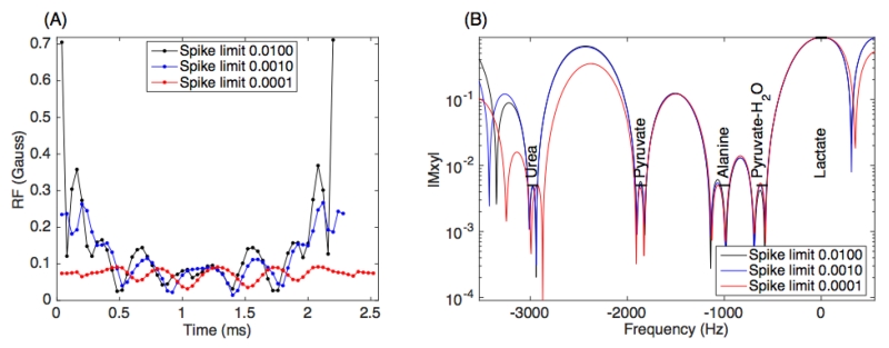
BSSFP RF pulses with minimum duration usually have higher peak amplitude. For example the optimal lactate-only pulse has peak amplitude of 0.237 Gauss (254 Hz), 3.0-fold higher compared to a standard minimum-phase SLR pulse. Also note that the first and last samples have the highest amplitudes. This peak amplitude is still within the MR system limits in our experimental setup, however, it could be a concern for other systems. One advantage of this RF pulse design framework is allowing an easy trade-off of pulse duration and peak amplitude by setting appropriate constraints on the end-spike as illustrated in Appendix 1. As a demonstration, 3 RF pulses were designed with different constraints on end-spike, which resulted in significantly reduced peak amplitude and slightly longer pulse duration, as shown in Figure 5. The limitation of this method for controlling peak amplitude is that it may not work for RF pulse designs with large time-bandwidth-products, where the peak amplitude may not be at the first or last sample.
Figure 5.
(1.5 column) bSSFP lactate-only RF pulse design with different end-spike (peak amplitude) constraint (A), and the corresponding simulated profiles (B). The pulse in blue is the same as the multiband pulse in Figure 2(A).
Application 2 Dualband saturation RF pulse
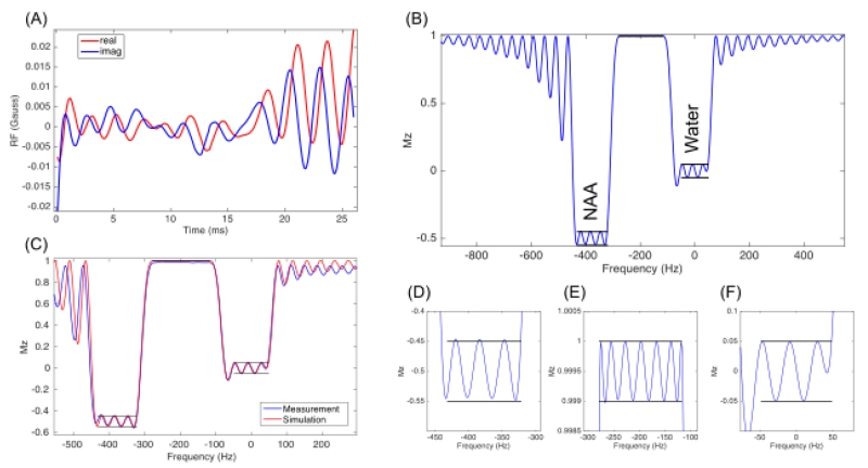
A dualband saturation RF pulse for 1H MRS at 3T was designed with input specification shown in Figure 6 (B). The resultant pulse (Figure 6 (A)) has a pulse profile (Figure 6 (B)) as determined with Bloch simulation. Zoomed-in regions for the response in each of the input specified bands are shown in Figure 6 (D-F). The simulated profile meets the design specification exactly. Note that the profile of the band with 120° flip angle (Figure 6 (D)) also meets the design specification accurately, which demonstrates the proposed SLR parameter relation with generalized flip angles, as illustrated in Appendix 2. If simply using the parameter relation for 90° saturation pulse (4), the resulting profile will have a large deviation from the design specification.
Figure 6.
(Double column) Dualband saturation pulse for suppression of both water (90°) and glutamine/glutamate/NAA (120°) for 1H MRS at 3T. Pulse waveform (A). Bloch simulation of the saturation profile (B), with the predefined specification highlighted in black. Zoomed in plots of each band (D, E, F). The measured profile agrees well with the simulated result (C).
The transition bandwidth of this pulse is 44 Hz. For comparison in terms of transition bandwidth, an alternative approach was implemented to design two single-band minimum-phase beta polynomials individually, then sum them and apply inverse SLR transforms to generate a dualband saturation RF pulse. This simpler approach results in a pulse with a transition of 62Hz, 41% larger than the optimal pulse. Measured saturation profile matches well with simulation and design specifications as shown in Figure 6 (C). The measured profile has some distortion for off-center spins due to the non-linearity of the shimming gradient.
Application 3: Small ripple saturation RF pulse
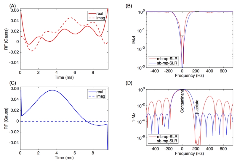
The saturation pulse with reduced stopband ripple for suppression of undesired resonances in HP 13C-lactate studies was designed and shown in Figure 7 (A). The Bloch simulation of the pulse profile is shown in Figure 7 (B, D), together with the specified bands. A standard maximum-phase SLR pulse was used for comparison, as shown in Figure 7 (C). The standard SLR pulse meets the design spec of 0.001 stopband ripple, while the improved design has 10−6 stopband ripple, which is 3 orders of magnitude smaller. The 0.001 stopband ripple is adequately low for one single pulse performance, however it may still cause signal loss when the saturation pulse is repeated multiple times. If the RF pulse is repeated 32 times as a pre-saturation pulse, the standard maximum phase pulse will cause 3.151% loss of desired HP lactate signal, while the optimal pulse will only cause 0.003% loss.
Figure 7.
(1.5 column) (A) Saturation RF pulse with extremely low stopband ripple (mb-ap-SLR) used in HP 13C Lactate study with repetitive pre-saturation pulse, was compared to a standard maximum-phase SLR pulse (sb-mp-SLR) (C). For both pulses, Bloch simulations of the saturation profile are shown for passband (B) and stopband (D). The specification of the multiband profile is highlighted in black in (B, D).
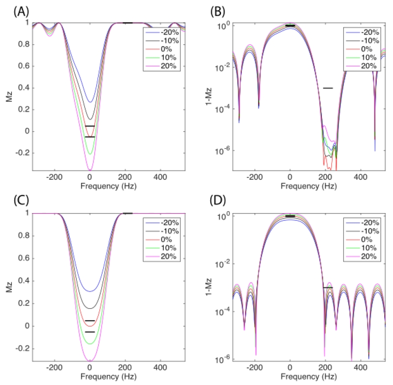
Bloch simulation was also carried out with a non-ideal B1 calibration (scaled RF pulse). As shown in Figure 8 (A, B), the saturation profile is sensitive to B1 field, especially for passband. This is also why this saturation pulse was repeated multiple times to compensate for B1 sensitivity. The stopband ripple is still very low given the range of B1 field. Also note that such B1 sensitivity is a common problem for all SLR pulse design, as shown in Figure 8 (C, D).
Figure 8.
(1.5 column) Bloch simulation of 13C saturation RF pulse profile with non-ideal B1 transmit field calibration. Each profile corresponds to a scaled RF pulse. The profile of optimized pulse with reduced stopband ripple is shown in (A, B), while the maximum-phase SLR pulse profile is shown in (C, D). The passband is visualized in (A, C) with linear scale while the stopband is visualized in (B, D) with log scale. The specification of the multiband profile is highlighted in black.
Discussion
In this work, we show that RF pulse performance can be improved beyond the limits of previous SLR pulse design methods (4) by exploiting the sparsity of spectrum and specifying a multiband profile. There is no longer an analytical relation for trade-off of pulse performance as in (4), but it still allows an easy trade-off of different characteristics via the convex optimization approach. Tighter constraints on one parameter will usually sacrifice other performance metrics.
One advantage of this framework is that minimal work is required of the pulse designer. The pulse designer only needs to specify which parameter should be optimized and this design framework will figure out the optimal solution automatically. By comparison, the conventional pulse design may need multiple iterations to fine tune some parameters to meet the design specifications. For example, in application 3, we specified to optimize the stopband ripple of the saturation pulse, and this framework created a pulse with global optimal solution in terms of stopband ripple. Previous SLR pulse design methods necessitated an explicit declaration of the value of stopband ripple. This value may need to be fine tuned manually multiple times to obtain a reasonably good result, but this does not guarantee we have found the global optimal solution. Although this framework using convex optimization requires longer computation time, we have found that the total time spent on pulse design is actually shorter compared to conventional approaches that manually iterate parameters.
A practical consideration is how many samples to use for the RF pulse and FIR filter design. The SLR algorithm assumes each hard subpulse is small (flip angle by each sample in the RF pulse), so the sampling rate of the RF pulse needs to be adequately large. But solving convex optimization problem with large number of filter coefficients may take too much time. In this work we solved this problem by designing the FIR filter after downsampling the design specifications. Once an optimal FIR filter is designed, we apply upsampling before the inverse SLR transform. Thus, the design process is faster, though the accuracy of the profile degrades slightly. Another reason underlying this downsampling-upsampling step is that we can apply the root-flip method to further reduce the peak amplitude (21), which becomes numerically challenging and potentially ill-conditioned when computing high-degree polynomial roots. Note that factoring high-degree polynomials can be done accurately and fast in some special scenarios with real coefficient polynomials (22), and it has been applied for the root-flip method for RF pulse design to reduce peak amplitude (23). This method may not work well for general polynomials such as the complex coefficient polynomials in this case. However the method proposed in (22) to construct a polynomial from its roots can still be applied here to significantly reduce computation error.
Though focused on spectrally selective RF pulses in this work, this method can also be applied for spatially selective RF pulses. For example, for outer volume suppression pulses we could release the constraint on the profile outside of the subject to reduce the transition bandwidth (24).
One limitation of this framework is that the computation time of an optimal FIR filter using the external convex optimization solver (CVX) is up to 1 minute, thus limiting use of this tool in real time during scan prescription. However, for those applications where an optimized RF pulse is desired with multiband profile, the RF pulse can be designed in advance off-line with a careful setting of parameters. For off-line RF pulse design, other design methods exist, such as optimal control algorithm, which offers increased flexibility and may achieve better performance such as increased B1 insensitivity (25).
Conclusion
A framework for general RF pulse design was developed using the SLR algorithm and convex optimization. This algorithm can create RF pulses with multiband magnitude profile, arbitrary phase profile, and generalized flip angle. Spectral sparsity was exploited to further improve pulse performance in terms of pulse duration, peak amplitude, total energy, transition width, or profile ripple, with flexible trade-offs. We present example designs for shorter duration pulses for a bSSFP 13C sequence at 14T; a dualband saturation pulse with sharper transition widths for 1H MRS at 3T; and a saturation pulse with extremely low stopband ripple for suppression of undesired resonances in HP 13C studies.
Highlights.
Spectral sparsity was exploited to improve RF pulse performance by specifying a multiband profile.
A framework for general RF pulse design was developed using the SLR algorithm and convex optimization with flexible trade-offs.
It can create RF pulses with multiband magnitude profile, arbitrary phase profile, and generalized flip angle.
We present example designs for shorter duration pulses for a bSSFP 13C sequence at 14T; a dualband saturation pulse with sharper transition widths for 1H MRS at 3T; and a saturation pulse with extremely low stopband ripple for suppression of undesired resonances in HP 13C studies.
Acknowledgements
The authors acknowledge funding support from NIH grants P41EB013598, R01EB013427, R01EB017449, R00EB012064 and R01EB016741.
Appendix 1 FIR Filter Design via Convex Optimization
1.1 Direct formulation
Using the following definition of a finite impulse response (FIR) filter with complex coefficients,
| (1) |
then the filter frequency response by Fourier Transform is
| (2) |
The real and imaginary components will be
| (3) |
| (4) |
where
We can also define the square of magnitude of the frequency response as
| (5) |
where , D = DT ≽ 0
To setup the filter design problem with specification only of the magnitude of the frequency response, we can set upper and lower bounds over the frequency range Ω of interest.
| (6) |
For the upper bound, |H(ejω)|2 = xTDx ≤ (U(ejω))2 , which is a quadratic constraint.
However for the lower bound, |H(ejω)|2 = xTDx ≥ (L(ejω))2 , which is a non-convex constraint and makes this problem hard to solve.
1.2 Power spectrum and autocorrelation formulation
In the work by Wu and Boyd (8), the power spectrum R(ejω) (= |H(ejω)|2) is used instead of designing the frequency response directly, which is the Fourier transform of the autocorrelation coefficients, r(n):
| (7) |
where represents the complex conjugate. Also note that
To express this filter design formulation in a matrix, we first define y ∈ R(2N–1)*1 as
| (8) |
with which we can express the power spectrum as
| (9) |
where Bω = [1 2cos(ω … 2cos(ω(N – 1)) 2sin(ω) … 2sin(ω(N − 1))]T ∈ R(2N−1)*1
Then the frequency response magnitude constraint becomes
| (10) |
which is a linear constraint. Therefore, by changing variables to constrain the power spectrum, the original nonconvex problem is converted into a convex problem (8).
This problem has infinite number of constraints at each frequency. The constraints can be approximated by sampling the frequency to make a finite number of constraints. The frequency samples can be fixed as −π ≤ ω1 < … <ωm ≤ π (for example ωk = (k – m/2)π/(m/2), k = 1, 2, …, m). Choosing m >> N yields a good approximation (common rule-of-thumb: m = 15N).
Once an optimal solution is found, the FIR filter can be obtained via spectral factorization. The frequency response magnitude is . As the phase of the frequency response is typically not a concern, we can choose the minimum-phase (mp) filter for simplicity. The log-magnitude and phase of a mp filter are a Hilbert transform pair, which can be used to calculate phase, thus design the complete filter.
For the spectral factorization, R(ejω) ≥ 0,ω ∈ [−π, π] is a necessary and sufficient condition for the existence of h(n). If this does not hold for all ω ∈ [−π, π], especially between frequency samples, the spectral factorization will fail. As in reference (8), failure can be prevented by adding a safety margin with an appropriately small ε > 0:
| (11) |
1.3 Incorporate other constraints
One advantage of convex optimization is that additional constraints can be added easily if they are also convex. We have included the following additional constraints:
- Peak amplitude: A common problem for SLR RF pulse design is potential large spikes at first/last samples (so-called “Conolly wings”), especially for equal-ripple pulses. In some cases these end-spikes are the peak amplitude, which may go beyond the MRI system limits. In this work we added a constraint to limit end-spikes by empirically assuming that a beta polynomial with lower end-spike will generate a RF pulse with lower end-spike. We also assumed that the last and first value of the filter are either large or small simultaneously. We have found that these assumptions work well for most applications. This constraint is formulated as:
(12) - Total energy: We also want to minimize the total energy, which can be useful for reducing the Specific Absorption Rate (SAR). Based on Parseval’s theorem, this constraint can be expressed by
(13) Minimum stopband ripple: For some applications we want to minimize the stopband ripple, for example saturation RF pulses with many repetitions. If we define , ωi ∈ Ωstopband ⊆ [−π,π], then we want to minimize δ1.
- SLR magnitude constraint: In SLR algorithm, the two polynomials must satisfy the frequency response amplitude constraint |AN (z)|2 + |BN (z)|2 = 1, to be a valid representation of a rotation, as in reference (4). So the FIR as the beta polynomial, must satisfy |H(ejω)| ≤ 1 for ω ∈ [−π, π]. Similarly to adding a safety margin for the spectral factorization, we can also add a safety margin here to make sure this magnitude constraint holds for all frequencies, especially between frequency samples.
(14)
The entire filter design problem can be expressed as a convex optimization problem, including the additional constraints described above:
| (15) |
Appendix 2 SLR Parameter Relation with Generalized Flip Angles
When designing a RF pulse, we usually specify the desired pulse profile such as passband and stopband edges, flip angles, and passband and stopband ripples. Since the SLR algorithm reduces RF pulse design to a FIR filter design problem, then the corresponding specification on the FIR filter needs to be derived first. This is particularly important for the ripples specifications, in other words, the specifications of the range of the frequency response magnitude.
In this work the ripple is defined as the absolute value (a±δ) instead of relative value (a(1±δ)) as previously used in (4,11,12), because scaling can be confusing for multiband pulses with different flip angles in different bands.
For a RF pulse with selective excitation along the x direction, specified by flip angle θ(x), the final rotation state is
| (1) |
where n = [nx, ny, nz]T is the rotation axis. The two SLR polynomials are defined as AN(z) = z−N/2 αN and BN(z) = z−N/2 βN, where z = eiγGxdt, and so
| (2) |
For an excitation pulse, the initial magnetization lies along the longitudinal direction, and the profile of interest is transverse magnetization Mxy(x):
| (3) |
Given the range of magnetization profile amplitude, [|Mxy|min, |Mxy|max], we can calculate a range of flip angles, [θmin, θmax], by inverting equation 3. Then the range of |BN (z)| can be calculated easily by equation 2. Note that |BN(z)| = sin(θ/2) is an increasing function for θ ∈ [0 π), while |Mxy| = sin(θ) is not. So care must be taken for the first step. Also note that the ripple is usually non-symmetric about the desired value.
For saturation and inversion pulses, the initial magnetization is along the longitudinal direction, and the profile of interest is Mz(x):
| (4) |
Similarly, given the range of magnetization profile, [(Mz)min, (Mz)max], we can calculate the range of flip angle, [θmin, θmax], by inverting equation 4, then figure out the range of |BN(z)| by equation 2.
No approximation is used in this approach, so the result ripple relation is precise, and it requires negligible computation time. A similar approach for refocusing pulses can be easily derived based on a similar formulation in reference (4), which is not shown here.
Footnotes
Publisher's Disclaimer: This is a PDF file of an unedited manuscript that has been accepted for publication. As a service to our customers we are providing this early version of the manuscript. The manuscript will undergo copyediting, typesetting, and review of the resulting proof before it is published in its final citable form. Please note that during the production process errors may be discovered which could affect the content, and all legal disclaimers that apply to the journal pertain.
References
- 1.Schricker Amir A., Pauly John M., John Kurhanewicz, Swanson Mark G., Vigneron Daniel B. Dualband spectral-spatial RF pulses for prostate MR spectroscopic imaging. Magnetic resonance in medicine. 2001;46(6):1079–1087. doi: 10.1002/mrm.1302. [DOI] [PubMed] [Google Scholar]
- 2.Kerr AB, Larson PE, Lustig M, Cunningham CH, Chen AP, Vigneron DB, Pauly JM. Multiband spectral-spatial design for high-field and hyperpolarized C-13 applications; Proceedings of the 16th Annual Meeting of ISMRM; 2008.p. 226. [Google Scholar]
- 3.Larson Peder EZ, Kerr Adam B., Chen Albert P., Lustig Michael S., Zierhut Matthew L., Simon Hu, Cunningham Charles H., Pauly John M., John Kurhanewicz, Vigneron Daniel B. Multiband excitation pulses for hyperpolarized 13C dynamic chemical-shift imaging. Journal of magnetic resonance. 2008;194(1):121–127. doi: 10.1016/j.jmr.2008.06.010. [DOI] [PMC free article] [PubMed] [Google Scholar]
- 4.Pauly John, Patrick Le Roux, Dwight Nishimura, Albert Macovski. Parameter relations for the Shinnar-Le Roux selective excitation pulse design algorithm [NMR imaging] Medical Imaging, IEEE Transactions on. 1991;10(1):53–65. doi: 10.1109/42.75611. [DOI] [PubMed] [Google Scholar]
- 5.Cunningham Charles H., Wood Michael L. Method for improved multiband excitation profiles using the Shinnar-Le Roux transform. Magnetic resonance in medicine. 1999;42(3):577–584. doi: 10.1002/(sici)1522-2594(199909)42:3<577::aid-mrm21>3.0.co;2-e. [DOI] [PubMed] [Google Scholar]
- 6.Le Roux Patrick, Gilles Raymond J., McKinnon Graeme C., Carlier Pierre G. Optimized outer volume suppression for single-shot fast spin-echo cardiac imaging. Journal of Magnetic Resonance Imaging. 1998;8(5):1022–1032. doi: 10.1002/jmri.1880080505. [DOI] [PubMed] [Google Scholar]
- 7.Schulte Rolf F., Jeffrey Tsao, Peter Boesiger, Pruessmann Klaas P. Equiripple design of quadratic-phase RF pulses. Journal of Magnetic Resonance. 2004;166(1):111–122. doi: 10.1016/j.jmr.2003.10.009. [DOI] [PubMed] [Google Scholar]
- 8.Wu Shao-Po, Stephen Boyd, Lieven Vandenberghe. FIR filter design via semidefinite programming and spectral factorization. In Decision and Control, 1996; Proceedings of the 35th IEEE Conference on; IEEE. 1996.pp. 271–276. [Google Scholar]
- 9.Michael Grant, Stephen Boyd. CVX: Matlab software for disciplined convex programming, version 2.0 beta. 2013 Sep; http://cvxr.com/cvx.
- 10.Michael Grant, Stephen Boyd. In: Graph implementations for nonsmooth convex programs, Recent Advances in Learning and Control (a tribute to M. Vidyasagar) Blondel V, Boyd S, Kimura H, editors. Lecture Notes in Control and Information Sciences; Springer: 2008. pp. 95–110. http://stanford.edu/~boyd/graph_dcp.html. [Google Scholar]
- 11.Raddi A, Klose U. A Generalized Estimate of the SLR B Polynomial Ripples for RF Pulse Generation. Journal of Magnetic Resonance. 1998;132.2:260–265. doi: 10.1006/jmre.1998.1410. [DOI] [PubMed] [Google Scholar]
- 12.Lee Kuan J. General parameter relations for the Shinnar-Le Roux pulse design algorithm. Journal of Magnetic Resonance. 2007;186.2:252–258. doi: 10.1016/j.jmr.2007.03.010. [DOI] [PubMed] [Google Scholar]
- 13.Ardenkjær-Larsen Jan H., Björn Fridlund, Andreas Gram, Georg Hansson, Lennart Hansson, Lerche Mathilde H., Rolf Servin, Mikkel Thaning, Klaes Golman. Increase in signal-to-noise ratio of > 10,000 times in liquid-state NMR. Proceedings of the National Academy of Sciences. 2003;100(18):10158–10163. doi: 10.1073/pnas.1733835100. [DOI] [PMC free article] [PubMed] [Google Scholar]
- 14.Golman Klaes, Mikkel Thaning. Real-time metabolic imaging. Proceedings of the National Academy of Sciences. 2006;103(30):11270–11275. doi: 10.1073/pnas.0601319103. [DOI] [PMC free article] [PubMed] [Google Scholar]
- 15.Nelson Sarah J., John Kurhanewicz, Vigneron Daniel B., Peder EZ Larson, Harzstark Andrea L., Marcus Ferrone, Mark van Criekinge, et al. Metabolic imaging of patients with prostate cancer using hyperpolarized [1-13C] pyruvate. Science translational medicine. 2013;5(198):198ra108–198ra108. doi: 10.1126/scitranslmed.3006070. [DOI] [PMC free article] [PubMed] [Google Scholar]
- 16.von Morze, Cornelius Subramaniam Sukumar, Reed Galen D., Peder EZ Larson, Bok Robert A., John Kurhanewicz, Vigneron Daniel B. Frequency-specific SSFP for hyperpolarized 13C metabolic imaging at 14.1 T. Magnetic resonance imaging. 2013;31(2):163–170. doi: 10.1016/j.mri.2012.06.037. [DOI] [PMC free article] [PubMed] [Google Scholar]
- 17.Månsson Sven, Stefan Petersson J, Klaus Scheffler. Fast metabolite mapping in the pig heart after injection of hyperpolarized 13C-pyruvate with low-flip angle balanced steady-state free precession imaging. Magnetic Resonance in Medicine. 2012;68(6):1894–1899. doi: 10.1002/mrm.24183. [DOI] [PubMed] [Google Scholar]
- 18.Leupold Jochen, Sven Månsson, Stefan Petersson J, Jürgen Hennig, Oliver Wieben. Fast multiecho balanced SSFP metabolite mapping of 1H and hyperpolarized 13C compounds. Magnetic Resonance Materials in Physics, Biology and Medicine. 2009;22(4):251–256. doi: 10.1007/s10334-009-0169-z. [DOI] [PubMed] [Google Scholar]
- 19.Tran Tuan-Khanh C., Vigneron Daniel B., Napapon Sailasuta, James Tropp, Patrick Le Roux, John Kurhanewicz, Sarah Nelson, Ralph Hurd. Very selective suppression pulses for clinical MRSI studies of brain and prostate cancer. Magnetic resonance in medicine. 2000;43(1):23–33. doi: 10.1002/(sici)1522-2594(200001)43:1<23::aid-mrm4>3.0.co;2-e. [DOI] [PubMed] [Google Scholar]
- 20.von Morze C, Larson PEZ, Shang H, Vigneron DB. Suppression of unwanted resonances in hyperpolarized MR studies with neat [1-13C]lactic acid. Proc Intl Soc Mag Reson Med. 2014;22:2792. [Google Scholar]
- 21.Pickup Stephen, Xiaoning Ding. Pulses with fixed magnitude and variable phase response profiles. Magnetic resonance in medicine. 1995;33(5):648–655. doi: 10.1002/mrm.1910330509. [DOI] [PubMed] [Google Scholar]
- 22.Sitton Gary, Sidney Burrus C, Fox James W., Sven Treitel. Factoring very-high-degree polynomials. Signal Processing Magazine, IEEE. 2003;20(6):27–42. [Google Scholar]
- 23.Lustig M, Cunningham CH, Pauly JM. A Monte-Carlo algorithm for designing ultra-high time-bandwidth, minimum peak B1, selective saturation and inversion RF pulses; Proceedings of the ENC; Pacific Grove, California, USA. 2006. [Google Scholar]
- 24.Stikov Nikola, Mutapcic A, Pauly JM. Optimized Design of Single-sided Quadratic Phase Outer Volume Suppression Pulses for Magnetic Resonance Imaging; 11th Mediterranean Conference on Medical and Biomedical Engineering and Computing 2007; Springer Berlin Heidelberg. 2007. [Google Scholar]
- 25.Janich Martin A., Schulte Rolf F., Markus Schwaiger, Glaser Steffen J. Robust slice-selective broadband refocusing pulses. Journal of Magnetic Resonance. 2011;213(1):126–135. doi: 10.1016/j.jmr.2011.09.025. [DOI] [PubMed] [Google Scholar]


