Abstract
Background:
Orthopedics implants are important tools for treatment of bone fractures. Despite available recommendations for designing and making the implants, there are multiple cases of fracture of these implants in the body. Hence, in this study the frequency of failure of implants in long bones of lower extremities was evaluated.
Methods and Materials:
In this cross-sectional study, two types of fractured implants in the body were analyzed and underwent metalogical, mechanical, and modeling and stress-bending analysis.
Results:
The results revealed that the main cause of fractures was decreased mechanical resistance due to inappropriate chemical composition (especially decreased percentages of Nickel and Molybdenum).
Conclusions:
It may be concluded that following the standard chemical composition and use of optimal making method are the most important works for prevention of failure of implants.
Keywords: Implant, SEM, Optical Metallography, Quantometry
1. INTRODUCTION
Fracture of long bones would require the time for healing ranging from several weeks to months. Since the introduction of antibiotics, direct bone surgeries and fixation with metals have changed to a conventional method (1). Use of internal fixators has increased the rate of bone fracture treatment and decreased the time interval for normal life. This matter is not acceptable by majority of patients and may result in mental and somatic problems.
Regarding the increased use of internal fixators in recent years and diversity of available products, the failure of these tools has also increase. It may be seen as different forms including major deformity, mechanical fracture, corrosion, and avulsion from the bone (2). Also different factors are contributing for failure including inappropriate material and make-up, inappropriate fixator selection and surgical technique, and lack of consideration of optimal weighting by patient (2, 3). The failure before treatment completion is an important complex complication leading to numerous problems and Reoperation leading to costs and injuries (1).
Two different types of alloys including stainless steel 316 and pure titanium are two optimal materials for making the internal fixators introduced in ASTM and ISO standards (4-6). Regarding to optimal technique and fixator would result in higher tolerability and better healing (7). Since the failure rate has increased, this study was performed to determine the etiologies of implant fracture in patients with fractures of the implants of lower limbs’ long bones for better programming to reduce the rate of failure of fixators.
2. METHODS AND MATERIALS
In this cross-sectional study, two types of fractured implants in the body were analyzed and underwent metalogical, mechanical, and modeling and stress-bending analysis among 11 subjects among 21 total sample size attending to a referral academic hospital in 2013 and 2014 who had Reoperation for femoral and tibial bones repair. Background diseases such as osteoporosis, osteopenia, malignancy, diabetes mellitus, high-energy trauma, and the fixator types other than stainless steel and titanium were the exclusion criteria.
At first the fixators underwent quantometry to determine the weight percent of each one. This stage was performed by Spark Emission Spectrophotometer (Made in Germany) in environmental situations by standard of ASTM E406-81 and the results were compared with ISO-5832-1 amounts. Then optic metallography was performed by Optical Microscope. Determination of size of particles in microstructure of metal, cycle of thermal operation, production procedure and type of superficial operation, microstructrual cracks, and type of impurity in cross-section were the objectives in this study. The used chemical to determine the border of particles was, CuCl2, HCl, and alcohol. The experiment was performed in two sections of far and near. The photographs were in 1000×, 500×, 250×, and 100× views. The third matalological test was electron microscopy evaluation in which the cross-section was assessed by scanning electron microscope (SEM) to determine the fracture cause by evaluation of borders and lines and cracks and corrosions.
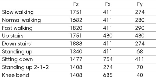
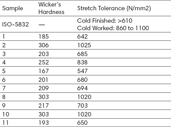
The goal of mechanical assessment was determination of mechanical tolerance of implant; the hardness of samples was measured and altered to stretch tolerance by experimental data. The hardness was measured by Macrohardness Tester by Wicker’s method. For alteration of hardness to stretch tolerance, reference data were used (11). The results were compared with stretch stress of implants in ISO5832 standard. By considering the large predicted stresses in DHS plaque, it underwent stress-strain analysis. For geometric modeling the Solidwork software was used and the model was completely made according to real sample. Stress analysis was performed by element method via ANSYS software. The borderline conditions were prepared with fixation of screws location and insertion of external forces to femoral head. Regarding difference of inserted forces on implants according to patients’ activity, the reference data were used (12) including the forces on femoral head in slow walking, normal walking, rapid walking, stair coming up and down, sitting, standing, dribbling, and bending and up righting the knee measured by sensor.
2.1. Chemical composition tests
For determination of chemical composition, the quantometry test was performed and the weight percent of elements of alloys were determined. This test was performed by Spark Emission Spectrometer (Made in Germany) in standard situation of ASTM E406-81.
2.2. Metallographic assessment
For microstructure analysis, the optical metallography was performed by optical microscope. Determination of particle size in microstructure of metal, thermal function cycle, production process, type of superficial performance, microstructural cracks, and evaluation of impurity particles on cross-sections were the goals for this test. Preparation of samples according to ASTM E 3-10 was in four stages including soft wearing, hard processing, final processing, and making H. The soft wear was performed by silicium carbide on special papers by three sizes including 320, 400, and 600 and using silicium carbide particles sizing of 33, 23, and 17 microns. The initial wearing was performed by moving the sample on a surface to make the scratches in an orientation. Then the sandpaper used to wear in 90-degree angle resulting in angular scratches. It was continued up to masking the scratches from previous stages. Then the samples were put in rotary cycle and processed homogenously by diamond powder of 6 micron size under significant pressure. In final process stage, the fine scratches and remaining bend layers were removed. In this stage Alumina powder (Gamma type) with 0.05 micron size was used. H formation stage was performed to determine the border of particles with putting the samples in a solution of CuCl2, HCl, and alcohol. The other used standards were ASTM E 407-07 for metal microH, ASTM E 883-02 for microscope imaging, and STM E 112-96 for measurement of mean particles size.
2.3. SEM tests
For samples number 10 and 11 the cross-sections were assessed by electron microscope device of Scanning Electro Microscope (SEM) to determine the cause of fracture by evaluation of cracks and fractures. The fracture surfaces were broken by a special diameter to be evaluated by microscope. The magnification amount for graphs of cross-section was from 100 to 1000.
2.4. Stress Analysis
Regarding complexity of loading of DHS implants and uncertainty about the stresses by segment method the stress-strain analysis was performed. For determination of type of loading and locking on the segments the data from study by Bergmann et al (8) was used. The locks were in holes for linkage of the screw and bone.
Final data analysis was performed by SPSS software (version 18.0). The percent for categorical and the mean and standard deviation were reported for numeric variables.
3. RESULTS
Results of our investigation are shown in Tables 1-6.
Table 1.
The Forces on femoral head in three orientations

Table 2.
Characteristics in patients

Table 3.
Chemical composition of samples

Table 4.
Hardness and stretch tolerance in samples

Table 5.
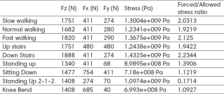
The amount of stress on implant and the ratio to allowed limit

Table 6.
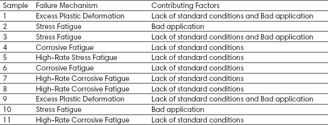
Causes of implant failure

Demographics
The samples were 11 cases after exclusion of 20 ones. 73% were male and 27% were female. The mean age was 35.8 ± 8.2 years (ranging from 21 to 52). The mean weight was 71.6 ± 5.4 kg and the mean BMI was 20.6 ± 1.22 kg/m2 (Tables 1 and 2).
Chemical composition
The chemical composition is showed in Table 3. Except samples 2, 8, and 10, the other samples were not in congruence with standard. The most incongruence rates were related to Ni and Mo. Also in some samples, the phosphorous and sulfur were more than standards.
Metalogical Microstructure
For all except the sample number 5, the size of particles was fine and in standard level. In samples 2, 8, 10, and 11, there was no Delta-Ferrit phase but the other samples had some amounts especially samples number 5, 7, and 9. The impurity particles were low in majority of samples but it was high in samples number 8, 9, 10, and 11. Finally the effects of mechanical load were seen in all samples especially in sample numbers 3, 4, and 9.
Hardness and stretch tolerance
Sample number 5 had stretch tolerance very lower than standard. Also the stretch tolerance of samples numbers 1 and 11 was low and near to standard. Samples numbers 2, 8, and 10 had most stretch tolerance and far from standard (Table 4).
Stress analysis
The most stress was in second hole exactly in location of fracture showing 1.2 gigapasckal. It means a stretch tolerance of 640 megapasckal. As shown in Table 5, down stairs results in most stress which is more than twice the allowed limit.
4. DISCUSSION
The main causes of failure are mentioned in Table 6. About the chemical composition the phosphorus and sulfur were the elements with most impurity. Also the percent of chromium and nickel was out of standard limits (17-19 for chromium and 13-15 for nickel). Regarding the important role of these elements in corrosion and mechanical tolerance this may be contributing for implant failure (13-19). In optic metallographic evaluation, the dense points of carbide particles were seen on the surface of implant that would result in crack and subsequent stress fractures.
In implant hardness test, the mean wicker’s number was 193 showing a stretch resistance of 640 megapasckal which is smaller than standard. The maximal stress in the piece was in location of fracture showing 1100 megapasckal which is more than 640 megapasckal for stretch tolerance. It shows the effect of bad chemical composition and low mechanical tolerance in presence of implant failure.
In metallographic results, high density of aplacements and bigeminies was seen in microstructure of some particles. So the austenite would change to martensite structure. This composition is predisposed to corrosion due high energy despite high mechanical tolerance. The cause of failure may be the hardness in manufacturing process (probably due to cold method) and subsequent corrosive failure. The severe corrosion was seen in cross-section of fracture which was accompanied with fine and gross cracks. It shows the failure due to corrosion.
However low sample size may result in low probability for utilization of the results about the failure of implants some conclusions may be said. Majority (nine out of eleven) of samples had failure due to incongruence with standards. Some samples were made from alloys with chemical composition not in accordance with standards resulting in lowered corrosive and mechanical tolerance and modeling. Also some samples had inappropriate manufacturing method leading to large particles and disturbing phases, or cold method effects. Despite partial increase in mechanical tolerance, significant reduction may be seen in corrosive and modeling tolerance. Regarding the increased rate of internal fixators use, exact supervision on alloys and manufacturing processes and checking for immune status and function would prevent further problems.
Application condition is another cause of failure in some samples (three out of eleven) and even it was the main failure cause in two cases (despite standard status of implant). The weight-loading conditions should be respected in patients under internal fixation for fractures. The tolerance of high stress forces on implants during some operations such as up staring is difficult and proper weight-loading and optimal physical activity should be learned to the patients. Also before increasing the loading weight, the fracture repair status and callus formation process should be evaluated radiographically for higher confidence about tolerance to mechanical loads. Many samples (six out of eleven) were locking plate. These implants are usually used with space from bone periosteum leading to higher bending stresses. For this reason the surgeons should be more cautious about fixation and use of these implants. Sudden stresses are also important and may lead to sudden fractures or fatigue fractures. So, more caution should be performed by patients. The corrosion was also another important factor for failure of internal fixators and was seen in five out of 11 samples in current study. The duration of presence of implants in patient’s body is an important factor for corrosion. Delayed removal would result in lack of sufficient mechanical load for callus maturation and bone regeneration in fracture region. Also corrosive complications would result in decreased mechanical tolerance of implants leading to higher probability of fractures. Hence paying attention to proper definite time of implant removal is an issue of importance.
5. CONCLUSIONS
It may be concluded that following the standard chemical composition and use of optimal making method are the most important works for prevention of failure of implants. However further studies with larger sample size is required to obtain more definite applicable results.
Footnotes
CONFLICT OF INTEREST: NONE DECLARED.
REFERENCES
- 1.Campbell C. Mosby Publishers; 2010. Campbell Operative Orthopaedics. [Google Scholar]
- 2.Bartel D, Davy D, Keaveny T. Orthopaedic Biomechanics: Mechanics and Design in Musculoskeletal Systems. Pearson. 2006 [Google Scholar]
- 3.Vander Sloten J, et al. Materials selection and design for orthopaedic implants with improved long-term performance. Biomaterials. 1998;19(16):1455–1459. doi: 10.1016/s0142-9612(98)00058-1. [DOI] [PubMed] [Google Scholar]
- 4.ISO 5832-1. Implants for surgery–Metallic materials, Part 1: Wrought stainless steel. 2007 [Google Scholar]
- 5.ASTM F138-13. Standard Specification for Wrought 18 Chromium-14 Nickel-2.5 Molybdenum Stainless Steel Bar and Wire for Surgical Implants. 2008 [Google Scholar]
- 6.ASTM F67-13. Standard Specification for Unalloyed Titanium, for Surgical Implant Applications. 2008 [Google Scholar]
- 7.Mow VC, Huiskes R. 3rd edition. Lippincott Willimas and Wilkins; 2005. Basic Orthopaedic Biomechanics and Meachanobiology. [Google Scholar]
- 8.D’Antonio C. Vol. 2. ASM International; 1992. Failure of a Stainless Steel Hip Fracture Fixation Device, in Handbook of Case Histories in Failure Analysis. [Google Scholar]
- 9.Sivakumar M, Kamachi Mudali U, Rajeswari S. Investigation of Fatigue Failure of a Stainless Steel Orthopedic Implant Device. Journal of Materials Engineering and Performance. 1994;3(1):111–113. [Google Scholar]
- 10.Azevedo CRF, Hippert E. Failure analysis of surgical implants in Brazil. Engineering Failure Analysis. 2002;9:621–633. [Google Scholar]
- 11.Davis JR. Vol. 5. ASM International; 2003. Failure Analysis of Metallic Orthopedic Implants, in Handbook of Materials for Medical Devices, Chapter; pp. 75–133. [Google Scholar]
- 12.Aksakal B, Yildirim ÖS, Gul H. Metallurgical Failure Analysis of Various Implant Materials Used in Orthopedic Applications. Journal of Failure Analysis and Prevention. 2004;3:17–23. [Google Scholar]
- 13.Sudhakar KV. Metallurgical investigation of a failure in 316L stainless steel orthopaedic implant, Engineering Failure Analysis. 2005;12:249–256. [Google Scholar]
- 14.Ogbemudia A. Implant failure in osteosynthesis of fractures of long bones. Journal of Medicine and Biomedical Research. 2006;5:75–78. [Google Scholar]
- 15.Sharma AK, Kumar A, Joshi GR, John JT. Retrospective Study of Implant Failure in Orthopaedic Surgery. MJAFI. 2006;62:70–72. doi: 10.1016/S0377-1237(06)80164-4. [DOI] [PMC free article] [PubMed] [Google Scholar]
- 16.Triantafyllidis GK, Kazantzis AV, Karageorgiou KT. Premature fracture of a stainless steel 316L orteopaedic plate implant by alternative episodes of fatigue and cleavage decoherence. Engineering Failure Analysis. 2007;14:1346–1350. [Google Scholar]
- 17.Barbosa C. et al. Premature Failure in Orthopedic Implants: Analysis of three different cases. J Fain Anal and Preven. 2009;9:67–73. [Google Scholar]
- 18.Tavares SSM, Mainier FB, Zimmerman F, Freitas R, Ajus CMI. Characterization of prematurely failed stainless steel orthopedic implants, Engineering Failure Analysis. 2010;17:1246–1253. [Google Scholar]
- 19.Petković D, Radenković G, Mitković M. Fractographic Investigation of Failure in stainless steel orthopedic plates. Series: Mechanical Engineering. 2012;10(1):7–14. [Google Scholar]


