Abstract
As the use of diagnostic X-ray equipment with flat panel detectors (FPDs) has increased, so has the importance of proper management of FPD systems. To ensure quality control (QC) of FPD system, an easy method for evaluating FPD imaging performance for both stationary and moving objects is required. Until now, simple rotatable QC phantoms have not been available for the easy evaluation of the performance (spatial resolution and dynamic range) of FPD in imaging moving objects. We developed a QC phantom for this purpose. It consists of three thicknesses of copper and a rotatable test pattern of piano wires of various diameters. Initial tests confirmed its stable performance. Our moving phantom is very useful for QC of FPD images of moving objects because it enables visual evaluation of image performance (spatial resolution and dynamic range) easily.
Keywords: Flat panel detector (FPD), Quality control (QC), Moving phantom, Fluoroscopy, Angiography
Background
As the use of diagnostic X-ray equipment with flat panel detectors (FPDs) has increased, so has the importance of proper management of FPD systems [1–6]. To ensure the quality control (QC) of FPD systems, an easy method for evaluating FPD imaging performance for both stationary and moving objects is required, especially with fluoroscopy [7–11]. Evaluating the visibility of moving objects (e.g., guide wires) in FPD systems is also important for evaluating image retention (or motion blur).
Some commercial moving phantoms use rotatable objects; rotatable phantoms are relatively easy to manufacture, but current rotatable phantoms were not designed for use in FPD image evaluation [12].
We previously reported a simple QC phantom for static performance evaluation of FPD image systems [13]. However, no moving QC phantom for evaluating FPD image performance has yet been designed. Here, we describe a novel rotatable phantom for evaluating the spatial resolution and dynamic range of moving structures and comment on its usefulness.
Methods
Manufacture of a New Moving Phantom
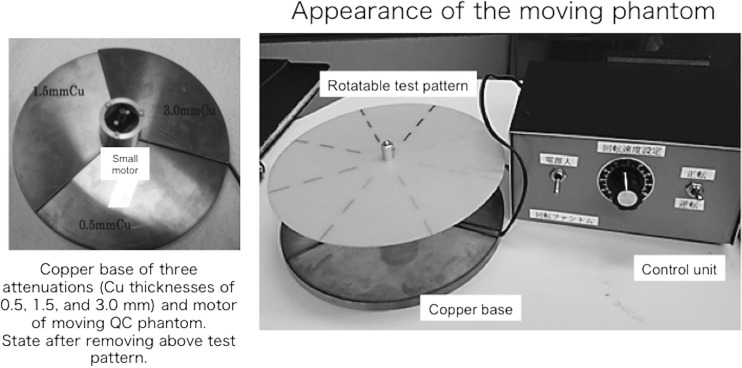
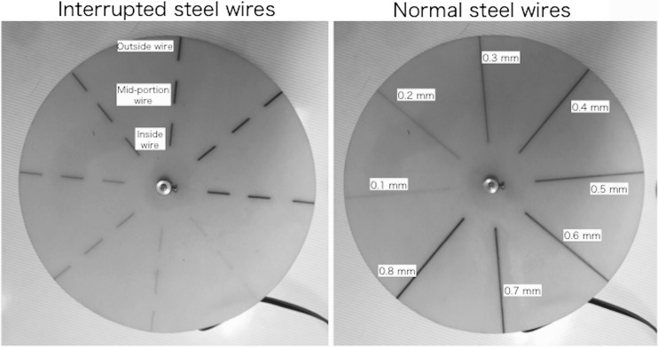
Figure 1 shows the new rotatable QC phantom, which includes a control unit for evaluating the imaging performance of moving objects. The new phantom consists of three thicknesses of copper (Cu) base (the Cu base itself does not rotate), a rotatable test pattern (composed of piano wires of various diameters), and the control unit. To evaluate the wide dynamic range of FPD images, we used three Cu attenuation thicknesses, according to our previous study: low attenuation, 0.5 mm; intermediate attenuation, 1.5 mm; and high attenuation, 3.0 mm [13]. The Cu base had the three attenuations at equal 120° intervals (Fig. 1). The weights and diameters of the Cu base were approximately 0.36 kg and 14 cm, respectively. A thin rotatable test pattern (diameter 14 cm, made from epoxy resin) was placed on top of a small synchronous motor (height 3.7 cm; diameter 1.5 cm) and the Cu base. The motor that rotated the pattern was powered from a control unit using a dry-cell battery (1.5 V). The rotation speed could be manually selected using the control unit (e.g., for speeds of 15 or 30 rpm; it could also be arbitrarily changed). The rotatable test pattern consisted of piano (steel) wires of various diameters (0.1–0.8 mm) spaced at 45° intervals (Fig. 2). We selected two test patterns with either normal steel wires or interrupted steel wires of various diameters (Fig. 2). The weight of the thin test patterns (produced by wires and epoxy resin) was approximately 0.02 kg. There was almost no X-ray attenuation of the patterns except the steel wires (Fig. 2). Then, the moving QC phantom was used to evaluate the spatial resolution and dynamic range of the moving structures, including image retention (and/or motion blur).
Fig. 1.
The appearance of our moving QC phantom for evaluating FPD imaging performance. A Cu base of three attenuations (Cu thicknesses of 0.5, 1.5, and 3.0 mm) and a motor for moving the QC phantom
Fig. 2.
Rotatable test pattern of our moving QC phantom. Piano (steel) wires of various diameters (0.1–0.8 mm). Wires are fixed by an epoxy resin. Two types of rotatable test pattern of our moving QC phantom (interrupted steel wires and normal steel wires).
Preliminary Evaluation of the Moving Phantom
We performed an initial check of the new phantom using a digital cineangiography unit with the FPD (Celeve-i-INFX-8000, Toshiba, Japan). Pulsed fluoroscopy and digital cineradiography were performed at 7.5 pulses/s and 15 frames/s using an 8-in. FPD and the new phantom. The distance from the X-ray focus to the FPD was 90 cm; the phantom was placed on the catheter table. The spatial resolution and dynamic range of the FPD image were visually evaluated using the phantom during the course of approximately 6 weeks. Visual evaluations of images (cineradiography and fluoroscopy) on X-ray display monitors were performed according to mutual agreement between two specialists (radiologic technologists). A display monitor (18.1 in., liquid crystal display; number of pixels = 1280 × 1024) was used and no special processing of the images was undertaken (i.e., we applied routine image processing only).
Results
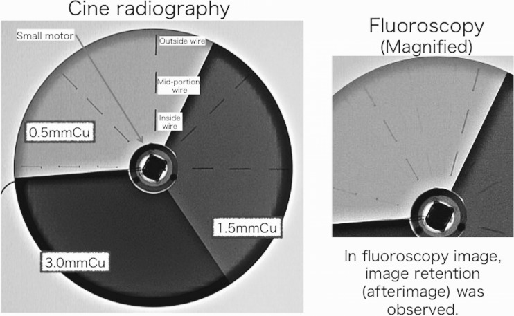
Examples for cineradiography (tube voltage, 70 kV) images of the moving phantom (rotation speed, 30 rpm) with interrupted steel wires taken using the FPD system are shown in Fig. 3. When the rotation speed was 30 rpm, the moving speed of the outside wires became 200 mm/s (and that of the inside wires became 80 mm/s).
Fig. 3.
X-ray images (cineradiography and fluoroscopy) of our moving QC phantom for evaluating FPD image performance
Similarly, Fig. 3 shows fluoroscopy images of the phantom with image retention (after image). Thus, our phantom can evaluate after images (or residual images) for FPD.
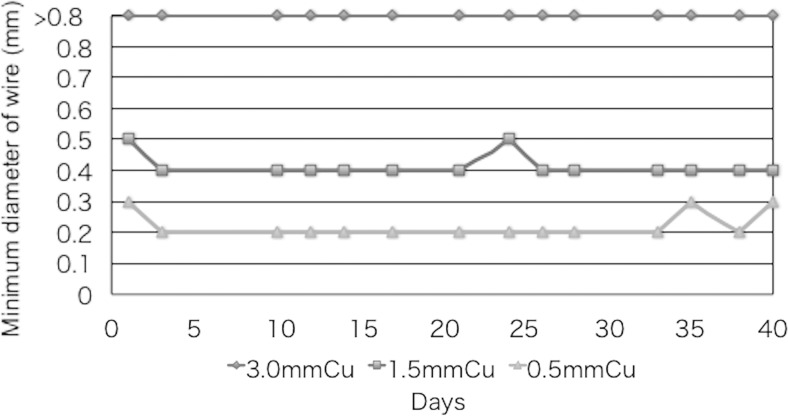
Figure 4 shows the results of the fluoroscopy visual evaluation of the spatial resolution of X-ray images of the phantom at outside wires (in 200 mm/s, 30 rpm) using the three Cu attenuations (Cu thicknesses of 0.5, 1.5, and 3.0 mm) over the course of 6 weeks. Note that the spatial resolution in the thin attenuation setting (0.5 mm Cu) was higher than that in the 3.0 mm Cu.
Fig. 4.
Spatial resolution of X-ray images (fluoroscopy) using the FPD system at outside wires of the moving phantom for three copper attenuations (Cu thicknesses of 0.5, 1.5, and 3.0 mm). QC data were collected two or three times a week
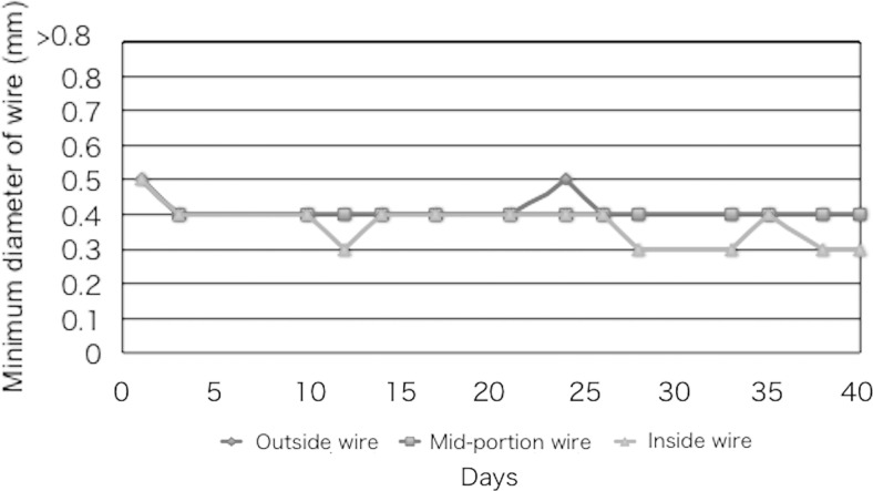
Figure 5 shows the visual evaluation of the spatial resolution for the phantom at the inside wires (80 mm/s), mid-portion wires (140 mm/s), and outside wires (200 mm/s) at 1.5-mm thickness. Note that the inside wires tended to have better spatial resolutions than the outside wires.
Fig. 5.
Spatial resolution of X-ray images (fluoroscopy) using the FPD system at an intermediate attenuation (Cu of 1.5 mm) at inside wires (80 mm/s), mid-portion wires (140 mm/s), and outside wires (200 mm/s)
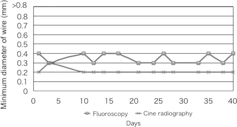
Figure 6 shows the results of the visual evaluation (fluoroscopy and cineradiography) of the spatial resolution for X-ray images of the phantom at the outside wires (in 200 mm/s, 30 rpm) using Cu of 1.5 mm thickness. The fluoroscopic images showed poorer spatial resolution than the cineradiographic images.
Fig. 6.
Comparison of spatial resolution between fluoroscopy and cineradiography at outside wires (200 mm/s, 30 rpm) in Cu of 1.5-mm thickness
Discussion
Wagner et al. reported how easy it is to increase the radiation skin dose by deviating slightly from standard methods of radiation dose management. In their example, a difference of 8 Gy between standard and non-standard methods was observed [11]. Therefore, the QC of X-ray systems is very important [14–19].
QC of FPD imaging performance (e.g., angiography systems) is necessary not only for stationary objects but also for moving objects. The very few rotatable phantoms that exist are designed for image intensifiers (IIs) and thus are not suitable for evaluating the performance of FPDs in imaging moving objects, which have a wide dynamic range [14]. Furthermore, these phantoms are expensive (with costs in excess of US$2,000); so, their use is uncommon.
We introduced a new moving phantom with a rotatable test pattern for evaluating the visualization of moving objects, such as guide wires, in FPD X-ray fluoroscopy systems. Our phantom performed well, because it applies three different thicknesses of copper (low, intermediate, and high attenuation), in contrast to previous phantoms that only use one attenuation. The use of only one attenuation (e.g., only 1.5-mm-thick Cu), such as the previous phantom for IIs, hampers assessment over a wide dynamic range.
The speed of the outside wire in our phantom was approximately 200 mm/s when using 30 rpm. For comparison, the maximum moving speed of coronary arteries has been reported to be 200 mm/s [12]. In our phantom, when the outside wire speed was 200 mm/s, an inside wire speed of 80 mm/s could be obtained. Thus, in the single test pattern used, we could evaluate the performance of FPD in imaging moving wires of both high and low speeds. In addition, visual evaluation is easier with interrupted steel wires than with normal wires, which in the present study was done by evaluating the discrimination of a portion of the inside (80 mm/s), mid-portion (140 mm/s), and outside wires (200 mm/s). Furthermore, our phantom was able to evaluate image retention (afterimage) caused by recursive image filtering for noise reduction in moving images.
Our phantom is inexpensive to make, with an approximate total cost of US$100, compared with previous moving phantoms. Therefore, we expect it to become widely used in the QC of the performance of FPD in imaging moving objects. However, we have yet to ascertain whether we will market our phantom.
In initial tests, our system was reliable for this purpose, and no abnormal data were obtained. At the same time, the QC of an FPD system should also require the monitoring of the X-ray output (or dose), for optimization of image quality and radiation dose.
Our study had several limitations. Because it was a preliminary study, concerned with the development of a new rotatable QC phantom for the evaluation of moving images in a FPD system, further investigation of our phantom, including statistical analysis of the data, is necessary.
Conclusion
Until now, simple rotatable QC phantoms have not been available for the easy evaluation of the performance (spatial resolution and dynamic range) of FPD in imaging moving objects. We developed a QC phantom for this purpose. It consists of three thicknesses of copper and a rotatable test pattern of piano wires of various diameters. Initial tests confirmed its stable performance.
The main focus of this paper was the manufacture of a rotatable QC phantom for the evaluation of the performance of FPDs with respect to imaging moving objects. Although we did not analyze the phantom image data statistically, we consider our novel phantom to be feasible for use in the QC of FPDs when imaging moving objects.
We believe that our phantom is suitable for evaluating the performance of FPD in imaging moving objects and will be very useful for the QC of this process, because it easily facilitates the visual evaluation of image quality (spatial resolution and dynamic range).
Acknowledgments
This study was supported in part by a Grant-in-Aid for Scientific Research (No. 26460716) from the Japan Society for the Promotion of Science. We thank Goro Yokouchi, Mitaya Manufacturing Co., Ltd., Japan, for his invaluable assistance.
References
- 1.Fazel R, Gerber TC, Balter S, Brenner DJ, Carr JJ, Cerqueira MD, Chen J, Einstein AJ, Krumholz HM, Mahesh M, McCollough CH, Min JK, Morin RL, Nallamothu BK, Nasir K, Redberg RF, Shaw LJ, American Heart Association Council on Quality of Care and Outcomes Research, Council on Clinical Cardiology, and Council on Cardiovascular Radiology and Intervention Approaches to enhancing radiation safety in cardiovascular imaging: a scientific statement from the American Heart Association. Circulation. 2014;130(19):1730–1748. doi: 10.1161/CIR.0000000000000048. [DOI] [PubMed] [Google Scholar]
- 2.Chida K, Inaba Y, Saito H, Ishibashi T, Takahashi S, Kohzuki M, Zuguchi M. Radiation dose of interventional radiology system using a flat-panel detector. Am J Roentgenol. 2009;193:1680–1685. doi: 10.2214/AJR.09.2747. [DOI] [PubMed] [Google Scholar]
- 3.Kato M, Chida K, Sato T, Oosaka H, Tosa T, Munehisa M, Kadowaki K. The necessity of follow-up for radiation skin injuries in patients after percutaneous coronary interventions: radiation skin injuries will often be overlooked clinically. Acta Radiol. 2012;53(9):1040–1044. doi: 10.1258/ar.2012.120192. [DOI] [PubMed] [Google Scholar]
- 4.Chida K, Kaga Y, Haga Y, Kataoka N, Kumasaka E, Meguro T, et al. Occupational dose in interventional radiology procedures. Am J Roentgenol. 2013;200(1):138–141. doi: 10.2214/AJR.11.8455. [DOI] [PubMed] [Google Scholar]
- 5.Chida K, Kagaya Y, Saito H, Takai Y, Takahashi S, Yamada S, et al. Total entrance skin dose: an effective indicator of maximum radiation dose to the skin during percutaneous coronary intervention. Am J Roentgenol. 2007;189:W224–W227. doi: 10.2214/AJR.07.2422. [DOI] [PubMed] [Google Scholar]
- 6.Koenig TR, Mettler FA, Wagner LK. Skin injuries from fluoroscopically guided procedures: part 2, review of 73 cases and recommendations for minimizing dose delivered to patient. Am J Roentgenol. 2001;177:13–20. doi: 10.2214/ajr.177.1.1770013. [DOI] [PubMed] [Google Scholar]
- 7.Balter S, Miller DL. Fluoroscopically guided interventional procedures: a review of radiation effects on patients’ skin and hair. Am J Roentgenol. 2014;202(4):W335–W342. doi: 10.2214/AJR.13.12029. [DOI] [PubMed] [Google Scholar]
- 8.Chida K, Ohno T, Kakizaki S, Takegawa M, Yuuki H, Nakada M, Takahashi S, Zuguchi M. Radiation dose to the pediatric cardiac catheterization and intervention patient. Am J Roentgenol. 2010;195:1175–1179. doi: 10.2214/AJR.10.4466. [DOI] [PubMed] [Google Scholar]
- 9.Chida K, Saito H, Otani H, Kohzuki M, Takahashi S, Yamada S, et al. Relationship between fluoroscopic time, dose–area product, body weight, and maximum radiation skin dose in cardiac interventional procedures. Am J Roentgenol. 2006;186:774–778. doi: 10.2214/AJR.04.1653. [DOI] [PubMed] [Google Scholar]
- 10.Tsapaki V, Ahmed NA, AlSuwaidi JS, et al. Radiation exposure to patients during interventional procedures in 20 countries: initial IAEA project results. Am J Roentgenol. 2009;193:559–569. doi: 10.2214/AJR.08.2115. [DOI] [PubMed] [Google Scholar]
- 11.Wagner LK, Archer BR, Cohen AM. Management of patient skin dose in fluoroscopically guided interventional procedures. J Vasc Interv Radiol. 2000;11:25–33. doi: 10.1016/S1051-0443(07)61274-3. [DOI] [PubMed] [Google Scholar]
- 12.Balter S. A new tool for benchmarking cardiovascular fluoroscopes. Radiat Prot Dosim. 2001;94(1–2):161–166. doi: 10.1093/oxfordjournals.rpd.a006464. [DOI] [PubMed] [Google Scholar]
- 13.Chida K, Kaga Y, Haga Y, Takeda K, Zuguchi M. Quality control phantom for flat panel detector X-ray systems. Health Phys. 2013;104(1):97–101. doi: 10.1097/HP.0b013e3182659c72. [DOI] [PubMed] [Google Scholar]
- 14.Halpern EJ, Esser PD, Nickoloff EL, Alderson PO. A quality-control phantom for digitization of radiographs. J Digit Imaging. 1990;3(1):42–48. doi: 10.1007/BF03168110. [DOI] [PubMed] [Google Scholar]
- 15.Chida K, Inaba Y, Masuyama H, Yanagawa I, Mori I, Saito H, Maruoka S, Zuguchi M. Evaluating the performance of a MOSFET dosimeter at diagnostic X-ray energies for interventional radiology. Radiol Phys Technol. 2009;2(1):58–61. doi: 10.1007/s12194-008-0044-z. [DOI] [PubMed] [Google Scholar]
- 16.Chida K, Sai M, Saito H, Takase K, Zuguchi M, Sasaki M, Sato T. Relationship between the pixel value in digital subtraction angiography and iodine concentration: study in high iodine concentration with original phantom. Tohoku J Exp Med. 2000;190(3):169–176. doi: 10.1620/tjem.190.169. [DOI] [PubMed] [Google Scholar]
- 17.Nakamura M, Chida K, Zuguchi M. Red emission phosphor for real-time skin dosimeter for fluoroscopy and interventional radiology. Med Phys. 2014;41(10):101913. doi: 10.1118/1.4893534. [DOI] [PubMed] [Google Scholar]
- 18.Inaba Y, Chida K, Kobayashi R, Haga Y, Zuguchi M. Radiation dose of cardiac IVR x-ray systems: a comparison of present and past. Acta Cardiol. 2015;70(3):299–306. doi: 10.1080/ac.70.3.3080634. [DOI] [PubMed] [Google Scholar]
- 19.Nakamura M, Chida K, Zuguchi M. Novel dosimeter using a nontoxic phosphor for real-time monitoring of patient radiation dose exposure in interventional radiology. Am J Roentgenol. 2015;205(2):W202–W206. doi: 10.2214/AJR.14.13925. [DOI] [PubMed] [Google Scholar]


