

Abstract
Autologous plasma clots with longitudinally aligned fibrin fibers could serve as a scaffold for longitudinal axonal regrowth in cases of traumatic peripheral nerve injuries. Three different techniques for assembling longitudinally oriented fibrin fibers during the fibrin polymerization process were investigated as follows: fiber alignment was induced by the application of either a magnetic field or—as a novel approach—electric field or by the induction of orientated flow. Fiber alignment was characterized by scanning electron microscopy analysis followed by image processing using fast Fourier transformation (FFT). Besides FFT output images, area xmin to xmax, as well as full width at half maximum (FWHM) of the FFT graph plot peaks, was calculated to determine the relative degree of fiber alignment. In addition, fluorescently labeled human fibrinogen and mesenchymal stem cells (MSCs) were used to visualize fibrin and cell orientation in aligned and nonaligned plasma clots. Varying degrees of fiber alignment were achieved by the three different methods, with the electric field application producing the highest degree of fiber alignment. The embedded MSCs showed a longitudinal orientation in the electric field-aligned plasma clots. The key feature of this study is the ability to produce autologous plasma clots with aligned fibrin fibers using physical techniques. This orientated internal structure of an autologous biomaterial is promising for distinct therapeutic applications, such as a guiding structure for cell migration and growth dynamics.
Introduction
Although surgical techniques for peripheral nerve repair have been improved over the last several decades, the clinical results are not consistently successful. The transplantation of an autogenous nerve graft, taken primarily from the sural nerve of the injured patient, is considered the “gold standard” for bridging peripheral nerve gaps.1 However, this technique is associated with several disadvantages, including donor-site morbidity, the need for an additional surgical procedure, painful scar formation, sensory loss, and abnormal sensitivity.2,3 Furthermore, the overall success rate is only ∼50%.4,5 Attempts to avoid these problems and to improve outcomes have been made with artificial implants, such as nerve conduits.6,7 They are designed as hollow tubes, in which the nerve ends are inserted.8,9 Conduit biomaterials have to fulfill general requirements as biocompatibility, biodegradability, and porosity. There are numerous material design strategies to generate successful nerve conduits, such as the development of biopolymers and synthetic polymers.10 However, due to their tubular construction, hollow nerve conduits provide limited support for axonal regrowth.11,12 Therefore, an incorporation of a soft interior matrix with a longitudinally orientated texture could be helpful for effectively promoting the longitudinal axonal regrowth. Different filler biomaterials, such as keratin hydrogels, laminin, fibronectin, or fibrin, have been used.10 Various microfabrication methods have been developed to generate matrices, which assist the alignment of axonal outgrowth, such as electrospinning13 and microfluidic spinning14 of polymers, mechanically induced fiber alignment of collagen/alginate15,16 or alignment within a strong magnetic field.17,18 These strategies led to various structural intraluminal guidance cues, which may act as a replacement for the randomly formed fibrin networks that emerge after physiological plasma clotting.4
Notably, an autologous plasma clot matrix would itself be a promising biomaterial for longitudinal axonal regrowth if the randomly orientated fibrin network could be aligned unidirectionally. Such a plasma clot would possess a microporous three-dimensional structure and excellent biocompatibility and would allow the diffusion of nutritional and regulatory factors.19–22 Another advantage of an autologous plasma clot is that it does not require allogeneic or xenogeneic factors during clot preparation, in contrast to commercially available fibrin sealant systems. The feasibility of such a plasma clot system under clinical conditions has been demonstrated earlier by our group.23
Therefore, the aims of this study were to induce the alignment of fibrin fibers during the clotting process using different methods and to analyze the extent of fiber alignment.
Materials and Methods
Plasma clot preparation
Platelet-free plasma was prepared by centrifugation of citrated blood (S-Monovette; Sarstedt) at 2000 g (45 min, room temperature). After centrifugation, the plasma was aspirated and used for the experiments.
Plasma clots were generated by mixing plasma with the same volume of RPMI 1640 (Life Technologies GmbH) and adding CaCl2 (Sigma Aldrich) to a final concentration of 5% of the plasma volume. The added CaCl2 solution was 10% in water. Both chambers of a two-chamber slide (Nunc) were filled with 1 mL of the prepared mixture and left for 60 min at room temperature to allow polymerization under the different fibrin fiber alignment conditions.
To analyze the fiber orientation by confocal laser scanning microscopy, the plasma mixtures were supplemented with prelabeled human fibrinogen conjugated with Alexa Fluor 594 (Molecular Probes). Therefore, 10 μL of the fluorescent fibrinogen was added to 1 mL plasma mixture before the polymerization process was started. Partly, human mesenchymal stem cells (MSCs) obtained from Lonza Walkersville, Inc. were added to the plasma clotting mixture before the polymerization process was started (4000 cells/mL RPMI medium) and for these experiments, cell-loaded plasma clots were subsequently cultured for 1 week after the fibrin fiber alignment procedures.
The viability and morphology of embedded MSCs were analyzed using calcein-acetoxymethylester (calcein-AM; Calbiochem) fluorescence staining. The clots were washed twice with RPMI 1640 and incubated with calcein-AM (1 μM) at 37°C for 30 min under cell culture conditions. Subsequently, the clots were washed again with RPMI and analyzed by confocal laser scanning microscopy (Zeiss LSM 700).
Alignment of fibrin fibers by magnetic field
Two magnet stacks consisting of seven cuboids (NdFeB NeoDelta Magnet: 20 × 10 × 5 mm; IBS Magnet) were used for experiments (Fig. 1). The magnetic field strength was 0.25 T in the mid of the chamber and 1.2 T at the poles. Both magnet stacks were fixed on a Teflon tray to leave exactly enough space for the two-chamber slide, which was finally sandwiched between the magnets (Fig. 1). For fibrin fiber alignment, the chamber adjacent to the magnet stacks was filled with the plasma mixture.
FIG. 1.
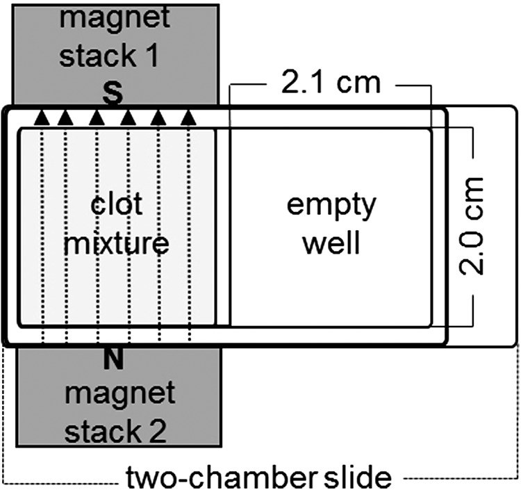
Experimental setup for the magnetic alignment of plasma fibrin fibers in one chamber of a two-chamber slide (surface area: 4.2 cm2) with two adjacent magnet stacks (the second chamber of the chamber slide remained empty due to the size of the magnet stacks). The direction of the magnetic field (dotted lines), which connects the south pole (S) of magnet stack 1 and the north pole (N) of magnet stack 2, is marked by arrows.
Alignment of fibrin fibers by electric field
A specific experimental setup was developed to apply an electric field during clot polymerization. Initially, copper strips (4 mm in width ×0.1 mm in height) were fixed at both longitudinal sides of a chamber slide, and each was connected with a copper strip (8 mm in width ×0.1 mm in height) at right angles. The longitudinal copper strips were then insulated. The wider copper strips were connected to a high-voltage power supply (Spellman High Voltage Electronics Corporation) (Fig. 2). An electric field of 15 kV was applied using electrodes integrated into a special high-voltage protection plastic box (Fig. 2). The power supply was switched on immediately after filling the chamber with the plasma mixture.
FIG. 2.
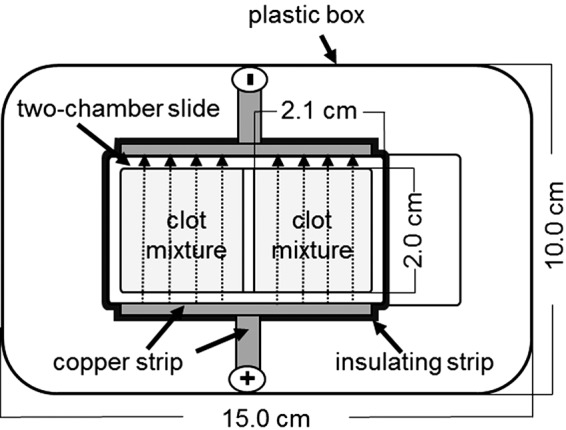
Experimental setup for the electrical alignment of plasma fibrin fibers. The direction of the electric field (dotted lines) extending from the positive charge to the negative charge is marked by arrows. Both wells of the chamber slide were filled with the plasma mixture.
Fiber alignment by flow induction
For the so-called flow experiments, a horizontal shaker (IKA HS 500; IKA) and a rocking shaker (Mini-Rocker Shaker MR-1; Biosan) were used (Fig. 3). Plasma mixtures were added to two-chamber slides that were fixed on each shaker. The shaking frequency of the horizontal shaker was 15 rpm (Fig. 3B). The Mini-Rocker Shaker had a fixed tilt angle of 7° and a motion frequency of 7.5 oscillations/min (Fig. 3A). Both shakers induced a gentle back and forth motion (flow) of the plasma mixture in a given direction.
FIG. 3.
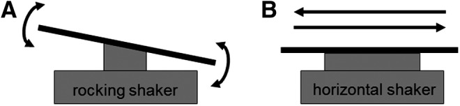
Alignment of plasma fibrin fibers under flow conditions. (A) The movement of the rocking shaker (7° tilt angle) was upward and downward, as shown by arrows. (B) The movement of the horizontal shaker was from left to right and reverse, as shown by arrows.
Clot preparation for scanning electron microscopy
The morphology of the plasma clots was examined using a DSM 962 scanning electron microscope (Zeiss Oberkochen). The clots were measured between 3 and 5 mm in length and 3 mm in height. Clots were washed in phosphate-buffered saline (PBS), fixed with 4% glutaraldehyde in PBS for 24 h at 4°C, and washed in distilled water. Subsequently, the clots were dehydrated in a graded series of ethanol (30%, 50%, 70%, 90%, and 96% for 15 min each), followed by infiltration with pentyl acetate (Sigma Aldrich) for 15 min. After critical point drying with CO2 (K850; Quorum Technologies), the specimens were mounted on scanning electron microscopy (SEM) carriers and sputter coated with a 12.5 nm gold–palladium layer (K500X; EMITECH). At areas where the clot skin was ripped due to the preparation procedure, images from interior fibrin fibers at near surface sites were taken. Areas that were representative for the entire clots were examined, and SEM micrographs were taken at a magnification of 3000×.
Fast Fourier transformation analysis of fiber alignment
Fast Fourier transformation (FFT) analysis of the SEM micrographs was performed to evaluate the plasma clot fiber alignment. ImageJ 1.44 software (NIH) with oval profile plugin (William O'Connel) was used for image processing and FFT measurement. For analysis, the SEM images were converted to 8-bit grayscale TIF files and cropped to 2048 × 2048 pixels. To reduce background noise and edge effects, the background was subtracted, and the contrast was enhanced. Then, the image was filtered with a median filter (radius: two pixels) (Fig. 4A). Subsequently, the image was processed with the FFT tool (ImageJ) to produce a grayscale FFT output image of the frequency information (Fig. 4B). The grayscale pixels were distributed in a pattern that reflected the degree of the fibrin fiber alignment in the original SEM image. The FFT output image was rotated 90° to compensate for the 90° rotation during FFT processing, and an elliptical selection was set (Fig. 4C). The ImageJ oval profile plugin was used to sum the frequency information along a radius from the center to the edges of the elliptical selection (Fig. 4D). A graphical plot showed the FFT frequency distribution determined by conducting a radial summation of the intensities for each degree between 1° and 360°. The average intensities and corresponding angles were transferred to an Excel spreadsheet. All FFT data were normalized to a baseline value of 0 and plotted as a function of the corresponding angle. The fibrin fiber orientation in the original SEM image was reflected by the height and the shape of the peak in the graphical plot.
FIG. 4.

Fast Fourier Transformation (FFT) analysis sequence. (A) Original scanning electron microscopy (SEM) image after image processing. (B) FFT output image of the frequency information. (C) 90° rotation of FFT output image and elliptical selection. (D) Hotspot of FFT (analysis mode: radial sums; number of points: 200). Color images available online at www.liebertpub.com/tec
In addition, the area (xmin to xmax) and full width at half maximum (FWHM) of the peaks were calculated to determine the relative degree of fiber alignment.
Statistical analyses
Statistical analyses were performed with OpenStat software (Industrial Technology Department, Iowa State University). The data are expressed as the mean ± standard deviation (n = 3, independent experiments). FWHM and peak areas were analyzed using one-way analysis of variance (ANOVA) followed by Tukey's multiple comparison test with a significance level of p < 0.05.
Results
To address the need for a biomaterial that is able to assist and guide nerve growth and that is as biocompatible as possible, we studied a plasma clot matrix, in which the randomly orientated fibrin fiber network was aligned by applying different experimental conditions during the polymerization process. Calcium chloride was used to trigger the clotting of a mixture of a cell culture medium and platelet-free citrated blood plasma within an electric or magnetic field or under unidirectional movement of the clotting fluid and compared to a clotting process in the absence of experimental manipulation (control).
Alterations in fibrin fiber alignment were not observed at different sites of an individual plasma clot. Under the different polymerization conditions, plasma clots with varying degrees of fibrin fiber alignment were generated as shown in Figure 5–7. In contrast to the pattern of randomly orientated fibers observed within the control plasma clot (Fig. 5A), aligned fiber networks were observed in the manipulated plasma clots.
FIG. 5.

(A) Representative scanning electron micrograph of a nonaligned plasma clot (control). (B) FFT output image of (A) and normalized intensity plotted against the corresponding angle. (C) SEM image of fibrin fibers aligned in a magnetic field. The direction of the magnetic field is marked with a white arrow. (D) FFT output image of (C) and the resulting FFT plot.
FIG. 6.

(A) Representative scanning electron micrographs of fibrin fibers aligned in an electric field. The white arrow indicates the aligned direction of the fibers. (B) FFT output image of (A) and normalized intensity plotted against corresponding angle.
FIG. 7.

Representative scanning electron micrographs of fibrin networks polymerized under flow on a rocking shaker (A) or a horizontal shaker (C). The flow direction is marked with a white arrow. (B) FFT output image of (A) and the resulting FFT plot. (D) FFT output image of (C) and the resulting FFT plot.
The degree of unidirectional fiber orientation was then quantitatively analyzed by digital image processing using FFT analysis. In this analysis, the typical randomly branched fiber network of control clots with relatively uniform fiber diameters resulted in a symmetrical circular profile (Fig. 5A) of the FFT output image, indicating that the image pixel intensity was uniform in all directions (Fig. 5B insert). The corresponding FFT graph plot of the control clot appeared as a line with many small frequency peaks, demonstrating that there was no pattern alignment within the image (Fig. 5B).
In contrast, the presence of a directed magnetic field during the clotting process produced a more parallel fiber orientation along the magnetic field lines (Fig. 5C), which is reflected by the elliptical profile of the FFT output image (Fig. 5D insert) and corresponding FFT graph plot that contains a peak representing a directional distribution of image intensity signals (Fig. 5D).
Figure 6A shows that the exposure to an electric field also had a strong directional influence on fibrin fiber organization during clot polymerization. FFT analysis resulted in a small elongated ellipse representing the FFT output image (Fig. 6B insert), and the FFT graph plot showed a symmetrical peak at 90° (Fig. 6B).
The presence of unidirectional flow during the clotting process also affected clot structure. Under static conditions, fibrin fibers formed a homogeneous randomly distributed network (Fig. 5A), and while under flow conditions, fibers were orientated parallel to the flow direction (Fig. 7A, C). Especially after flow induction using the rocking shaker, we observed the formation of large fiber bundles that were interconnected by thin fibers. FFT analyses showed an elliptical profile, indicating a single general fiber direction (Fig. 7B, D). The FFT graph generated a peak at 90° for flow experiments on a rocking shaker (Fig. 7B) and a peak at ∼100° on the horizontal shaker (Fig. 7D).
The different fiber alignment procedures were compared by analyzing the peak width (FWHM) in the FFT plot, as shown in Figure 8. This peak parameter was similar for three of the alignment procedures (horizontal shaker, 70.9° ±6.3°; magnetic field, 71.0° ±5.5°; rocker shaker, 68.4° ±6.3°), but significantly lower after the application of the electric field (58.04° ±5.86°), indicating a higher degree of orientation of the generated fibers. The quantitation of the peak area (xmin to xmax) yielded similar results (data not shown).
FIG. 8.

Full width at half maximum (FWHM) of the FFT plot peaks. Values are presented as mean ± standard deviation. Statistical analysis was performed using one-way analysis of variance (ANOVA), followed by Tukey's test; significance was set at p ≤ 0.05. Three independent experiments were performed for each alignment procedure.
To permit the microscopic visualization of fiber alignment within the plasma clot, fluorescently labeled human fibrinogen (1%, Alexa Fluor 594-conjugated) was added to the plasma fluid before the clotting process. Confocal laser scanning microscopy was performed after clot polymerization. Figure 9 demonstrates the random fibrin network of control clots (Fig. 9A), in contrast to the highly aligned fibers obtained after electric field exposure (Fig. 9D).
FIG. 9.

Representative confocal laser-scanning micrographs of a nonaligned plasma clot (control) (A) and a clot aligned in an electric field (D) (magnification: 63×). Before polymerization, clots were labeled with Alexa Fluor 594-conjugated human fibrinogen. Mesenchymal stem cells (MSCs) were embedded in nonaligned (B) and aligned plasma clots (E), cultured for 1 week under conventional culture conditions and subsequently stained with calcein-AM. Green fluorescence represents viable MSCs. FFT plot of cell orientation in plasma clots with nonaligned fibers (C). FFT plot of cell orientation in plasma clots with aligned fibers (F). Color images available online at www.liebertpub.com/tec
Finally, human MSCs were added to the plasma fluid (also containing 1% labeled fibrinogen) before polymerization, and clots were generated either under static (control) polymerization conditions (Fig. 9B) or under the influence of the electric field (Fig. 9E). The electric field did not affect cell viability. In general, MSCs are viable within this plasma clot and are even able to proliferate within such a matrix.24 The cell orientation in plasma clots with nonaligned fibers clearly remained random (Fig. 9B); in contrast, MSCs exhibited a longitudinal orientation along the aligned fibrin fibers (Fig. 9E). The alignment of the embedded MSCs was analyzed by FFT, similar as it was performed for fibrin fibers using here only the green fluorescence images, which resemble the living MSCs embedded in the plasma clot. As it is shown after electric field fiber alignment, the MSCs are quantitatively orientated in the direction of the fibrin fibers (Fig. 9F), in contrast to cells adherent to nonaligned fibers (Fig. 9C). FFT analysis confirmed the unidirectional orientation of the MSCs along the fibrin fibers showing a small elongated ellipse representing the FFT output image (Fig. 9F insert) and a symmetrical peak at 90° of the respective FFT graph plot (Fig. 9F) in contrast to MSCs within the nonaligned fibrin matrix (Fig. 9C). Quantitatively, the alignment of MSCs resulted in a peak width of 54 (FWHM) in the FFT plot that was in the range of fibrin fiber alignment (Fig. 7).
Discussion
In this study, we have shown that it is possible to obtain fibrin fiber alignment within a plasma clot matrix using exclusively physical methods. Earlier approaches have used commercially available fibrin glue as filler for nerve conduits to enhance nerve regeneration; conduits loaded with a fibrin matrix did not inhibit regeneration, in contrast to the results obtained with alginate gels.25,26 Furthermore, the use of a fibrin conduit in the repair of nerve gaps improved nerve regeneration distance and Schwann cell intrusion in a rodent sciatic nerve injury model.27 Choi et al. reported that a vein graft filled with an autologous fibrin glue produced superior axonal regeneration compared with grafts filled with commercial fibrin glue in a rabbit model.28 However, both studies involved an extensive fibrinogen harvesting method consisting of ethanol precipitation, the subsequent isolation of fibrinogen-free plasma and, finally, the induction of fibrin fiber formation through the addition of enriched thrombin.27,28 The approach presented in our study seems to have several methodological advantages for use in a fibrin-containing conduit, namely, a less cumbersome fibrin clot preparation technique and an orientation of the fibrin fibers or bundles that is no more time consuming than the clotting process itself.
In contrast to a variety of artificial and synthetic implants, the plasma clot functions not just as a passive cell-transferring matrix but also as a source of many growth factors.21,29 It is well known that the fibrin molecules within the plasma clot serve as storage and release system for a variety of bioactive factors, including growth factors.19,20 In addition, the biological half-life of bioactive molecules may be prolonged by binding to the fibrin matrix.20 The conclusion that a fibrin matrix within a nerve conduit generally favors axonal outgrowth and cannot grow per se. However, inside hollow conduits, the wound healing process results in the formation of a fibrin matrix in the lumen and across short lengths.4,30 This physiological response provides a scaffold for the immigration of cells from both nerve stumps.31 The previous alignment of an intraluminal fibrin matrix may facilitate these regenerative processes.
The ideal pore size in a nerve regeneration matrix has yet to be clinically determined, and the fiber size in plasma clots is easily controlled by altering the fibrinogen or calcium concentrations.21,24 Furthermore, bioactive molecules, such as nerve growth factors, and regeneration-supporting cells, such as MSCs, can be added before clot gelation to enhance regeneration processes.32 However, there are a few drawbacks to the use of plasma clots that consist of completely autologous material to avoid allo- or xenograft-induced immune reactions or the transfection of pathogens. In contrast to commercially available fibrin matrices or sealants, in which the matrix strength may be adjusted using different concentrations of fibrinogen and thrombin,33 autologous plasma clots have a more heterogeneous microstructure.23 In addition, there is a significant genetic contribution to variance in coagulation and fibrinolytic factors, which may influence the individual clot structure and, thus, must be considered.34
Although the alignment of fibrin fibers was generally achieved by the used methods, lateral crossbridging of fibrin fibers also occurred with different degrees. It has been described that crossfibers disturb the axonal outgrowth in an electrospun PLLA-fiber scaffold.35 Whether fibrin crossbridging fibers will exert similar effects has to be proven, however, it is known from the early work of Cajal36 that regenerating axons are able to take winding pathways.
Different methods for aligning fibrin molecules have been reported. The application of strong magnetic fields (8–20 T) during the polymerization process has produced highly orientated fibrin gels in several different studies.17,18,37,38 In contrast, we demonstrated that fibrin fiber alignment can be achieved at a magnetic field strength as low as 0.25 T, consistent with the results reported by Yamagishi et al. demonstrating fiber alignment at 1 T.18 The fibrin orientation induced by flow has also been analyzed in platelet-poor or platelet-free plasma. Gersh et al. simulated the physiological effects of blood flow on clot organization in vitro.39 These authors showed that fibrin fibers oriented in the flow direction and that alignment increased as the flow rate increased. Campbell et al. flowed plasma over a layer of fibroblasts and observed significant alignment of the fibrin fibers parallel to the flow.40 In our study, the fibrin formed thicker fibers under the flow conditions than under the other two alignment conditions. Although the thick fibers aligned by flow would support rapid plasmin generation, these fibers would also lyse more slowly.40
The alignment of different materials within an electric field was observed in many studies of a variety of different structures, including supramolecular fibers41 and nanotubes.42 However, to the best of our knowledge, the alignment of fibrin orientation has not yet been described. Thus, our observation that exposure to an electric field induced highly orientated fibers is of particular interest. In addition, the viability and proliferation of embedded human MSCs were not affected by electric field exposure, and the cells were orientated in the same direction as the generated fibrin fibers. The combination of an efficient and safe clinical grade matrix with a nerve growth-guiding internal structure appears to be advantageous as nerve conduit filler. Currently, a variety of commercially available synthetic nerve conduits have been approved by regulatory authorities.8
Acknowledgment
This study was supported by a research grant from the German Statutory Accident Insurance (Deutsche Gesetzliche Unfallversicherung, DGUV).
Disclosure Statement
No competing financial interests exist.
References
- 1.Siemionow M., and Brzezicki G. Chapter 8: current techniques and concepts in peripheral nerve repair. Int Rev Neurobiol 87, 141, 2009 [DOI] [PubMed] [Google Scholar]
- 2.Alluin O., Wittmann C., Marqueste T., Chabas J.F., Garcia S., Lavaut M.N., Guinard D., Feron F., and Decherchi P. Functional recovery after peripheral nerve injury and implantation of a collagen guide. Biomaterials 30, 363, 2009 [DOI] [PubMed] [Google Scholar]
- 3.IJpma F.F., Nicolai J.P., and Meek M.F. Sural nerve donor-site morbidity: thirty-four years of follow-up. Ann Plast Surg 57, 391, 2006 [DOI] [PubMed] [Google Scholar]
- 4.Daly W., Yao L., Zeugolis D., Windebank A., and Pandit A. A biomaterials approach to peripheral nerve regeneration: bridging the peripheral nerve gap and enhancing functional recovery. J R Soc Interface 9, 202, 2012 [DOI] [PMC free article] [PubMed] [Google Scholar]
- 5.Madduri S., Papaloizos M., and Gander B. Trophically and topographically functionalized silk fibroin nerve conduits for guided peripheral nerve regeneration. Biomaterials 31, 2323, 2010 [DOI] [PubMed] [Google Scholar]
- 6.Inada Y., Hosoi H., Yamashita A., Morimoto S., Tatsumi H., Notazawa S., Kanemaru S., and Nakamura T. Regeneration of peripheral motor nerve gaps with a polyglycolic acid-collagen tube: technical case report. Neurosurgery 61, E1105, 2007 [DOI] [PubMed] [Google Scholar]
- 7.Carlstedt T. An overture to basic science aspects of nerve injuries. J Hand Surg Eur Vol 36, 726, 2011 [DOI] [PubMed] [Google Scholar]
- 8.Meek M.F., and Coert J.H. US Food and Drug Administration/Conformit Europe-approved absorbable nerve conduits for clinical repair of peripheral and cranial nerves. Ann Plast Surg 60, 110, 2008 [DOI] [PubMed] [Google Scholar]
- 9.de Ruiter G.C., Malessy M.J., Yaszemski M.J., Windebank A.J., and Spinner R.J. Designing ideal conduits for peripheral nerve repair. Neurosurg Focus 26, E5, 2009 [DOI] [PMC free article] [PubMed] [Google Scholar]
- 10.Nectow A.R., Marra K.G., and Kaplan D.L. Biomaterials for the development of peripheral nerve guidance conduits. Tissue Eng Part B Rev 18, 40, 2012 [DOI] [PMC free article] [PubMed] [Google Scholar]
- 11.Yucel D., Kose G.T., and Hasirci V. Tissue engineered, guided nerve tube consisting of aligned neural stem cells and astrocytes. Biomacromolecules 11, 3584, 2010 [DOI] [PubMed] [Google Scholar]
- 12.Pabari A., Yang S.Y., Seifalian A.M., and Mosahebi A. Modern surgical management of peripheral nerve gap. J Plast Reconstr Aesthet Surg 63, 1941, 2010 [DOI] [PubMed] [Google Scholar]
- 13.Tian L., Prabhakaran M.P., and Ramakrishna S. Strategies for regeneration of components of nervous system: scaffolds, cells and biomolecules. Regen Biomater 2, 31, 2015 [DOI] [PMC free article] [PubMed] [Google Scholar]
- 14.Kang E., Choi Y.Y., Chae S.K., Moon J.H., Chang J.Y., Lee S.H. Microfluidic spinning of flat alginate fibers with grooves for cell-aligning scaffolds. Adv Mater 24, 4271, 2012 [DOI] [PubMed] [Google Scholar]
- 15.Chaubaroux C., Perrin-Schmitt F., Senger B., Vidal L., Voegel J.C., Schaaf P., Haikel Y., Boulmedais F., Lavalle P., Hemmerlé J. Cell alignment driven by mechanically induced collagen fiber alignment in collagen/alginate coatings. Tissue Eng Part C Methods 21, 881, 2015 [DOI] [PMC free article] [PubMed] [Google Scholar]
- 16.Zhang S., Liu X., Barreto-Ortiz S.F., Yu Y., Ginn B., DeSantis N., Hutton D.L., Grayson W., Cui F.Z., Korgel B.A., Gerecht S., and Mao H.Q. Creating polymer hydrogel microfibres with internal alignment via electrical and mechanical stretching. Biomaterials 35, 3243, 2014 [DOI] [PMC free article] [PubMed] [Google Scholar]
- 17.Iwasaka M., Takeuchi M., Ueno S., and Tsuda H. Polymerization and dissolution of fibrin under homogeneous magnetic fields. J Appl Phys 83, 6453, 1998 [Google Scholar]
- 18.Yamagishi A., Takeuchi T., Higashi T., and Date M. Magnetic field effect on the polymerization of fibrin fibers. Physica B 164, 222, 1990 [Google Scholar]
- 19.Wong C., Inman E., Spaethe R., and Helgerson S. Fibrin-based biomaterials to deliver human growth factors. Thromb Haemost 89, 573, 2003 [PubMed] [Google Scholar]
- 20.Mosesson M.W. Fibrinogen and fibrin structure and functions. J Thromb Haemost 3, 1894, 2005 [DOI] [PubMed] [Google Scholar]
- 21.Janmey P.A., Winer J.P., and Weisel J.W. Fibrin gels and their clinical and bioengineering applications. J R Soc Interface 6, 1, 2009 [DOI] [PMC free article] [PubMed] [Google Scholar]
- 22.Anitua E., Prado R., and Orive G. Endogenous morphogens and fibrin bioscaffolds for stem cell therapeutics. Trends Biotechnol 31, 364, 2013 [DOI] [PubMed] [Google Scholar]
- 23.Schildhauer T.A., Seybold D., Geßmann J., Muhr G., and Köller M. Fixation of porous calcium phosphate with expanded bone marrow cells using an autologous plasma clot. Mat-wiss u Werkstofftech 38, 1012, 2007 [Google Scholar]
- 24.Gessmann J., Seybold D., Peter E., Schildhauer T.A., and Köller M. Plasma clots gelled by different amounts of calcium for stem cell delivery. Langenbecks Arch Surg 398, 161, 2013 [DOI] [PubMed] [Google Scholar]
- 25.Kalbermatten D.F., Kingham P.J., Mahay D., Mantovani C., Pettersson J., Raffoul W., Balcin H., Pierer G., and Terenghi G. Fibrin matrix for suspension of regenerative cells in an artificial nerve conduit. J Plast Reconstr Aesthet Surg 61, 669, 2008 [DOI] [PubMed] [Google Scholar]
- 26.Mosahebi A., Wiberg M., and Terenghi G. Addition of fibronectin to alginate matrix improves peripheral nerve regeneration in tissue-engineered conduits. Tissue Eng 9, 209, 2003 [DOI] [PubMed] [Google Scholar]
- 27.Kalbermatten D.F., Pettersson J., Kingham P.J., Pierer G., Wiberg M., and Terenghi G. New fibrin conduit for peripheral nerve repair. J Reconstr Microsurg 25, 27, 2009 [DOI] [PubMed] [Google Scholar]
- 28.Choi B.H., Han S.G., Kim S.H., Zhu S.J., Huh J.Y., Jung J.H., Lee S.H., and Kim B.Y. Autologous fibrin glue in peripheral nerve regeneration in vivo. Microsurgery 25, 495, 2005 [DOI] [PubMed] [Google Scholar]
- 29.Catelas I., Dwyer J.F., and Helgerson S. Controlled release of bioactive transforming growth factor beta-1 from fibrin gels in vitro. Tissue Eng Part C Methods 14, 119, 2008 [DOI] [PubMed] [Google Scholar]
- 30.Belkas J.S., Shoichet M.S., and Midha R. Peripheral nerve regeneration through guidance tubes. Neurol Res 26, 151, 2004 [DOI] [PubMed] [Google Scholar]
- 31.Evans G.R. Peripheral nerve injury: a review and approach to tissue engineered constructs. Anat Rec 263, 396, 2001 [DOI] [PubMed] [Google Scholar]
- 32.Seybold D., Schildhauer T.A., Gessmann J., Muhr G., Köller M., and Roetman B. Osteogenic differentiation of human mesenchymal stromal cells is promoted by a leukocytes containing fibrin matrix. Langenbecks Arch Surg 395, 719, 2010 [DOI] [PubMed] [Google Scholar]
- 33.Ho W., Tawil B., Dunn J.C., and Wu B.M. The behavior of human mesenchymal stem cells in 3D fibrin clots: dependence on fibrinogen concentration and clot structure. Tissue Eng 12, 1587, 2006 [DOI] [PubMed] [Google Scholar]
- 34.Deschaseaux F., Sensebe L., and Heymann D. Mechanisms of bone repair and regeneration. Trends Mol Med 15, 417, 2009 [DOI] [PubMed] [Google Scholar]
- 35.Wang H.B., Mullins M.E., Cregg J.M., Hurtado A., Oudega M., Trombley M.T., and Gilbert R.J. Creation of highly aligned electrospun poly-L-lactic acid fibers for nerve regeneration applications. J Neural Eng 6, 016001, 2009 [DOI] [PubMed] [Google Scholar]
- 36.Cajal R.S. Degeneration and Regeneration of the Nervous System, vol. 1. London: Oxford University Press, 1928. [Google Scholar]
- 37.Torbet J., Freyssinet J.M., and Hudry-Clergeon G. Oriented fibrin gels formed by polymerization in strong magnetic fields. Nature 289, 91, 1981 [DOI] [PubMed] [Google Scholar]
- 38.Freyssinet J.M., Torbet J., and Hudry-Clergeon G. Fibrinogen and fibrin in strong magnetic fields. Complementary results and discussion. Biochimie 66, 81, 1984 [DOI] [PubMed] [Google Scholar]
- 39.Gersh K.C., Edmondson K.E., and Weisel J.W. Flow rate and fibrin fiber alignment. J Thromb Haemost 8, 2826, 2010 [DOI] [PMC free article] [PubMed] [Google Scholar]
- 40.Campbell R.A., Aleman M., Gray L.D., Falvo M.R., and Wolberg A.S. Flow profoundly influences fibrin network structure: implications for fibrin formation and clot stability in haemostasis. Thromb Haemost 104, 1281, 2010 [DOI] [PMC free article] [PubMed] [Google Scholar]
- 41.Sardone L., Palermo V., Devaux E., Credgington D., de Loos M., Marletta G., Cacialli F., van Esch J., and Samori P. Electric-field-assisted alignment of supramolecular fibers. Adv Mater 18, 1276, 2006 [Google Scholar]
- 42.Kumar M.S., Lee S.H., Kim T.Y., Kim T.H., Song S.M., Yang J.W., Nahm K.S., and Suh E.-K. DC electric field assisted alignment of carbon nanotubes on metal electrodes. Solid-State Elect 47, 2075, 2003 [Google Scholar]