Abstract
Computer simulations of an implicit-solvent particle-based model are performed to investigate the interactions between small spherical nanoparticles and tensionless lipid bilayers. We found that nanoparticles are either unbound, wrapped by the bilayer, or endocytosed. The degree of wrapping increases with increasing the adhesion strength. The transition adhesion strength between the unbound and partially wrapped states decreases as the nanoparticle diameter is increased. We also observed that the transition adhesion strength between the wrapped states and endocytosis state decreases with increasing the nanoparticle diameter. The partial wrapping of the nanoparticles by the tensionless bilayer is explained by an elastic theory which accounts for the fact that the interaction between the nanoparticle and the bilayer extends beyond the contact region. The theory predicts that for small nanoparticles, the wrapping angle increases continuously with increasing the adhesion strength. However, for relatively large nanoparticles, the wrapping angle exhibits a discontinuity between weakly and strongly wrapped states. The size of the gap in the wrapping angle between the weakly wrapped and strongly wrapped states increases with decreasing the range of nanoparticle-bilayer interaction.
I. INTRODUCTION
Significant advances in nanoscience and nanotechnology during the last two decades have led to an increasing use of nanomaterials in a range of applications including medicine, cosmetics, food, imaging, nanoelectronics, and data storage. A wide variety of nanomaterials, including gold nanoparticles (NPs),1 magnetic NPs,2 quantum dots,3 single-wall carbon nanotubes,4 polymer based nanocapsules,5 and NP conjugates,6 have emerged as promising agents for biosensing,7,8 medical imaging,9 gene therapy,10 and potential treatment of diseases such as cancer.11 Meanwhile, a particularly challenging environmental concern has emerged due to the increasing production of NPs in research laboratories and industry. In particular, there is a growing concern that many types of NPs are discharged into the environment while their potential toxic effect on living organisms remains poorly understood.12 Since the plasma membrane constitutes the point of entry for living cells, a fundamental understanding of how NPs interact with biomembranes is urgently warranted.
Understanding the cellular uptake of NPs is prerequisite to their safe use in many applications, while minimizing their potential health hazards. The main uptake of material by the plasma membrane occurs through the membrane engulfment of the material. Such uptakes are divided into two main processes known as phagocytosis and endocytosis.13 Phagocytosis is the uptake process by specialized cells, such as monocytes and neutrophils, of particles larger than 1 μm such as bacteria. The uptake of smaller particles proceeds mainly via endocytosis and is typically mediated by clathrin or caveolin proteins. However, it is also known that endocytosis may proceed without clathrin or caveolin.13–15 In particular, Au and TiO2 NPs with diameters ranging between 20 and 200 nm have been observed to enter red blood cells, which lack phagocytic and caveolin- or clathrin-mediated endocytic capabilities.16 A question that arises is whether uptake through clathrin- or caveolin-independent endocytosis of NPs still necessitates other proteins13 or may be spontaneous without the involvement of any protein activity. Le Bihan et al.17 have shown through cryo-electron tomography that surface-modified gold and silica NPs are internalized by 1 μm-sized liposomes through an enodocytic-like process, indicating that the internalization of NPs by lipid membranes can be a spontaneous process which does not necessitate energy input. Interestingly, the same authors found that smaller particles, with diameter less than 30 nm, were however not internalized by the liposomes.17 More recently, Tahara et al.18 also observed that soft poly(lactide-co-glycolide) NPs are spontaneously internalized by multicomponent giant unilamellar vesicles.
The adhesion of spherical NPs, nanoshells, anisotropic NPs as well as functionalized NPs has been considered theoretically and through numerical simulations.19–27 In particular, Deserno et al.19,20 used the Helfrich Hamiltonian28 with contact adhesion interaction between the NP and the bilayer to show that in the case of a bilayer under tension, the NP is either unbound, partially wrapped, or completely wrapped by the bilayer. However, the NP is either unbound or fully wrapped by a tensionless bilayer.19,20 These two states can be obtained using the following argument: The free energy of a partially wrapped NP, with diameter D, by a tensionless bilayer with a bending modulus κ and with A being the wrapped area is approximately given by 8κA/D2, where only the bending energy of the bilayer in contact with the NP is accounted for. The adhesion energy is given by −wA, assuming that it is a contact energy, with w being the adhesion energy per unit of area. Therefore, adhesion of the NP occurs for w > 8κ/D2. Since both the adhesion and bending energies are proportional to the contact area, the free energy is minimized for A = πD2, i.e., when the NP is fully wrapped. More recent molecular dynamics simulations of Ruiz-Herrero et al.21 found partially wrapped states in the case of tensionless bilayers, but these were interpreted as metastable states. Recent theoretical calculations were performed of the binding of elastic nanoshells22,23 and simulations of the adhesion of anisotropic NPs24,25 as well as functionalized NPs.26,27 A question that remains is whether partially wrapped NPs by tensionless bilayers are stable equilibrium states. The theory of Deserno et al. is clearly valid for NPs or colloidal particles that are much larger than the thickness of the bilayer. For small NPs, however, the approximation that their interaction with the bilayer is through a contact potential should not be valid, and the interaction of the NP with a portion of the bilayer in the neck region should be accounted for.
In the present article, we demonstrate through a simple model of self-assembled lipid membranes that spherical NPs can be partially wrapped by tensionless lipid bilayers, with the degree of wrapping that increases with increasing the adhesion strength. Full wrapping and spontaneous endocytosis is also observed. The transition adhesion strength from the wrapped states to endocytosis decreases with increasing the NP’s diameter. The partial wrapping of the NP is explained using a theory accounting for the curvature energy of the lipid bilayer and non-contact interaction potential between the NP and the bilayer.
This article is organized as follows: In Sec. II, the model and the computational approach are presented. Detailed results are presented and discussed in Sec. III. The elastic theory of NPs adhesion to tensionless bilayers is presented in Sec. IV. Finally, a summary of the results and conclusion are presented in Sec. V.
II. MODEL AND COMPUTATIONAL APPROACH
The present computational study is based on a mesoscale implicit-solvent model, developed by us as an efficient model for self-assembled lipid membranes.29 Here, lipid molecules are coarse-grained into short semi-flexible chains composed of one hydrophilic bead, h, followed by two hydrophobic beads, t. Nanospheres are constructed from hydrophilic beads, n, that are arranged in a faced-centered-cubic lattice, with harmonic bonds linking nearest neighbor beads. The potential energy of the system is composed of three parts
| (1) |
where ri is the position of bead i, rij = |ri − rj|, and type of bead i, αi = h, t, or n for a lipid head bead, lipid tail bead, or a NP bead, respectively. In Eq. (1), is a soft two-body interaction between beads i and j and is given by
| (2) |
where for any pair (α, β). A negative value of implies a short-range attraction between two beads of types α and β at intermediate distances. Except for (α, β) = (t, t) or (α, β) = (h, n), for any other interacting pair. A negative allows for the self-assembly of the lipid molecules into thermodynamically stable bilayers,29–31 and a negative allows the NPs to adhere to the lipid bilayer.
Beads that belong to a single lipid molecule or a NP are connected with each other through given by
| (3) |
where is the bond stiffness coefficient and is the preferred bond length.
is the three-body interaction potential energy which provides stiffness to molecules and is given by
| (4) |
where is the bending stiffness coefficient and θ0 is the preferred splay angle. We take θ0 = 180° for lipid chains. In our model, we found that for relatively high value of , a three-body interaction is not necessary to maintain a practically rigid structure of the NPs. We therefore take . The values of the interaction parameters used in the present study are
| (5) |
The strength of the interaction between a NP and the bilayer is dictated by the adhesion strength and a large value of implies a strong affinity between the NP and the lipid head groups. We note that besides the present model, there have been other implicit-solvent models for lipid bilayers which have been proposed during the last few years.32–35 An advantage of the present model is that it uses soft interactions between beads, similar to those used in dissipative particle dynamics,36 while being solvent-free and while accounting for the lipids internal degrees of freedom. Despite the softness of the short-range repulsive part of the interaction potential between the lipid beads and the NP, we found that with the parameters listed in Eq. (5), lipid beads do not penetrate the NP.
In the present study, the beads are moved using a molecular dynamics scheme with a Langevin thermostat,37
and
| (6) |
where m is the mass of a single bead (same for all beads), Γ is a bead’s friction coefficient, and σΞi(t) is a random force due to the heat bath. Ξi(t) obeys
| (7) |
| (8) |
with μ, ν = x, y, or z. To achieve thermal equilibrium, Γ and σ are inter-related through the fluctuation-dissipation theorem leading to Γ = σ2/2kBT.
The constant tension simulations are performed in the NVTΣ ensemble, where N is the total number of beads in the system, V = LxLyLz is the system volume, and Σ is the lateral tension of the bilayer. The effective Hamiltonian is therefore given by
| (9) |
where Ap = LxLy (the projected area of the bilayer) and the constraint Lx = Ly, and the bilayer is parallel to the xy-plane. During a time step, the equations of motion of all beads are integrated using the velocity-Verlet algorithm with where the model’s time scale τ = rm(m/ϵ)1/2, with rm and ϵ being used here as scales for length and energy. Then, an attempted new linear size of the system along the xy-plane, , is selected, with Λ being is a small random deviation in length in the interval . Attempted new bead positions are rescaled to , , and . The acceptance or rejection of this attempt is performed using the standard Metropolis criterion with the effective Hamiltonian in Eq. (9).
To ensure that systems reach thermal equilibrium, most of the simulations were run for at least 107Δt, with the time step Δt = 0.02τ. The simulations are run at kBT = 3ϵ, at which the bilayer is in the fluid phase.31 Simulations are performed on planar bilayers composed of 11 250–31 250 lipid molecules, corresponding to 33 750–93 750 lipid beads, respectively. Lipid bilayers with constant zero tension (Σ = 0) were considered here. At kBT = 3ϵ, the average number density of beads in a NP is and the average density of lipids in a tensionless bilayer is .
III. SIMULATION RESULTS
A. Wrapping and endocytosis of single nanoparticles
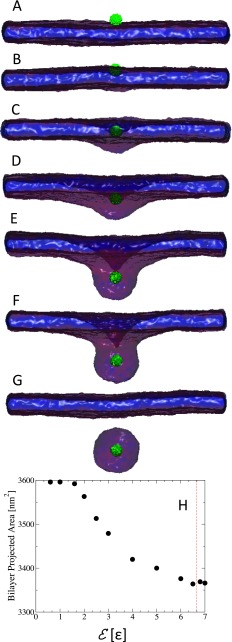
We performed a systematic set of simulations of single NPs with diameter, D, ranging between 2.8 nm and 17.4 nm, for varying values of the adhesion strength, . Equilibrium configurations of a small NP with D = 2.8 nm next to a tensionless bilayer for are shown in Figs. 1(a)-1(g). This figure shows that the NP adheres to the membrane at values of and that the NP is wrapped by the bilayer for between 1.3ϵ and 6.5ϵ, with the degree of wrapping that increases with increasing . The NP is almost completely wrapped at , and the NP is endocytosed at . The projected area of the bilayer, shown in Fig. 1(f), decreases with increasing as a result of wrapping of the NP. The value of adhesion energy at which the NP is endocytosed is inline with the prediction of Harries et al. of a protein with about 10 unit charges and of diameter 3 nm wrapped by a bilayer composed of anionic and neutral lipids.38
FIG. 1.
Sequence of equilibrium snapshots of a NP (green) with diameter D = 2.8 nm interacting with a tensionless lipid bilayer. Snapshots (A)–(G) correspond to the adhesion strength , 1.0, 1.3, 2.0, 4.0, 6.5, and 7.0ϵ, respectively. Graph (H) in the bottom shows the bilayer’s projected area, Ap, as a function of the adhesion strength.
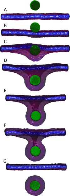
A similar set of configurations of NPs with a larger diameter, D = 8.7 nm, and at adhesion strength are shown in Fig. 2. As in the case of D = 2.8 nm, Fig. 2 shows that the larger NP is partially wrapped by the bilayer for a range of intermediate values of . The larger NP is endocytosed at , smaller than that for the case of D = 2.8 nm which is endocytosed at . This implies that the adhesion strength needed for wrapping and endocytosis of NPs decreases with increasing their size.
FIG. 2.
Sequence of equilibrium snapshots of a NP (green) with D = 8.7 nm interacting with a tensionless lipid bilayer. Snapshots (A)–(G) correspond to the adhesion strength , 0.40, 0.50, 0.60, 0.80, 0.90, and 1.0ϵ, respectively.
A series of equilibrium configurations of NPs with diameters ranging between 2.8 nm and 14.4 nm on tensionless bilayers and at an adhesion strength are displayed in Figs. 3(a)-3(d). This figure shows that while the smallest NP (D = 2.8 nm) simply adheres to the bilayer at this adhesion strength, with a small amount of contact lipids, NPs with 2.8 nm < D < 14.4 nm are wrapped by the bilayer with a degree of wrapping that increases with increasing the NP diameter. At D = 14.4 nm, the NP is fully endocytosed.
FIG. 3.
Sequence of equilibrium snapshots of a NP (green) with a bilayer at . (A)–(D) correspond to NP diameter D = 2.8 nm, 8.7 nm, 11.5 nm, and 14.4 nm, respectively.
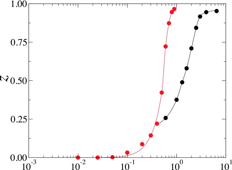
The degree of wrapping at equilibrium, defined as , where θ is the wrapping angle of the NP by the bilayer, shown in Fig. 4 quantitatively demonstrates that the NPs can be partially wrapped by the tensionless bilayer, a result that is apparently different from the theory of Deserno et al. which predicts that NPs are either unbound or completely wrapped by tensionless membranes.19,20 Fig. 4 also shows that the rate of change of z with increasing increases with increasing the NP’s diameter. These data suggest that large NPs should either be weakly wrapped by the bilayer for low values of or almost completely wrapped or endocytosed for large values of .
FIG. 4.
The degree of wrapping, z = (1 − cos θ)/2, vs adhesion strength for the case of D = 8.7 nm (red circles) and D = 2.8 nm (black circles). The red and black solid lines are guides to the eye for the red and black numerical data, respectively.
B. Phase diagram
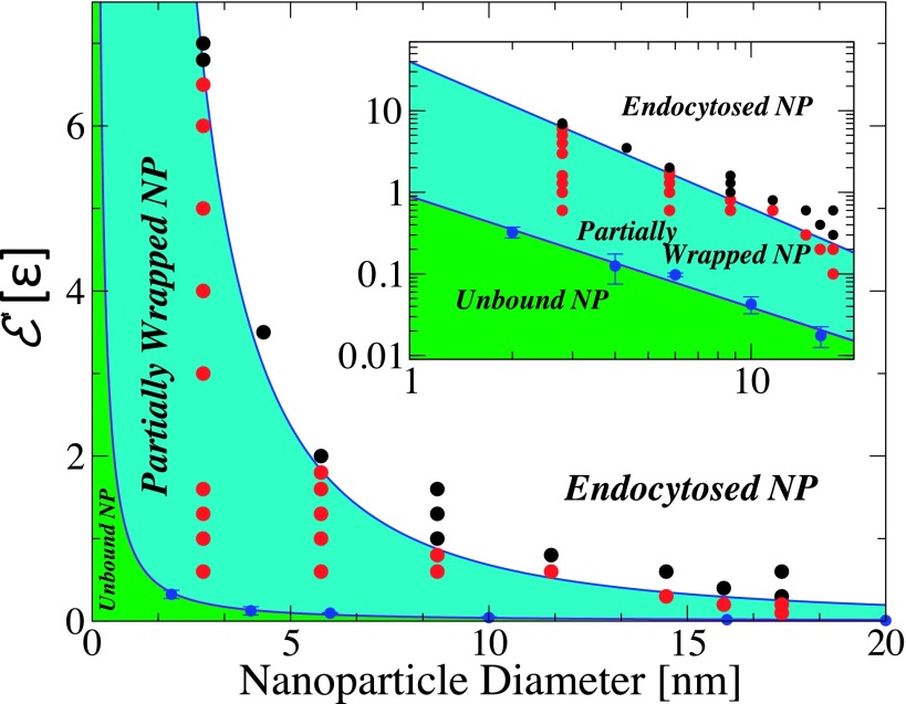
The results for different values of the NP diameter, D, and adhesion strength, , are summarized by the phase diagram in Fig. 5. As mentioned earlier, three main phases are observed: (I) a free or unbound-NP phase which occurs at low values of ; (II) an adhesion phase which occurs at intermediate values of ; and (III) an endocytosis phase at high values of , in which the NP is completely encapsulated by a vesicle that is detached from the bilayer. In the adhesion phase, the amount of membrane wrapping the NP increases with increasing , as shown earlier in Figs. 1 and 2. The NPs are almost fully wrapped by a bud right below the transition to the endocytosis phase, except for a small region around the bud’s neck. This phase diagram reemphasizes that the values of at the I-II and II-III phase transitions decrease with increasing the NP diameter, implying that it is easier for large NPs to (1) adhere to the bilayer and (2) to be endocytosed than small NPs. This is in qualitative agreement with the experimental work of Le Bihan et al.,17 and the mean field theoretical argument that the adhesion strength for I-II phase transition decreases with increasing the NP diameter.20 However, the main discrepancy between our numerical results and Deserno’s theory is that the NPs can be partially wrapped by the bilayer, despite the fact that the bilayer is tensionless.
FIG. 5.
Phase diagram of the adhesion of a spherical NP to tensionless lipid bilayer. Black circles represent the state of a fully endocytosed NP. Red circles represent states where the NP is bound to the lipid bilayer with partial wrapping. The blue line corresponds to the phase boundary between the two phases. The slope of the blue solid line is −1.8. Blue circles correspond to the phase boundary between the unbound NP-phase and the bound NP phase. The inset shows the same data in a log-log plot. The slope of the solid violet line is −1.3.
From Fig. 5, the transition line from the unbound phase to the bound phase follows , while the transition line from the bound phase to the endocytosis phase follows . This implies that the region where the NPs are partially bound narrows with increasing NPs diameter and should eventually disappear. The extrapolation of the simulation results to large NP diameters therefore agree well with the mean field arguments.19,20
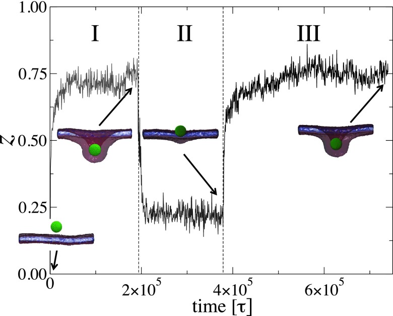
In order to determine whether the NP’s partial wrapping by the bilayer is an equilibrium state or a metastable state, we performed a series of simulations of a NP with diameter D = 8.7 nm and varied the adhesion strength as follows: First, the NP is equilibrated at . At this low adhesion strength, the NP is not bound to the bilayer. is then suddenly changed to 0.6ϵ, and the simulation is run for 1.95 × 10⁵τ (stage I). is then reduced to 0.4ϵ and the simulation is run for 1.85 × 10⁵τ (stage II). Finally, is increased again to 0.6ϵ and the system is let to equilibrate during 3.6 × 10⁵τ (stage III). The degree of wrapping, z, of this series of simulations is shown as a function of time in Fig. 6. Final configurations of each stage are also shown in Fig. 6. During stage I, the NP is fairly wrapped with z ≈ 0.75, corresponding to a wrapping angle about 120°. In stage II, the degree of wrapping is quickly reduced to z ≈ 0.2, corresponding to a wrapping angle about 53°. Note that the same wrapping angle at is obtained if the initial configuration is that of an unbound NP. In stage III, where is increased again to 0.6ϵ, the same degree of wrapping as in stage I is achieved. These series of simulations imply that the partially wrapped states at and 0.6ϵ are achieved regardless of the initial configuration. Therefore, the states of partially wrapped NPs are thermodynamically equilibrium states.
FIG. 6.
The degree of wrapping, , vs time for the case D = 8.7 nm. The system is simulated at in regime I, after an equilibration at . The system is then simulated at in regime II, then again at in regime III. The snapshots correspond to the final configurations for each regime.
IV. ELASTIC THEORY OF NANOPARTICLES ADHESION TO TENSIONLESS LIPID BILAYERS
Previous theoretical calculations of a spherical colloidal particle adhering to a tensionless bilayer, based on the Helfrich Hamiltonian, predict that the particle is either unbound or fully wrapped by the bilayer.19–21 In these calculations, it is assumed that the NP is much larger than the bilayer thickness and that the NP interacts with a bilayer via a contact potential energy. In the present study, we focus on the interaction between lipid bilayers and spherical NPs with diameter comparable to the thickness of the bilayer, and where the interaction between the bilayer and the NP is not merely a contact interaction. In what follows, the previous calculations are extended to the case of small NPs with short range interactions with the lipid bilayer.
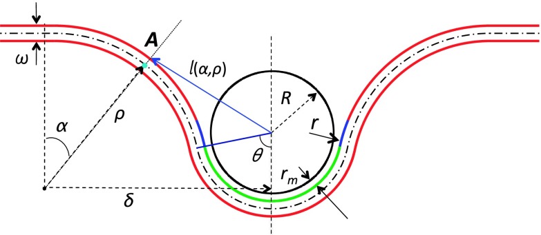
The geometry of the system, shown in Fig. 7, follows that used earlier by Deserno and Gelbart19 and Ruiz-Herrero et al.,21 except that in our case, the bilayer is assumed to have a finite thickness, ω. The portion of the top leaflet of the bilayer that is in direct contact with the NP is colored green. Due to the short range interaction between the NP and the bilayer, a portion of the neck region, shown in blue, also interacts with the NP. Since rm is the minimum of the interaction potential, the radius of curvature of the portion of the top leaflet that is in contact with the bilayer is R + rm. In the following calculations, we will assume that the top leaflet of the bilayer cannot be at a distance shorter than R + rm from the NP’s center of mass, and we will assume that the range of the interaction between any point within the NP and the hydrophilic portion of the bilayer is rm + λ. Furthermore, we will consider the case where λ < ω, implying that the NP can only interact with the top leaflet of the bilayer. Using the same general form of the potential used in our simulations, Eq. (2), the interaction between the NP and the top leaflet of the bilayer is then generalized to
| (10) |
FIG. 7.
The model bilayer-NP system used in the calculation. ω is the bilayer’s thickness. R = D/2 is the radius of the NP. The distance between the surface of the NP and the top leaflet in the contact region is rm. The portion of the top leaflet of the bilayer that is in direct contact with the NP is shown in green. The portion of the top leaflet that interacts with the NP but is not in direct contact with the NP is shown in blue. ρ is the radius of the rim of the bilayer. θ is the wrapping angle and 0 ≤ α ≤ θ. r, used in Eq. (10), is the distance between an arbitrary point in the NP and the top leaflet of the bilayer. l(α, ρ) is the distance between the center of the NP and a point within the rim of the top leaflet of the bilayer and is given by Eq. (20).
where r is the distance between an arbitrary point within the NP and the top leaflet of the bilayer. In our simulations, we considered the case of λ = rm (see Eq. (2)). λ will be varied to investigate the effect of the range of the interaction between the NP and the bilayer. We note here that we are allowing a thin shell within below the NP’s surface to interact with the lipid head groups. The thickness of this shell should be about the Thomas-Fermi screening length. For semiconducting particles, this screening length is , where ϵ is the dielectric constant, e is the carrier charge, and N is the doping number density. lFT can therefore be tuned through the doping density. In the case of metallic NPs, the screening length is about or lower 1 nm, about the length considered in our simulations.40
In Fig. 7, θ is the wrapping angle, from which the degree of wrapping is defined as z = (1 − cosθ)/2. The region of the bilayer, defined as rim, between the circle at which the top leaflet separates from the NP and the circle at which the bilayer recovers to the planar configuration is assumed to be a section of a torus.19,21 The free energy of the system is therefore written as
| (11) |
where the curvature free energy is given by
| (12) |
where we used the fact that the curvatures at a point A in the bilayer located in the rim at an angle α from the z-axis (turquoise dot in Fig. 7) are given by c1 = 1/ρ and c2 = − sinα/(δ − ρsinα), with
| (13) |
The adhesion energy of the bilayer which has contributions from both the contact and the rim regions of the bilayer is given by
| (14) |
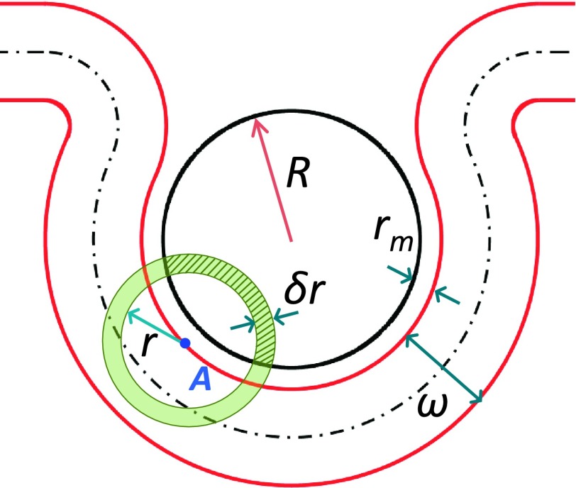
The adhesion energy of an element of area da at point A in the contact region of the top leaflet, as a result of interaction with the shaded region of the NP with volume dV(r) (Fig. 8), defined as the intersection between the NP and a spherical shell centered at A of radius r and thickness dr, is given by
| (15) |
FIG. 8.
Geometry of a partially wrapped NP showing the portion of a spherical shell (shaded green) of thickness δr and of volume δV within the NP located of radius r that interacts with a point A on the top leaflet of the bilayer. The element of volume dV is given in Eq. (16). Note that due to the short range of the interaction between the NP and the bilayer, the NP can only interact with a portion of the top leaflet that is close to it.
where σ and ν are the areal number density and volume number density of beads within the top leaflet of the bilayer and the NP, respectively. In Eq. (15),
| (16) |
with rm < r ≤ rm + λ and s = R + rm. In Eq. (15), the element of area da = 2π(R + rm)2sinα dα, with 0 ≤ α ≤ θ. The adhesion energy of the contact region of the bilayer is therefore given by
| (17) |
where
| (18) |
The contribution to the adhesion energy from the rim of the bilayer is calculated similarly and is given by
| (19) |
where the length l(α, ρ) (see Fig. 7) is given by
| (20) |
and
Using Eqs. (12)-(21), the net free energy of the system, Eq. (11), is then minimized numerically with respect to (θ, ρ) for varying values of the NP radius, R, and adhesion strength, .
A. Effect of NP’s diameter
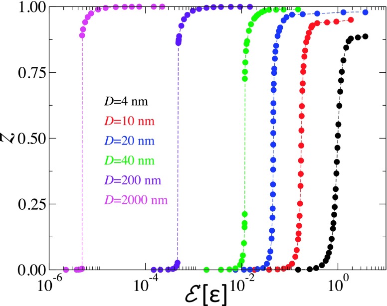
In Fig. 9, the degree of wrapping, z = (1 − cosθ)/2, is shown for NPs with diameter ranging between 4 and 2000 nm, for the case of κ = 50kBT and range of the NP-bilayer interaction, λ = rm. This figure shows that for NPs with D ≲ 20 nm, the degree of wrapping increases continuously with increasing the adhesion strength. The theoretical results for D ≲ 20 nm are in excellent qualitative agreement with the simulation results presented in Fig. 4. This includes the decrease in the slope of z vs. with decreasing the NP diameter.
FIG. 9.
The degree of wrapping, z = (1 − cos θ)/2, vs adhesion strength in the case of λ = rm and κ = 50kBT for NPs with D = 4 nm (black), 10 nm (red), 20 nm (blue), 40 nm (green), 200 nm (indigo), and 2000 nm (violet).
Fig. 9 shows that for larger NPs with D = 40, 200, and 2000 nm, the degree of wrapping exhibits a discontinuity, signaling a first-order transition from a phase where the NP is weakly wrapped by the bilayer for small values of and a phase where the NP is strongly wrapped by the bilayer for large values of . The size of the gap between weakly wrapped and strongly wrapped states decreases with decreasing the NP diameter. This implies that in the limit D ≫ ω, the NPs are either unbound or completely wrapped by the tensionless bilayer, in agreement with Deserno’s theory.20 It is worth noting that even for the case of D = 200 nm, the free energy of the weakly wrapped phase is at most 2.8kBT less than that of the unbound state, which means that thermal fluctuations will easily unbind the NP from the bilayer. We are currently extending our approach to allow for simulating NPs with large diameters in order to compare with our theoretical results.
B. Effect of range of interaction
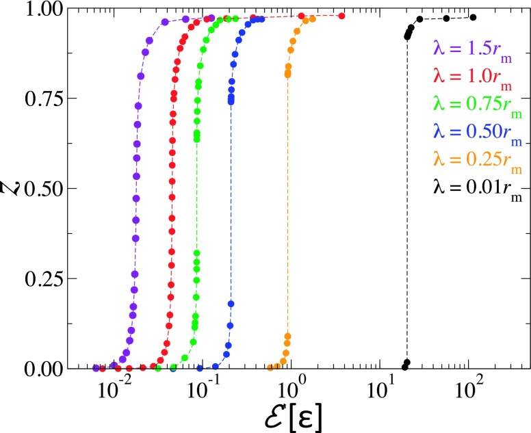
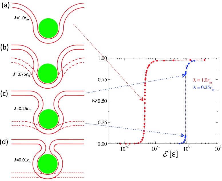
We now turn our attention to the effect of the range of interaction between the NP and the bilayer, λ, on the extent of wrapping. Fig. 10, which depicts the degree of wrapping for NPs with diameter D = 20 for different values of λ, shows that for this NP diameter, the wrapping degree increases continuously for λ ≳ rm. However, for smaller values of λ, z exhibits a discontinuity, with the size of the discontinuity gap increasing with decreasing λ. Theoretical bilayer profiles for the case of λ = 1.0 at z = 0.5 and at the lower and upper bounds of the gap in z for λ = 0.75, 0.25, and 0.01rm are shown in Fig. 11. The dashed and solid lines show the bilayer’s profiles at the lower and upper bounds of the gap, respectively. In the case of λ = 0.75rm, the bilayer degree of wrapping is substantial even at the lower bound of the gap. At λ = 0.25rm and 0.01rm, one notices a clear decrease/increase in the degree of wrapping at the lower/upper bound of the gap. In the case of λ = 0.01rm, the free energy of the upper bound of the weakly wrapped state is 0.65kBT less than that of the unbound state, which implies that for small values of λ, even small NPs are either unbound or strongly wrapped by the tensionless bilayer. The partial wrapping of the NPs in our simulations can therefore be explained by the fact that the range of the interaction in our simulations is finite instead of being infinitesimally small as in the previous theoretical calculations.20,21
FIG. 10.
The degree of wrapping vs. adhesion strength in the case of D = 20 nm and κ = 50kBT for values of λ corresponding to 0.01, 0.25, 0.5, 0.75, 1.0, and 1.5rm.
FIG. 11.
(a) Geometry of the bilayer partially wrapping a NP with D = 20 nm at the inflection point of the graph of the degree of wrapping, z, vs (violet data in Fig. 10) for the case of interaction range λ = 1.0rm. In (b)–(d), the dotted lines correspond to the configuration of the bilayer at the top of the branch of weakly wrapped states and the solid lines correspond to the configuration of the bilayer at the bottom of the branch of strongly wrapped states. (b)–(d) correspond to the case of λ = 0.75, 0.25, and 0.01rm, respectively. The graph on the left shows z for the case of λ = 1.0rm and λ = 0.25rm.
V. ADHESION OF NANOPARTICLES LEAD TO AN INCREASED CHAIN ORDER OF THE LIPID BILAYER
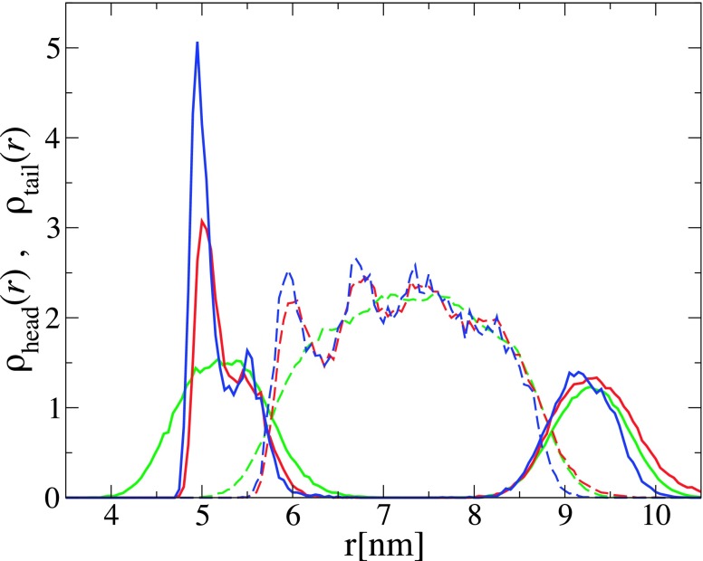
The transbilayer lipid distribution of the bilayer wrapping the NP is non-symmetric, as demonstrated by the density profiles of the lipid head and tail beads in Fig. 12 for the case of D = 8.7 nm and for and 0.6ϵ. At these values of , the NP is endocytosed by the bilayer. For comparison, the density profiles of lipids for the case of an empty vesicle with the same diameter are also shown in Fig. 12. This figure shows that the density of lipids in the leaflet in contact with the NP is significantly higher than that of the outer leaflet and that the density profile of the hydrophobic tails exhibits substantial oscillations which increase in amplitude with increasing the adhesion strength. This is indicative of an increased chain order of the lipids next to the NP. Similar results were reported by Xing and Faller39 from their simulations of lipid bilayer supported by planar substrates. We note that we did not find any indication of a positional order of the lipids in contact with the NP. This is due to the fact that positional order (crystallinity) requires faceting of the vesicle31 which is prevented by the strong interaction between the spherical NP and the lipids which favors a spherical shape.
FIG. 12.
Radial number density profiles of the head and tail beads of lipids belonging to the bilayer that is in contact with the NP, within . The solid and dashed curves correspond to the profiles of the lipid head and tail beads, respectively. The density profiles are measured from the center of mass of the NP. The blue and red lines correspond to a NP with D = 8.7 nm at and 0.6ϵ, respectively. The green curves correspond to an empty vesicle with the same diameter.
Since the portion of the leaflet that is in contact with the NP has a higher density of lipids than that of the bare bilayer, the conformational entropy of the lipid molecules in contact with the NP is decreased, and as a result, the bending modulus of the region of the bilayer in contact with the NP must be higher than that of the bare bilayer. The calculations in Sec. IV are then extended to account for the fact that the bending modulus of the bilayer is heterogeneous. Let κ and κ′ be the bending moduli of the bare region of the bilayer and the region of the bilayer in contact with the NP, respectively. Furthermore, since the boundaries of the two regions of the bilayer depend on the degree of wrapping, the Gauss-Bonnet theorem does not apply,41 and the Gaussian bending terms in the free energy have to be taken into account. Eq. (12) is then generalized to
| (21) |
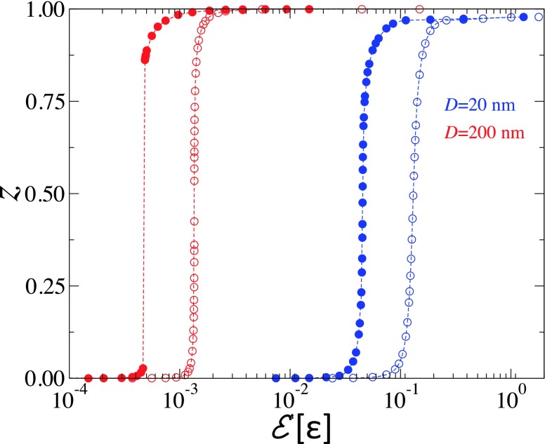
where and are the Gaussian bending moduli for the bare bilayer and the region of the bilayer in direct contact with the NP. To continue our calculations, we will assume that and .42 The free energy, composed of the curvature energy, given by Eqs. (21) and (13), is then minimized with respect to the wrapping angle θ and the radius ρ. The wrapping angle for the case where κ′ = κ = 50kBT and the case of κ′ = 5κ = 250kBT is shown in Fig. 13 for NPs with D = 20 and 200 nm. We note that the value of κ′ = 5κ is arbitrary. The goal here is to show the effect of a stiffer region of the bilayer that is in contact with the NP. This figure shows that the increased bending modulus of the region of the bilayer in direct contact with the NP leads to a reduction in the discontinuity of the wrapping angle at intermediate values of adhesion strength. The effect of an increased bending modulus of the contact region therefore further enhances the effect of the finite range of interaction between the NP and the bilayer, stabilizing partially wrapped NPs.
FIG. 13.
The wrapping parameter z = 1 − cos θ vs adhesion strength at λ = 1.0 nm. Solid symbols correspond to κ = κ′ = 50kBT and the open symbols correspond to κ = 50kBT and κ′ = 250kBT. Blue and red symbols correspond to D = 20 and 200 nm, respectively.
VI. SUMMARY AND CONCLUSIONS
The interaction of small spherical NPs with tensionless membranes is investigated numerically through molecular dynamics simulations of an implicit solvent model for self-assembled lipid membranes.29 We particularly focussed on NPs with diameters comparable to the thickness of the lipid bilayer. We found that NPs are unbound for low values of the adhesion strength, they are partially wrapped for intermediate values of the adhesion strength with a degree of wrapping that increases with increasing the adhesion strength, and they are endocytosed for large values of the adhesion strength. The transition adhesion strengths from the unbound to the wrapped states and from the wrapped to the endocytosed states decrease with increasing the NP size.
The partially wrapped states are shown to be thermodynamically equilibrium states using annealing simulations. These results, which are different from those of the theory of Deserno et al.,19,20 were explained in terms of a generalized elastic theory based on the Helfrich Hamiltonian. In this theory, the interaction between the NP and the lipid bilayer is short ranged, accounting for interaction between the NP and part of the neck of the lipid bilayer. We found that this lead to partial wrapping of the NP by the bilayer. An explanation of this effect is that in the case of a tensionless bilayer that interacts with a NP only when both are in contact, while the adhesion energy is proportional to the contact area the curvature energy is constant. The free energy is then minimized when the contact area is maximized, which corresponds to a fully wrapped NP. However, in our case, the adhesion energy is no longer proportional to the contact area due to the additional interaction with a portion of the neck region of the bilayer. The extent of partial wrapping is amplified with decreasing the size of the NP and/or the range of the interaction, λ. For a given range of the interaction of the NP with the bilayer, and for small NPs, the degree of wrapping increases continuously until full wrapping. However, there exist a threshold NP size D*(λ), beyond which there exist a discontinuity in the degree of wrapping. Namely, NPs with D > D*(λ) are either weakly wrapped for small adhesion strength or strongly wrapped for large adhesion strength. The gap in the degree of wrapping increases with increasing the NP diameter. Furthermore, we found that the threshold D*(λ) decreases with decreasing λ, implying that in the limit of contact interaction, i.e., for λ = 0, the NP is either unbound or fully bound, in agreement with the predictions of Deserno et al. For D ≫ D*(λ), the free energy of the weakly wrapped states is about kBT or smaller, implying that thermal fluctuations should easily unbind the NP.
In order to see why partially wrapped states are expected when non-contact interactions between the NP and the lipids are accounted for, we consider a partially wrapped NP with a contact area A. The excess free energy of the system can approximatively be written as , where w is the contact adhesion energy density, is an effective adhesion energy density of the non-contact region, and a is the area of the non-contact region of the bilayer that interacts with the NP. Note that in principle w′ depends on the shape of the non-contact region of the bilayer. In the absence of non-contact interaction, wrapping does not occur if w < 8κ/D2. However, the presence of in the free energy can overcome the increase in free energy due to curvature of the contact region and lead to stable partially wrapped states.
The model used in the simulations accounts for the solvent implicitly. The use of an implicit solvent in the present numerical study is motivated by the fact that using a model with explicit solvent to systematically study interactions between a NP and lipid bilayers is computationally too costly at the moment. While the present model cannot properly describe the kinetics of wrapping and endocytosis due to the absence of explicit solvent, it should capture the equilibrium phase behavior of NPs wrapping and endocytosis by lipid membranes.
The simulations showed that the adhesion of the NP leads to an increased conformational order of the lipids in contact with the NP. This implies that the bending rigidity of the bilayer in contact with the NP is higher than that of the bare bilayer. The extension of the elastic theory accounting for non-uniformity of both the bending modulus and the saddle-splay modulus predicts further enhancement of partially wrapped states, as demonstrated by the decrease in the gap between weakly and strongly wrapped states. We note the fact that interactions between the NPs and the lipids are not merely contact interaction, the area compressibility modulus should become wave-vector-dependent. This could lead to a wave-vector-dependent tension and therefore a residual tension even if the tension of the bilayer is set to zero. We also note interactions up to few nanometers in range between negatively charged NPs and zwitterionic lipid bilayers, such as dipalmitoylphosphatidylcholine bilayers, in solutions with biologically relevant counter-ion concentrations justify the use of the relatively long-range interactions.43
The Helfrich Hamiltonian should be valid for low curvatures, while the theoretical calculations in the present article were performed for curvatures about the thickness of the bilayer. It is clear that at such high curvatures, higher order expansion in curvature of the bending energy may be required. The results at high curvatures obtained here should therefore be only qualitatively correct. The fact that the width of the gap between the weakly wrapped states and strongly wrapped states decreases with decreasing the NP diameter implies that at some small NP diameter, the gap is expected to disappear at some small NP diameter.
Since the NPs in our simulations are comparable in size to the thickness of the lipid bilayer, we did not observe a gap in the degree of wrapping. Clearly, further simulations on larger NPs and therefore larger bilayers are needed to verify whether a gap in the degree of wrapping emerges beyond a certain diameter. Such simulations are planned in the near future.
In the present study, we only considered the case of a single nanoparticle and therefore neglected any cooperative effects. Saric and Cacciuto44 showed numerically different types of nanoparticles’ aggregation depending on the bending modulus and the adhesion strength. In particular, they found that the nanoparticles aggregate into linear chains for moderate values of the bending modulus or adhesion strength. However, for high bending modulus and adhesion strength or low bending modulus and adhesion strength, the nanoparticles aggregate into a triangular lattice. For very high adhesion strength, the nanoparticles remain isolated. Whether the nanoparticles can be internalized by the bilayer in the form of isolated particles or aggregates remains unclear.
Acknowledgments
The authors thank P. B. Sunil Kumar for stimulating discussions. This work was supported by grants from the National Institute of General Medical Sciences of the National Institutes of Health (No. R15GM106326), the National Science Foundation (No. EPS-1003083), and by The University of Memphis Faculty Research Grant Fund. The later support does not necessarily imply endorsement by the University of research conclusions. All simulations were performed on computers of the High Performance Computing Facility at the University of Memphis.
REFERENCES
- 1.Chithrani D. B., Mol. Membr. Biol. 27, 299–311 (2010). 10.3109/09687688.2010.507787 [DOI] [PubMed] [Google Scholar]
- 2.Berry C. C. and Curtis A. S. G., J. Phys. D: Appl. Phys. 36, R198–R206 (2003). 10.1088/0022-3727/36/13/203 [DOI] [Google Scholar]
- 3.Zhang L. W., Yu W. W., Colvin V. L., and Monteiro-Riviere N. A., Toxicol. Appl. Pharmacol. 228, 200–211 (2008). 10.1016/j.taap.2007.12.022 [DOI] [PubMed] [Google Scholar]
- 4.Kulkarni G. S. and Zhang Z. H., Nano Lett. 12, 719–723 (2012). 10.1021/nl203666a [DOI] [PubMed] [Google Scholar]
- 5.Kim E., Kim D., Jung H. et al. , Angew. Chem., Int. Ed. 49, 4405–4408 (2010). 10.1002/anie.201000818 [DOI] [PubMed] [Google Scholar]
- 6.Tkachenko A. G., Xie H., Liu Y. et al. , Bioconjugate Chem. 15, 4820490 (2004). 10.1021/bc034189q [DOI] [PubMed] [Google Scholar]
- 7.Alivisatos P., Nat. Biotechnol. 22, 47–52 (2004). 10.1038/nbt927 [DOI] [PubMed] [Google Scholar]
- 8.Selvan S. T., Tan T. T. Y., Yi D. K., and Jana N. R., Langmuir 26, 11631–11641 (2010). 10.1021/la903512m [DOI] [PubMed] [Google Scholar]
- 9.West J. L. and Hala N. J., Annu. Rev. Biomed. Eng. 5, 285–292 (2003). 10.1146/annurev.bioeng.5.011303.120723 [DOI] [PubMed] [Google Scholar]
- 10.Davis M. E., Zuckermann J. E., Choi C. H. J., Selingson D., Tolcher A., Alabi C. A., Yen Y., Heidel J. D., and Ribas A., Nature 464, 1067 (2010). 10.1038/nature08956 [DOI] [PMC free article] [PubMed] [Google Scholar]
- 11.Jain K. K., Technol. Cancer Res. Treat. 4, 407–416 (2005). 10.1177/153303460500400408 [DOI] [PubMed] [Google Scholar]
- 12.Lewinski N. V., Colvin V., and Drezek R., Small 4, 26–49 (2008). 10.1002/smll.200700595 [DOI] [PubMed] [Google Scholar]
- 13.Conner S. D. and Schmid S. L., Nature 422, 37–44 (2003). 10.1038/nature01451 [DOI] [PubMed] [Google Scholar]
- 14.Lamaze C. et al. , Mol. Cell 7, 661–671 (2001). 10.1016/S1097-2765(01)00212-X [DOI] [PubMed] [Google Scholar]
- 15.Nichols B. J. and Lippincott-Schwartz J., Trends Cell Biol. 11, 406–412 (2001). 10.1016/S0962-8924(01)02107-9 [DOI] [PubMed] [Google Scholar]
- 16.Rothen-Rutishauser B. M., Schürch S., Haenni B., Kapp N., and Gehr P., Environ. Sci. Technol. 40, 4353–4359 (2006). 10.1021/es0522635 [DOI] [PubMed] [Google Scholar]
- 17.Le Bihan O., Bonnafous P., Marak L., Bickel T., Trépout S., Mornet S., De Haas F., Talbot H., Taveau J.-C., and Lambert O., J. Struct. Biol. 168, 419–425 (2009). 10.1016/j.jsb.2009.07.006 [DOI] [PubMed] [Google Scholar]
- 18.Tazhara K., Tadokori S., Kawashima Y., and Hirashima N., Langmuir 28, 7114–7118 (2012). 10.1021/la300902z [DOI] [PubMed] [Google Scholar]
- 19.Deserno M. and Gelbart W. M., J. Phys. Chem. B 106, 5543–5552 (2002). 10.1021/jp0138476 [DOI] [Google Scholar]
- 20.Deserno M. and Bickel T., Europhys. Lett. 62, 767–773 (2003). 10.1209/epl/i2003-00438-4 [DOI] [Google Scholar]
- 21.Ruiz-Herrero T., Velasco E., and Hagan M. F., J. Phys. Chem. B 116, 9595 (2012). 10.1021/jp301601g [DOI] [PMC free article] [PubMed] [Google Scholar]
- 22.Yi X., Shi X., and Gao H., Phys. Rev. Lett. 107, 098101 (2011). 10.1103/PhysRevLett.107.098101 [DOI] [PubMed] [Google Scholar]
- 23.Yi X. and Gao H., Soft Matter 11, 1107–1115 (2015). 10.1039/C4SM02427C [DOI] [PubMed] [Google Scholar]
- 24.Dasgupta S., Auth T., and Gompper G., Soft Matter 9, 5473–5482 (2013). 10.1039/C3SM50351H [DOI] [Google Scholar]
- 25.Dasgupta S., Auth T., and Gompper G., Nano Lett. 14, 687–693 (2014). 10.1021/nl403949h [DOI] [PubMed] [Google Scholar]
- 26.Vácha R., Martinez-Veracoechea F. J., and Frenkel D., Nano Lett. 11, 5391–5395 (2011). 10.1021/nl2030213 [DOI] [PubMed] [Google Scholar]
- 27.Huang C., Zhang Y., Gao H., and Zhang S., Nano Lett. 13, 4546–4550 (2013). 10.1021/nl402628n [DOI] [PubMed] [Google Scholar]
- 28.Helfrich W., Z. Naturforsch. 28, 693 (1973). [DOI] [PubMed] [Google Scholar]
- 29.Revalee J. D., Laradji M., and Sunil Kumar P. B., J. Chem. Phys. 128, 035102 (2008). 10.1063/1.2825300 [DOI] [PubMed] [Google Scholar]
- 30.Spangler E. J., Harvey C. W., Revalee J. D., Sunil Kumar P. B., and Laradji M., Phys. Rev. E 84, 051906 (2011). 10.1103/PhysRevE.84.051906 [DOI] [PubMed] [Google Scholar]
- 31.Spangler E. J., Sunil Kumar P. B., and Laradji M., Soft Matter 8, 10896 (2012). 10.1039/c2sm25974e [DOI] [PubMed] [Google Scholar]
- 32.Farago O., J. Chem. Phys. 119, 596 (2003). 10.1063/1.1578612 [DOI] [Google Scholar]
- 33.Brannigan G., Tamboli A. C., and Brown F. L. H., J. Chem. Phys. 121, 3259 (2004). 10.1063/1.1770569 [DOI] [PubMed] [Google Scholar]
- 34.Wang Z. J. and Frenkel D., J. Chem. Phys. 122, 234711 (2005). 10.1063/1.1927509 [DOI] [PubMed] [Google Scholar]
- 35.Cooke I. R., Kremer K., and Deserno M., Phys. Rev. E 72, 011506 (2005). 10.1103/PhysRevE.72.011506 [DOI] [PubMed] [Google Scholar]
- 36.Laradji M. and Sunil Kumar P. B., J. Chem. Phys. 132, 224902 (2005). 10.1063/1.2102894 [DOI] [PubMed] [Google Scholar]
- 37.Grest G. S. and Kremer K., Phys. Rev. A 33, 3628 (1986). 10.1103/PhysRevA.33.3628 [DOI] [PubMed] [Google Scholar]
- 38.Harries D., Ben-Shaul A., and Scleifer I., J. Phys. Chem. B 108, 1491 (2004). 10.1021/jp036501z [DOI] [Google Scholar]
- 39.Xing C. and Faller R., J. Chem. Phys. 131, 175104 (2009). 10.1063/1.3262315 [DOI] [PubMed] [Google Scholar]
- 40.Krcmar M., Saslow W. M., and Zangwill A., J. Appl. Phys. 93, 3490 (2003). 10.1063/1.1540711 [DOI] [Google Scholar]
- 41.do Carmo M., Differential Geometry of Curves and Surfaces (Prentice Hall, 1976). [Google Scholar]
- 42.Hu M., Briguglio J. I., and Deserno M., Biophys. J. 102, 1403 (2012). 10.1016/j.bpj.2012.02.013 [DOI] [PMC free article] [PubMed] [Google Scholar]
- 43.Velikonja A., Santhosh P. B., Gongadze E., Kulkarni M., Elersic K., Perutkova S., Kralj-Iglic V., Ulrih N. P., and Iglic A., Int. J. Mol. Sci. 14, 15312 (2013). 10.3390/ijms140815312 [DOI] [PMC free article] [PubMed] [Google Scholar]
- 44.Saric S. and Cacciuto A., Phys. Rev. Lett. 108, 118101 (2012). 10.1103/PhysRevLett.108.118101 [DOI] [PubMed] [Google Scholar]


