

Abstract
Objective
The somatosensory evoked potential (SEP) elicited by median nerve stimulation consists of the N20 peak together with the concurrent high frequency oscillation (HFO, > 500 Hz). We describe the conditions for HFO detection in ECoG and scalp EEG in intraoperative recordings.
Methods
During neurosurgical interventions in six patients under propofol anesthesia, the SEP was recorded from subdural electrode strips (15 recordings) and from scalp electrodes (10/15 recordings). We quantified the spatial attenuation of the Signal-to-Noise Ratio (SNR) of N20 and HFO along the contacts of the electrode strip. We then compared the SNR of ECoG and simultaneous scalp EEG in a biophysical framework.
Results
HFO detection under propofol anesthesia was demonstrated. Visual inspection of strip cortical recordings revealed phase reversal for N20 in 14/15 recordings and for HFO in 10/15 recordings. N20 had higher maximal SNR (median 33.5 dB) than HFO (median 23 dB). The SNR of N20 attenuated with a larger spatial extent (median 7.2 dB/cm) than the SNR of HFO (median 12.3 dB/cm). We found significant correlations between the maximum SNR (rho = 0.58, p = 0.025) and the spatial attenuation (rho = 0.86, p < 0.001) of N20 and HFO. In 3/10 recordings we found HFO in scalp EEG. Based on the spatial attenuation and SNR in the ECoG, we estimated the scalp EEG amplitude ratio N20/HFO and found significant correlation with recorded values (rho = 0.65, p = 0.049).
Conclusions
We proved possible the intraoperative SEP HFO detection under propofol anesthesia. The spatial attenuation along ECoG contacts represents a good estimator of the area contributing to scalp EEG. The SNR and the spatial attenuation in ECoG recordings provide further insights for the prediction of HFO detectability in scalp EEG. The results obtained in this context may not be limited to SEP HFO, but could be generalized to biological signatures lying in the same SNR and frequency range.
Keywords: EEG, ECoG, Neurosurgery, Propofol, SEP, HFO burst, Sigma burst
Highlights
-
•
Somatosensory evoked HFOs can be recorded in ECoG and scalp EEG intraoperatively under propofol anesthesia.
-
•
The HFO amplitude in ECoG attenuated to noise level over a smaller spatial scale than the N20 amplitude.
-
•
The spatial attenuation of the cortical SNR directly relates to the noise level and to the scalp EEG amplitude.
-
•
Parameters extracted from ECoG allowed estimating the ratio of N20/HFO amplitude in scalp EEG.
1. Introduction
In recent years, the spectral range of invasive and non-invasive EEG recordings has been extended beyond the traditional limit of around 100 Hz. An increasing number of studies has been targeting the detection and characterization of pathological high frequency oscillations (pHFOs, 80–500 Hz) as a biomarker for the identification of the epileptogenic zone (Jacobs et al., 2012, Zijlmans et al., 2012). pHFO detection in scalp EEG represents a major challenge, given the critical Signal-to-Noise Ratio (SNR). Moreover, the correlation between cortical and scalp EEG recordings is a topic of current interest (von Ellenrieder et al., 2014b, Zelmann et al., 2014). In order to study the detectability of physiological activity in the pHFO spectral range, we investigated the high frequency components associated to the early somatosensory evoked potential (SEP) elicited in human EEG by median nerve current stimulation.
The SEP contains contributions in different temporal and spectral domains. The early low-frequency thalamic (P16) and cortical (N20) responses concur with a high frequency oscillation (HFO, > 500 Hz) with an amplitude of few hundreds of nV peak-to-peak (pp), which has first been recorded in the scalp EEG with a large number of averages (Cracco and Cracco, 1976, Curio et al., 1994, Ozaki and Hashimoto, 2011). The SEP HFO has been recorded also by the subdural electrocorticogram (ECoG) in humans (Kojima et al., 2001, Maegaki et al., 2000, Sakura et al., 2009).
The SEP is a standard tool for intraoperative neurophysiological monitoring. The SEP N20 is generated from area 3b in the primary somatosensory area (Lüders et al., 1983). In the spatial distribution of the N20, a phase reversal occurs over the central sulcus, i.e. recordings from contacts in proximity of the central sulcus show opposite N20 polarity over sensory and motor cortex. For this reason, N20 phase reversal analysis is used to localize the central sulcus when lesions are operated on in the sensorimotor region (Gregorie and Goldring, 1984).
The detectability of physiological and pathological HFOs in scalp EEG is still under debate. In particular, it is not yet clear how the size of the contributing cortical area and the noise level affect the detectability of HFO in scalp EEG (von Ellenrieder et al., 2014b, Zelmann et al., 2014). We investigated the influence of these two parameters on the relationship between ECoG and scalp EEG in the SEP biophysical framework. By simultaneously recording N20 and HFO in ECoG and scalp EEG, we explored their detectability in EEG in terms of SNR and spatial integration over the cortical tissue.
2. Patients and method
2.1. Patients
We included six patients (five men; median age 54 years, range 38–69 years), who underwent tumor surgery at the Neurosurgery Department of the University Hospital in Zurich, from April 2014 to December 2014, and where subdural electrode strips were placed to locate the central sulcus by the phase-reversal SEP (Table 1). Collection of personal patient data and retrospective scientific workup was approved by the institutional ethics review board (Kantonale Ethikkommission KEK-ZH-Nr. 2012–0212) and collection of patients' written informed consent was waived.
Table 1.
Clinical data.
| Patient | Number of recordings | Age | Sex | Number of electrode contacts | Phase reversal | Number of averages median [range] |
|---|---|---|---|---|---|---|
| 1 | 1 | 54 | M | 4 | No | 4008 |
| 2 | 4 | 38 | M | 6 | Yes | 4179 [3332–10000] |
| 3 | 5 | 62 | M | 6 | Yes | 1405 [367–5149] |
| 4 | 2 | 44 | M | 6 | Yes | 5131 [4287–5976] |
| 5 | 2 | 69 | F | 6 | Yes | 3504 [2008–5000] |
| 6 | 1 | 53 | M | 5 | Yes | 1331 |
2.2. Anesthesia management
Following our standard protocol for neurosurgical interventions, anesthesia was induced with intravenous application of Propofol (1.5–2 mg/kg) and Fentanyl (2–3 μg/kg). The intratracheal intubation was facilitated by Atracurium (0.5 mg/kg). Anesthesia was maintained with Propofol (5–10 mg/kg/h) and Remifentanil (0.1–2 μg/kg/min). Atracurium was omitted after intubation because of its interference with electrophysiological monitoring and mapping of motor function.
2.3. Scalp EEG electrodes
After the induction of anesthesia, corkscrew electrodes (www.inomed.com) were placed in the scalp at the sites C3 and C4 of the international 10/20 system. Depending on the location of the surgical field, the position of the electrodes had to be adjusted. A corkscrew electrode was placed at AFz as recording reference.
2.4. ECoG electrodes and implantation sites
Subdural strip electrodes (4 or 6 contacts, contact diameter 6 mm with a 5 mm exposure, spacing between contact centers 10 mm, Ad-Tech Medical) were placed after craniotomy in order to localize the central sulcus. Depending on surgical restrictions, the strip was placed directly on the sensory cortex, motor cortex, or both. The strip locations were documented by video recordings. In four patients, we recorded from several implantation sites (Table 1).
2.5. Stimulation
We stimulated the median nerve at the patient's wrist, contralaterally to the recording side, with current square-wave pulses of 200 μs (OSIRIS NeuroStimulator, Inomed Medizintechnik GmbH, Germany, www.inomed.com). The current was set fairly above the motor threshold. The stimulation rate was chosen in the range 0.7–12.7 Hz.
2.6. Data acquisition
Data was recorded with the Inomed ISIS System (Inomed Medizintechnik GmbH) at sampling rate of 20 kHz with 5 Hz high pass and 5000 Hz low pass filters.
Data was recorded against AFz and then re-referenced off-line to a subdural electrode for further analysis. The data window extended to 84 ms post-stimulus. Single trial SEP waveforms were averaged upon acquisition (median 4003 single trials, range 367–10000).
2.7. Analysis of data from individual electrode contacts
Data analysis was performed with custom scripts in MATLAB R2013b (www.Mathworks.com). We first re-referenced the signals from subdural electrode contacts to the signal from the contact with the largest distance to the central sulcus.
To avoid filter ringing, stimulus artifacts were removed in each channel by linear interpolation from 0 to + 10 ms after the stimulus onset. To identify distinct spectral components in the unfiltered signal, we performed time-frequency analysis with the Stockwell-transform (Stockwell et al., 1996). We rendered visible wide amplitude variations in the spectral range spanning from near-DC to 2 kHz in the time-frequency representation.
The SEP was filtered and analyzed in a broader spectral range (30–1000 Hz) for the N20 and in a high-passed spectral range (500–1000 Hz) for the HFO. We used Infinite Impulse Response (IIR, 2nd order, Butterworth type, response roll-off − 12 dB per octave), forward and reverse filtering in order to avoid phase distortion. We tested the filter responses on synthetic signals.
We defined the amplitude of the N20 signal for each channel as the extreme around 20 ms after the stimulus. The extreme was negative for channels over sensory cortex and positive for channels over motor cortex. The latency of the extreme was taken as the latency of the N20 peak.
We defined the HFO amplitude as the RMS value of the filtered signal in a range from − 5 to + 5 ms around the N20 peak. We defined the HFO latency as the latency of the peak of the Hilbert envelope calculated over the filtered signal.
2.8. Analysis of spatial attenuation in the electrode strip
We plotted the SNR of N20 and HFO as a function of the distance between electrode contacts in the strip. To compute the attenuation, we first fitted the spatial attenuation τ with an exponential model and then expressed the attenuation coefficient in dB/cm. The term “attenuation” refers to the spatial attenuation of the SNR in the ECoG from its maximum to noise level, while the term “reduction” is used to discuss the effects of anesthesia.
2.9. Statistical analysis
Distributions of the SNR, latency and attenuation of N20 and HFO were compared by the Wilcoxon signed-rank test, Wilcoxon rank-sum test and Spearman's rank-order correlation. Distributions were characterized by mean ± standard deviation (SD) or median and range. Statistical significance was established for p < 0.05.
2.10. Comparison between ECOG and scalp EEG recordings
In order to compare ECoG and scalp EEG recordings, we analyzed the decrease of the SNR for both N20 and HFO in terms of dampening across the skull. For each patient, we selected one representative recording, with visible scalp HFO (SNR > 1.5) when available. The dampening factor δN20 for the N20 was calculated as the ratio between the N20 peak from the strip contacts placed over the sensory cortex and the corresponding N20 peak from the scalp EEG. For the HFO, we defined the dampening factor δHFO as the ratio between the ECoG and the EEG peak amplitudes at the same latency.
2.11. Spatial attenuation as an estimator of the noise level: a simulated scenario
In order to explain the role of the spatial attenuation coefficient in terms of detectability, we provide a simulated scenario, showing the dependence of the exponential fit on the noise level. We simulated a strip covering 5 cm of cortex, with 51 contacts, 1 mm apart each and added Gaussian white noise with zero mean and standard deviation equal to 1, which is fairly higher than in our ECoG recordings. We varied the SNR from 11 to a maximum of 47. For each SNR we expressed the fitted decay constant τ in terms of spatial attenuation and determined the distance at which the exponential fit reaches the noise level (SNR = 1). From this distance we estimated the cortical area in which the signal was above noise level.
2.12. Spatial attenuation as an estimator of cortical area contributing to scalp EEG
The parameters involved in the prediction of the detectability over the scalp are the source intensity and the contributing cortical area. They can be quantified respectively in terms of maximum peak amplitude and cortical area with SNR > 1. For the peak amplitude we used the maximum voltage, recorded for N20 and HFO, labeled as AECoG. The contributing area can be estimated using the amplitude decay τ along consecutive contacts. We were interested in testing whether the ratio between AEEG for N20 and HFO computed for the scalp EEG matches the experimental results. Therefore, we estimated the amplitude AEEG by
| (1) |
where
- AECoG
maximum ECoG amplitude [μV]
- τ
attenuation coefficient [1/cm]
- x
distance from the strip contact with maximum ECoG amplitude [cm]
- S
cortical surface of integration
3. Results
We, first, present the ECoG evoked responses recorded under propofol anesthesia. We evaluate the spatial attenuation in terms of the SNR and statistically describe the relation between N20 and HFO. Then, we consider the relation to the scalp EEG and computationally test the role of the spatial attenuation in order to evaluate the cortical area contributing to the scalp EEG HFO.
3.1. N20 and HFO analysis: an example
N20 and HFO traces for patient 3 are shown in Fig. 1A and B, respectively. The corresponding Stockwell transform is depicted in Fig. 1C. The electrode strip covered the central sulcus so that electrode contact 6 was on postcentral cortex and contacts 1–5 were on precentral cortex (Fig. 1H). The location of the strip becomes evident from the polarity of the N20 traces (Fig. 1A), which showed a phase reversal between channels 5 and 6. The SEP had its maximum response at channel 6 with the peak N20 at 23.9 ms after the stimulus. The high-pass filtered data (Fig. 1B) show the HFO with a maximum in channel 6. The time-frequency representation of unfiltered signals (Fig. 1C) shows a distinct HFO above 500 Hz in channels 5 and 6.
Fig. 1.

N20 and HFO recorded from patient 3.
(A) Median nerve somatosensory evoked potential (SEP) at channels 2–6. N20 traces (high-pass 30 Hz, low pass 1000 Hz) from 10 to 60 ms after the stimulus. The signals were re-referenced against signals from electrode contact 1.
(B) The HFO appears in the high-pass filtered (> 500 Hz) SEP response with the maximum on sensory cortex (channel 6).
(C) Time-frequency representation of the non-filtered SEP response using the Stockwell-transform. The HFO component is separated from the low frequency activity by a trough.
(D) Phase reversal of the N20 between channel 5 (motor cortex, blue) and 6 (sensory cortex, red). The N20 peak appears at 23.7 ms.
(E) Phase reversal of the HFO between channel 5 and channel 6. HFO traces are in opposite phase before the peak of N20. After the N20 peak, the phases of the traces tend to synchronize.
(F, G) Spatial attenuation of Signal-to-Noise Ratio (SNR) for N20 and HFO. Channel 5 at x = 0 cm, channel 6 on sensory cortex is not included in analysis. The red crosses represent the SNR for channels 5, 4, 3 and 2. The blue line is the least square fit to an exponential function. The N20 attenuates to noise level (SNR = 1) with a larger spatial extent (exponential space constant 0.9 cm, attenuation 10.2 dB/cm) than the HFO (exponential space constant 0.5 cm, attenuation 18.2 dB/cm).
(H) Reconstruction of the electrode strip placement. Electrode contacts 1–5 are located on precentral cortex and contact 6 on sensory cortex. Anterior a; posterior p.
The phase reversal between channels 5 and 6 is shown in more detail for the N20 (Fig. 1D). The N20 peaks at 23.7 ms. In the interval 20–28 ms, the Spearman rank-order correlation between N20 traces was − 0.9 (p < 0.001), which indicates a clear phase reversal.
The phase reversal for the HFO (Fig. 1E) also occurred between channels 5 and 6. HFO traces were in opposite phase before the peak of N20 (Spearman's rho = − 0.4, p = 0.001 in the range 20–23.9 ms). After the N20 peak, the phases of the traces tended to synchronize (rho = 0.2, p = 0.053 in the range 23.9–28 ms).
The SNR of the N20 displayed an exponential attenuation with distance from the N20 maximum (Fig. 1F) with an exponential space constant of 0.85 cm (attenuation 10.2 dB/cm). Similarly, the SNR of the HFO attenuated with an exponential space constant of 0.48 cm (attenuation 18.2 dB/cm). The detectability of the HFO was thus spatially more confined than that of the N20.
3.2. N20 and HFO analysis across all 15 recordings
In Fig. 2 we report the statistical evaluation performed for both N20 and HFO for all 15 recordings. The N20 had higher maximal SNR (mean 32.2 ± 8.3 dB, median 33.5 dB) than the HFO (mean 23.7 ± 11.8 dB, median 23 dB) (Fig. 2A). The difference between N20 and HFO maximal SNR distribution was statistically significant (N = 15 recordings, p < 0.001).
Fig. 2.
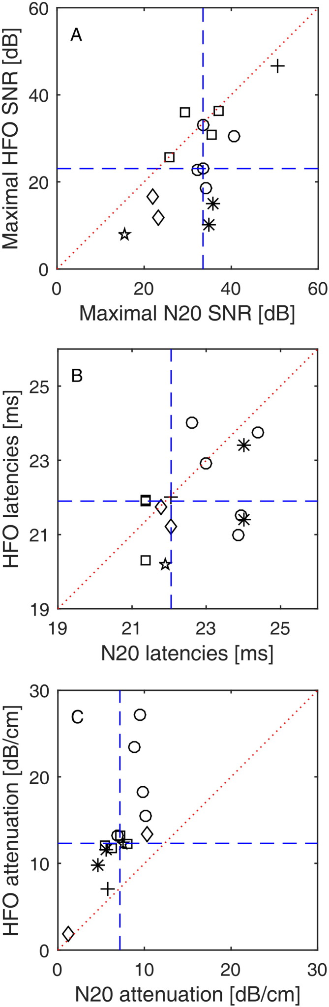
N20 and HFO characteristics across six patients.
(A) Scatter plot for N20 vs. HFO SNR at channels with the maximal N20-HFO response (dashed blue lines: medians, dotted red line: main diagonal). The N20 had higher maximal SNR (32.2 ± 8.3 dB, median 33.5 dB) than the HFO (23.7 ± 11.8 dB, median 23 dB). The six different markers denote recordings from the six patients. Measurements in individual patients, which had been repeated at different cortical sites, appear as clusters in the plot.
(B) Scatter plot for N20 vs. HFO latencies at channels with the maximal N20-HFO response. The N20 had median latency 22.1 ms (22.6 ± 1.2 ms) and the HFO had median latency 21.9 ms (21.9 ± 1.1 ms).
(C) Scatter plot for N20 vs. HFO attenuations of SNRs (dashed lines: medians, dotted line: main diagonal). The N20 SNR attenuates with a larger spatial extent (attenuation 7.2 ± 2.5 dB/cm, median 7.2) than the HFO SNR (13.5 ± 6.1 dB/cm, median 12.3).
The N20 had median latency 22.1 ms (22.6 ± 1.2 ms), while the HFO had median latency 21.9 ms (21.9 ± 1.1 ms) (Fig. 2B). The HFO preceded the N20 peak in 11 of 15 cases, which was found to be a statistical trend (N = 15 recordings, p = 0.062).
The SNR of the N20 attenuated with a larger spatial extent (median 7.2 dB/cm, mean 7.2 ± 2.5 dB/cm) than the SNR of the HFO (median 12.3 dB/cm, mean 13.5 ± 6.1 dB/cm) (Fig. 2C). The difference was statistically significant (N = 15 recordings, p < 0.001). Recordings in individual patients, repeated at different cortical sites, appear as clusters in the plots (Fig. 2A–C). Over six patients, the difference was statistically significant (sign test p = 0.031). We also found significant correlations between the SNR of N20 and HFO (rho = 0.58, p = 0.025) and the attenuation of N20 and HFO (rho = 0.86, p < 0.001).
The maximum of N20 and HFO appeared in the same electrode contact in 13/15 recordings. Visual inspection revealed a phase reversal for the N20 in 14/15 recordings and in 10/15 recordings for the HFO.
3.3. N20 and HFO dampening across the skull
Across all 15 ECoG recordings, we additionally recorded scalp EEG in 10 recordings (five patients). Scalp HFOs were found in 3/10 recordings in three patients. As an example, Fig. 3A (blue trace, patient 2) shows the scalp HFO clearly distinguishable from background noise, while in the red trace (patient 6) the HFO was masked by noise. The corresponding cortical HFOs are shown in Fig. 3B. We selected one representative recording for each of the five patients and reported SNR in scalp EEG and ECoG in Fig. 3C and D, respectively.
Fig. 3.

Simultaneous scalp EEG and ECoG recording.
(A) Scalp EEG (> 500 Hz). The HFO recorded in patient 2 (blue) has visible oscillations at around 20 ms after the stimulus. The HFO recorded in patient 6 (red) is masked by the noise.
(B) ECoG (> 500 Hz). HFOs recorded from patient 2 (blue) and patient 6 (red) have visible oscillations at around 20 ms after the stimulus. Note the difference in scale between scalp EEG and ECoG.
(C) SNR in scalp EEG. In 3 of 5 patients, SNR exceeded the noise level (SNR = 1 black line).
(D) SNR in ECoG for the optimal recording of each patient.
The N20 amplitude in the scalp EEG (median 1.8 μV, range 1.3–2.4 μV) was smaller than in the ECoG (median 11.6 μV, range 3.2–69 μV), leading to a median dampening factor δN20 = 6 (range 2–49). Similarly, the HFO amplitude in the scalp EEG (median 73 nV, range 51–203 nV) was smaller than in the ECoG (median 1474 nV, range 455–13910 nV) leading to a median dampening factor δHFO = 17 (range 8–103). N20 and HFO dampening factors were highly correlated across subjects (rho = 0.99, p = 0.010). The wide range of variation can be explained by the spatial variability of both subdural strip and scalp EEG placement with respect to the source.
The noise level found in scalp EEG (70 ± 23 nV) and ECoG (106 ± 44 nV) did not differ significantly (p = 0.177). This allowed us to describe the detectability in terms of SNR, as depicted in Fig. 3C and D. In the case of patient 2, the HFO is clearly distinguishable at the scalp. In patients 1 and 3, the HFO is at the edge of detectability (SNR > 1.5). In the last two cases, the cortical source had an amplitude fairly below 1 μV pp (see patients 5 and 6, Table 2), which, considering a dampening factor of 17 and scalp noise of 52 and 97 nV pp, resulted in a scalp SNR below 1.5. Thus, the HFO in the scalp EEG remained buried into noise.
Table 2.
Scalp EEG and ECoG recording.
| Patient | Amplitude EEG pp [nV] | Noise EEG SD [nV] | SNR EEG | Amplitude ECoG pp [nV] | Noise ECoG SD [nV] | SNR ECoG |
|---|---|---|---|---|---|---|
| 1 | 140 | 12 | 1.7 | 13910 | 10 | 192.9 |
| 2 | 203 | 11 | 2.6 | 4278 | 15 | 40.7 |
| 3 | – | – | – | 2344 | 11 | 31.9 |
| 4 | 65 | 6 | 1.5 | 455 | 12 | 5.3 |
| 5 | 51 | 7 | 1.0 | 529 | 16 | 4.8 |
| 6 | 73 | 14 | 0.8 | 603 | 27 | 3.2 |
3.4. The spatial attenuation as an estimator of the noise level and the cortical area contributing to scalp EEG
In order to understand the meaning of different spatial attenuation for different spectral components, we investigated the relation between the attenuation values and the corresponding noise level and the extent of cortical area where SNR > 1.
We explained the higher attenuation at the higher frequency in terms of the lower SNR (Fig. 4A, for computational details see Section 2.11). As a starting point, we reproduced the real N20 data (Patient 3, Fig. 1F) by the red trace in Fig. 4A. We then simulated scenarios with decreasing SNR (Fig. 4A, other traces). The attenuation of the fitting function was highly correlated to the simulated SNR and, more importantly, to the cortical area where SNR > 1 (Fig. 4B).
Fig. 4.

Simulated scenario relating spatial attenuation and SNR.
(A) We simulated an electrode strip on cortex covering a distance of 5 cm with 51 equally spaced contacts and added Gaussian white noise with zero mean and standard deviation 1. We varied the SNR from 11 to 47. For each SNR we fitted a decay constant τ. SNR and τ correlated significantly (rho = − 0.92, p = 0.004).
(B) We determined the distance at which the exponential fit reached the noise level (SNR = 1) and calculated the cortical area of the circular disc with SNR > 1. The cortical area depended strongly on the attenuation τ (rho = − 0.91, p = 0.003).
In order to evaluate the correct estimation of the contributing area to the scalp EEG, we inserted our mean values for peak amplitude AECoG and spatial attenuation τ for N20 and HFO into Eq. (1). We computed the amplitude ratio between N20 and HFO for the scalp EEG estimated by the model and for the scalp EEG recorded in patients (Fig. 5). We observed a significant correlation (rho = 0.65, p = 0.049) across the 10 scalp EEG recordings.
Fig. 5.

Comparing estimated and recorded N20/HFO amplitude ratios in EEG.
We estimated the scalp EEG amplitude from the attenuation τ using formula [1]. Across the group of 10 EEG recordings, estimated and recorded ratios are significantly correlated (rho = 0.65, p = 0.049).
4. Discussion
We have shown that the detection of the evoked HFO in the ECoG recordings is feasible under propofol anesthesia during surgery, complementing scalp EEG studies, which reported vanishing evoked HFO under propofol anesthesia (Klostermann et al., 2000).
We characterized the spatial attenuation of N20 and HFO components along the subdural contacts, expressed in terms of the SNR. The issue of the extension of the cortical area contributing to the scalp EEG is of great interest in order to define the detectability of pathologic components, i.e. epilepsy related HFOs (Andrade-Valenca et al., 2011, Kobayashi et al., 2010).
Here we provided the analysis of a simplified scenario, investigating physiological components of N20 and HFO with well-defined spatio-temporal properties. The precise timing given by the response phase-locked to the stimulus onset allows decreasing the noise level by a factor of 30–60 through averaging. In this setup we can explore the detectability of the HFO.
4.1. N20 and HFO dampening from cortex to scalp
To our knowledge, this is the first study reporting simultaneous invasive and non-invasive SEP recordings in humans. A cortical HFO with amplitude 2–13 μV pp was detectable in the scalp EEG, if the scalp EEG noise did not exceed the range 70–100 nV pp. The HFO amplitude decreased from ECoG to scalp EEG by a median factor of 17. This is in agreement with computational models (Telenczuk et al., 2015) and experimental evidence (Shimazu et al., 2000), which have shown a dampening factor from epidural to scalp level in the range of 10 to 100 in monkeys. In our surgical setting, skull opening could in principle increase the scalp EEG amplitude (Lau et al., 2014, von Ellenrieder et al., 2014a), which was however not observed in our patient group. We may safely assume that the sources of N20 and HFO are strictly co-localized (Ozaki and Hashimoto, 2011). The dampening factor across the skull reported here might be affected by a suboptimal strip and/or scalp electrode placement due to the surgical constraints. Nevertheless, the ratio of dampening factors δN20/δHFO = 0.6 (range 0.5–0.7) was highly stable across patients. We would have expected a ratio δN20/δHFO ~ 1, because the conductivity across the skull is constant over frequency (Oostendorp et al., 2000). The reduced ratio must be explained by the volume of cortical tissue contributing to the detected component on the scalp. We will further explore the issue of detectability in Section 4.3 based on the evidence coming from the cortical spatial attenuation of SNR along the strip.
4.2. HFO amplitude reduction due to propofol anesthesia
In our study, we show the presence of the HFOs under propofol anesthesia in intraoperative recordings both in the ECoG and the scalp EEG. Our amplitude of 1.7 ± 1.4 μV pp on the ECoG is lower than the physiological HFO amplitude of 5–10 μV pp observed in awake patients (Kojima et al., 2001, Maegaki et al., 2000). We attribute this reduction to the propofol anesthesia. The reduction observed by (Klostermann et al., 2000) in scalp EEG is in a similar order of magnitude, considering that they had scalp HFO of around 200 nV pp on top of a noise level of about 50 nV pp. With propofol, their scalp HFO was reduced to < 50 nV pp, which is below the noise level, i.e. not detectable.
By co-recording scalp EEG and ECoG, we present here cases where the scalp HFO amplitudes were below and above noise level. In particular, for a noise level of 80 nV pp in the scalp EEG and a dampening factor of 20, we observed that an ECoG HFO amplitude of at least 1.6 μV is required in order to project cortical HFO on the scalp above noise level (noise level around 50 nV, minimum ECoG HFO amplitude of 1 μV in (Klostermann et al., 2000)). We observed 5/10 recordings where this is verified by the ECoG and by the corresponding scalp EEG. In the other 5 cases, the source, recorded from the cortex, exhibited an amplitude lower than 1.6 μV pp and did not produce a detectable contribution in the scalp EEG.
4.3. Spatial attenuation of N20 and HFO in ECoG
We characterized the detectability of N20 and HFO in the ECoG by sampling their attenuation over strip electrode contacts. The field of the dipoles propagates through the tissue by volume conduction. Compared to the N20, the HFO signal shows a steeper exponential decrease until it converges to noise level (Figs. 1F–G, 2C). This is not due to the higher frequency of the HFO signal, since experimental (Bedard and Destexhe, 2009, Bedard et al., 2010, Gabriel et al., 2009, Wagner et al., 2014) and computational studies (Bedard and Destexhe, 2009, Bedard et al., 2010) indicate that the tissue conductivity is constant in our frequency range of interest (100–1000 Hz). We explain the higher attenuation at the higher frequency in terms of the lower SNR and put the noise level in relation to the extent of detectable source in the ECoG (Fig. 4). Since this area directly contributes to the projection over the scalp (Tao et al., 2007, Yamazaki et al., 2012), the attenuation is therefore an estimator of source detectability from scalp EEG.
The spatial attenuation to noise level was proportional to the area contributing to the scalp EEG for both N20 and HFO. This explains the different dampening observed across the skull from ECoG to scalp EEG. The median values of spatial attenuation for τN20 = 7 dB/cm and τHFO = 12 dB/cm have the ratio τN20/τHFO = 0.6. This is compatible with the ratio δN20/δHFO = 0.6 observed between N20 and HFO dampening factors (Section 4.1). Taken together, the SNR characterized for the ECoG quantified the detectability of a signal in the scalp EEG (Fig. 5).
Specifically in the case of the HFO frequency range, the noise in the scalp EEG has been shown to be rather technical than biological (Scheer et al., 2006). Further investigation has quantified the criticality of the noise reduction (Waterstraat et al., 2012), and the combination of optimized hardware and tailored de-noising technique have been shown to maximally improve the SNR (Waterstraat et al., 2015a, Waterstraat et al., 2015b). Quantifying the HFO detectability in a well-defined case is the basis for a generalized investigation of the detectability of a signal under critical SNR conditions.
4.4. Limitations of the study
The SEP HFO consists of pre- and post-synaptic components (Curio, 2000, Ozaki and Hashimoto, 2011) and it has been shown that the stimulation rate affects the post-synaptic component as recorded by ECoG (Urasaki et al., 2002) and scalp EEG (Klostermann et al., 1999). We collected and analyzed recordings with different stimulation rates ranging from 0.7 to 12.7 Hz and did not address the variability induced by the stimulation rate. We rather tested the possibility to obtain high SNR in simultaneous ECoG and scalp EEG recordings. In this context, the finding of a robust HFO at 12.7 Hz stimulation rate is an interesting result in itself. In comparison to (Urasaki et al., 2002), we used a much higher number of averages (10000 vs. 1000), which improved the SNR by a factor of 3. This may explain why we obtained a robust HFO even at high stimulation rate.
A further limitation of the current dataset is the heterogeneity of the electrode placement due to surgical restrictions. Nevertheless, since the electrode sites are the same for both N20 and HFO, the ratio of N20 and HFO propagation is preserved. Hence, the ratio between scalp N20 and HFO correlates with the ratio computed by the model expressed by Eq. (1).
4.5. Implications for the detection of pathological HFOs
Pathological HFOs (pHFOs, 80–500 Hz) have been suggested as biomarkers to identify epileptogenic tissue (Bragin et al., 2010, Jacobs et al., 2012, Zijlmans et al., 2012). Such pHFOs were found in the epileptic rat brain to be generated by a pinpoint generator of less than 1 mm3 (Bragin et al., 2002). Because of the small number of neurons that are synchronously active in this pinpoint generator, the detectability of pathological HFOs is still a major challenge. For these HFOs to be detectable in scalp EEG, some authors require the source to extend for at least 5–10 cm2 of cortex (Tao et al., 2007, Yamazaki et al., 2012), while other authors propose also smaller sources (von Ellenrieder et al., 2014a, Zelmann et al., 2014).
The spatial attenuation of the SNR, which we present here for an HFO model system, could provide a more detailed characterization of the detectability of spontaneous HFOs. Since our quantitative findings demonstrate that noise limits the detection of evoked responses, low noise is certainly critical for spontaneous HFO recording. Noise reduction may be achieved by implementing low-noise recording technology (Fedele et al., 2015, Scheer et al., 2011), which may in turn facilitate fast automatic detection of spontaneous HFOs (Burnos et al., 2014).
5. Conclusions
The detection of evoked HFOs in simultaneous subdural and scalp recordings was found possible under propofol anesthesia during surgery.
In the ECoG, the HFO amplitude attenuated to noise level over a smaller spatial scale than the N20 amplitude. The spatial attenuation along subdural contacts represented a good estimation of the area contributing to scalp EEG.
In terms of detectability, we described the role of the noise level, which was more critical for the HFO than for the N20. The results obtained in this context are not limited to SEP HFO, but may be generalized to biological signals in the same SNR range.
6. Acknowledgments
We thank Vontobel Stiftung and Swiss National Science Foundation for funding (SNF 320030_156029).
7. Disclosure
The authors report no conflict of interest concerning the materials or methods used in this study or the findings specified in this paper.
References
- Andrade-Valenca L.P., Dubeau F., Mari F., Zelmann R., Gotman J. Interictal scalp fast oscillations as a marker of the seizure onset zone. Neurology. 2011;77:524–531. doi: 10.1212/WNL.0b013e318228bee2. [DOI] [PMC free article] [PubMed] [Google Scholar]
- Bedard C., Destexhe A. Macroscopic models of local field potentials and the apparent 1/f noise in brain activity. Biophys. J. 2009;96:2589–2603. doi: 10.1016/j.bpj.2008.12.3951. [DOI] [PMC free article] [PubMed] [Google Scholar]
- Bedard C., Rodrigues S., Roy N., Contreras D., Destexhe A. Evidence for frequency-dependent extracellular impedance from the transfer function between extracellular and intracellular potentials: intracellular-LFP transfer function. J. Comput. Neurosci. 2010;29:389–403. doi: 10.1007/s10827-010-0250-7. [DOI] [PubMed] [Google Scholar]
- Bragin A., Mody I., Wilson C.L., Engel J., Jr. Local generation of fast ripples in epileptic brain. J. Neurosci. 2002;22:2012–2021. doi: 10.1523/JNEUROSCI.22-05-02012.2002. [DOI] [PMC free article] [PubMed] [Google Scholar]
- Bragin A., Engel J., Jr., Staba R.J. High-frequency oscillations in epileptic brain. Curr. Opin. Neurol. 2010;23:151–156. doi: 10.1097/WCO.0b013e3283373ac8. [DOI] [PMC free article] [PubMed] [Google Scholar]
- Burnos S., Hilfiker P., Surucu O., Scholkmann F., Krayenbuhl N., Grunwald T., Sarnthein J. Human intracranial high frequency oscillations (HFOs) detected by automatic time-frequency analysis. PLoS One. 2014;9 doi: 10.1371/journal.pone.0094381. [DOI] [PMC free article] [PubMed] [Google Scholar]
- Cracco R.Q., Cracco J.B. Somatosensory evoked potential in man: far field potentials. Electroencephalogr. Clin. Neurophysiol. 1976;41:460–466. doi: 10.1016/0013-4694(76)90057-2. [DOI] [PubMed] [Google Scholar]
- Curio G. Linking 600-Hz “spikelike” EEG/MEG wavelets (“sigma-bursts”) to cellular substrates: concepts and caveats. J. Clin. Neurophysiol. 2000;17:377–396. doi: 10.1097/00004691-200007000-00004. [DOI] [PubMed] [Google Scholar]
- Curio G., Mackert B.M., Burghoff M., Koetitz R., Abraham-Fuchs K., Harer W. Localization of evoked neuromagnetic 600 Hz activity in the cerebral somatosensory system. Electroencephalogr. Clin. Neurophysiol. 1994;91:483–487. doi: 10.1016/0013-4694(94)90169-4. [DOI] [PubMed] [Google Scholar]
- Fedele T., Scheer H.J., Burghoff M., Curio G., Korber R. Ultra-low-noise EEG/MEG systems enable bimodal non-invasive detection of spike-like human somatosensory evoked responses at 1 kHz. Physiol. Meas. 2015;36:357–368. doi: 10.1088/0967-3334/36/2/357. [DOI] [PubMed] [Google Scholar]
- Gabriel C., Peyman A., Grant E.H. Electrical conductivity of tissue at frequencies below 1 MHz. Phys. Med. Biol. 2009;54:4863–4878. doi: 10.1088/0031-9155/54/16/002. [DOI] [PubMed] [Google Scholar]
- Gregorie E.M., Goldring S. Localization of function in the excision of lesions from the sensorimotor region. J. Neurosurg. 1984;61:1047–1054. doi: 10.3171/jns.1984.61.6.1047. [DOI] [PubMed] [Google Scholar]
- Jacobs J., Staba R., Asano E., Otsubo H., Wu J.Y., Zijlmans M., Mohamed I., Kahane P., Dubeau F., Navarro V., Gotman J. High-frequency oscillations (HFOs) in clinical epilepsy. Prog. Neurobiol. 2012;98:302–315. doi: 10.1016/j.pneurobio.2012.03.001. [DOI] [PMC free article] [PubMed] [Google Scholar]
- Klostermann F., Nolte G., Curio G. Multiple generators of 600 Hz wavelets in human SEP unmasked by varying stimulus rates. Neuroreport. 1999;10:1625–1629. doi: 10.1097/00001756-199906030-00001. [DOI] [PubMed] [Google Scholar]
- Klostermann F., Funk T., Vesper J., Siedenberg R., Curio G. Propofol narcosis dissociates human intrathalamic and cortical high-frequency (> 400 Hz) SEP components. Neuroreport. 2000;11:2607–2610. doi: 10.1097/00001756-200008030-00051. [DOI] [PubMed] [Google Scholar]
- Kobayashi K., Watanabe Y., Inoue T., Oka M., Yoshinaga H., Ohtsuka Y. Scalp-recorded high-frequency oscillations in childhood sleep-induced electrical status epilepticus. Epilepsia. 2010;51:2190–2194. doi: 10.1111/j.1528-1167.2010.02565.x. [DOI] [PubMed] [Google Scholar]
- Kojima Y., Uozumi T., Akamatsu N., Matsunaga K., Urasaki E., Tsuji S. Somatosensory evoked high frequency oscillations recorded from subdural electrodes. Clin. Neurophysiol. 2001;112:2261–2264. doi: 10.1016/s1388-2457(01)00695-2. [DOI] [PubMed] [Google Scholar]
- Lau S., Flemming L., Haueisen J. Magnetoencephalography signals are influenced by skull defects. Clin. Neurophysiol. 2014;125:1653–1662. doi: 10.1016/j.clinph.2013.12.099. [DOI] [PubMed] [Google Scholar]
- Lüders H., Lesser R.P., Hahn J., Dinner D.S., Klem G. Cortical somatosensory evoked potentials in response to hand stimulation. J. Neurosurg. 1983;58:885–894. doi: 10.3171/jns.1983.58.6.0885. [DOI] [PubMed] [Google Scholar]
- Maegaki Y., Najm I., Terada K., Morris H.H., Bingaman W.E., Kohaya N., Takenobu A., Kadonaga Y., Luders H.O. Somatosensory evoked high-frequency oscillations recorded directly from the human cerebral cortex. Clin. Neurophysiol. 2000;111:1916–1926. doi: 10.1016/s1388-2457(00)00449-1. [DOI] [PubMed] [Google Scholar]
- Oostendorp T.F., Delbeke J., Stegeman D.F. The conductivity of the human skull: results of in vivo and in vitro measurements. IEEE Trans. Biomed. Eng. 2000;47:1487–1492. doi: 10.1109/TBME.2000.880100. [DOI] [PubMed] [Google Scholar]
- Ozaki I., Hashimoto I. Exploring the physiology and function of high-frequency oscillations (HFOs) from the somatosensory cortex. Clin. Neurophysiol. 2011;122:1908–1923. doi: 10.1016/j.clinph.2011.05.023. [DOI] [PubMed] [Google Scholar]
- Sakura Y., Terada K., Usui K., Baba K., Usui N., Umeoka S., Yamaguchi M., Matsuda K., Tottori T., Mihara T., Nakamura F., Inoue Y. Very high-frequency oscillations (over 1000 Hz) of somatosensory-evoked potentials directly recorded from the human brain. J. Clin. Neurophysiol. 2009;26:414–421. doi: 10.1097/WNP.0b013e3181c298c9. [DOI] [PubMed] [Google Scholar]
- Scheer H.J., Sander T., Trahms L. The influence of amplifier, interface and biological noise on signal quality in high-resolution EEG recordings. Physiol. Meas. 2006;27:109–117. doi: 10.1088/0967-3334/27/2/002. [DOI] [PubMed] [Google Scholar]
- Scheer H.J., Fedele T., Curio G., Burghoff M. Extension of non-invasive EEG into the kHz range for evoked thalamocortical activity by means of very low noise amplifiers. Physiol. Meas. 2011;32:N73–N79. doi: 10.1088/0967-3334/32/12/N02. [DOI] [PubMed] [Google Scholar]
- Shimazu H., Kaji R., Tsujimoto T., Kohara N., Ikeda A., Kimura J., Shibasaki H. High-frequency SEP components generated in the somatosensory cortex of the monkey. Neuroreport. 2000;11:2821–2826. doi: 10.1097/00001756-200008210-00042. [DOI] [PubMed] [Google Scholar]
- Stockwell R.G., Mansinha L., Lowe R.P. Localization of the complex spectrum: the S transform. IEEE Trans. Signal Process. 1996;44:998–1001. [Google Scholar]
- Tao J.X., Baldwin M., Ray A., Hawes-Ebersole S., Ebersole J.S. The impact of cerebral source area and synchrony on recording scalp electroencephalography ictal patterns. Epilepsia. 2007;48:2167–2176. doi: 10.1111/j.1528-1167.2007.01224.x. [DOI] [PubMed] [Google Scholar]
- Telenczuk B., Baker S.N., Kempter R., Curio G. Correlates of a single cortical action potential in the epidural EEG. Neuroimage. 2015;109:357–367. doi: 10.1016/j.neuroimage.2014.12.057. [DOI] [PMC free article] [PubMed] [Google Scholar]
- Urasaki E., Genmoto T., Akamatsu N., Wada S., Yokota A. The effects of stimulus rates on high frequency oscillations of median nerve somatosensory-evoked potentials—direct recording study from the human cerebral cortex. Clin. Neurophysiol. 2002;113:1794–1797. doi: 10.1016/s1388-2457(02)00291-2. [DOI] [PubMed] [Google Scholar]
- von Ellenrieder N., Beltrachini L., Muravchik C.H., Gotman J. Extent of cortical generators visible on the scalp: effect of a subdural grid. Neuroimage. 2014;101:787–795. doi: 10.1016/j.neuroimage.2014.08.009. [DOI] [PubMed] [Google Scholar]
- von Ellenrieder N., Beltrachini L., Perucca P., Gotman J. Size of cortical generators of epileptic interictal events and visibility on scalp EEG. Neuroimage. 2014;94:47–54. doi: 10.1016/j.neuroimage.2014.02.032. [DOI] [PubMed] [Google Scholar]
- Wagner T., Eden U., Rushmore J., Russo C.J., Dipietro L., Fregni F., Simon S., Rotman S., Pitskel N.B., Ramos-Estebanez C., Pascual-Leone A., Grodzinsky A.J., Zahn M., Valero-Cabre A. Impact of brain tissue filtering on neurostimulation fields: a modeling study. Neuroimage. 2014;85(Pt 3):1048–1057. doi: 10.1016/j.neuroimage.2013.06.079. [DOI] [PMC free article] [PubMed] [Google Scholar]
- Waterstraat G., Telenczuk B., Burghoff M., Fedele T., Scheer H.J., Curio G. Are high-frequency (600 Hz) oscillations in human somatosensory evoked potentials due to phase-resetting phenomena? Clin. Neurophysiol. 2012;123:2064–2073. doi: 10.1016/j.clinph.2012.03.013. [DOI] [PubMed] [Google Scholar]
- Waterstraat G., Fedele T., Burghoff M., Scheer H.-J., Curio G. Recording human cortical population spikes non-invasively — an EEG tutorial. J. Neurosci. Methods. 2015;250:74–84. doi: 10.1016/j.jneumeth.2014.08.013. [DOI] [PubMed] [Google Scholar]
- Waterstraat G., Burghoff M., Fedele T., Nikulin V., Scheer H.J., Curio G. Non-invasive single-trial EEG detection of evoked human neocortical population spikes. Neuroimage. 2015;105:13–20. doi: 10.1016/j.neuroimage.2014.10.024. [DOI] [PubMed] [Google Scholar]
- Yamazaki M., Tucker D.M., Fujimoto A., Yamazoe T., Okanishi T., Yokota T., Enoki H., Yamamoto T. Comparison of dense array EEG with simultaneous intracranial EEG for interictal spike detection and localization. Epilepsy Res. 2012;98:166–173. doi: 10.1016/j.eplepsyres.2011.09.007. [DOI] [PubMed] [Google Scholar]
- Zelmann R., Lina J.M., Schulze-Bonhage A., Gotman J., Jacobs J. Scalp EEG is not a blur: it can see high frequency oscillations although their generators are small. Brain Topogr. 2014;27:683–704. doi: 10.1007/s10548-013-0321-y. [DOI] [PubMed] [Google Scholar]
- Zijlmans M., Jiruska P., Zelmann R., Leijten F.S., Jefferys J.G., Gotman J. High-frequency oscillations as a new biomarker in epilepsy. Ann. Neurol. 2012;71:169–178. doi: 10.1002/ana.22548. [DOI] [PMC free article] [PubMed] [Google Scholar]