
Figure E6. Examples of RGC groups.
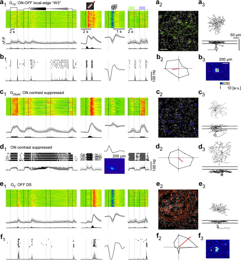
a, functional “fingerprint” of G10 RGCs, identified as local-edge-detector (W3) cells. Light-evoked Ca2+ responses of n=149 cells (a1): heat maps (top) illustrating individual responses, with response averages and firing rates estimated from Ca2+ signals (cf. Fig. E1a–d) below. Ganglion cell layer (a2; experiment from Fig. 1a2) with G10 somata (green) and receptive fields (RFs, dotted) indicated. Grey circles mark cells with RFs that passed a quality criterion (Methods). Example morphology of a G10 cell filled after electrical single-cell recording (a3, cf. b). For a complete summary of the group’s properties, see SI Data 210. b, electrical single-cell recording of a G10 cell: spiking responses as raster plots and mean spike rates for “chirp”, moving bar and blue/green stimuli as well as time kernel derived from noise stimulus (b1), polar plot of responses to moving bar (b2) and RF map (b3) c1,2, G28a,b (n=100) contrast-suppressed ON RGCs with sample morphology (c3; G28a,b cell dye-injected after Ca2+ imaging). d1,2, electrical single-cell recording of a contrast-suppressed ON RGC with different morphology (d3 vs. c3). e,f, G2 direction-selective OFF RGCs (n=162) that stratify between the ChAT bands (e3), as fingerprint (e1,2) and exemplary electrical single-cell recording (f1–3). Scale bars: 50 μm; grey lines in a3,c3,d3,e3: ChAT bands.