A bidirectional freezing method to assemble ceramic particles into porous nacre-like scaffolds aligned over centimeter-scales.
Keywords: Biomimetic, ceramic scaffolds, nacre, freeze casting, ice nucleation
Abstract
Natural materials, such as bone, teeth, shells, and wood, exhibit outstanding properties despite being porous and made of weak constituents. Frequently, they represent a source of inspiration to design strong, tough, and lightweight materials. Although many techniques have been introduced to create such structures, a long-range order of the porosity as well as a precise control of the final architecture remain difficult to achieve. These limitations severely hinder the scale-up fabrication of layered structures aimed for larger applications. We report on a bidirectional freezing technique to successfully assemble ceramic particles into scaffolds with large-scale aligned, lamellar, porous, nacre-like structure and long-range order at the centimeter scale. This is achieved by modifying the cold finger with a polydimethylsiloxane (PDMS) wedge to control the nucleation and growth of ice crystals under dual temperature gradients. Our approach could provide an effective way of manufacturing novel bioinspired structural materials, in particular advanced materials such as composites, where a higher level of control over the structure is required.
INTRODUCTION
Natural materials, such as bone, teeth, shells, and wood, show outstanding properties despite being porous and made of weak constituents (1). The secret usually lies in their sophisticated hierarchical architecture ranging from nano/microscopic to macroscopic levels (2–5). Such architectures have been perfected over the past billions of years, resulting in wonderful materials that are very often strong, tough, and lightweight and serve as a source of inspiration for every materials designer. Porous ceramic structures, in particular, are desirable for a wide range of applications in areas such as supported catalysis (6), scaffolds for tissue engineering (7, 8), foams (9), fuel cell electrodes (10), filters for water purification (6), and many others (11). Multiple techniques (12, 13), such as replica, direct foaming, or sacrificial templating, have been developed to manufacture such scaffolds. Most recently, three-dimensional (3D) printing (14) has also been used as an alternative technique. However, these techniques have several limitations because they are often time-consuming or size-limiting processes, not environmentally friendly, too costly, or just do not allow precise control over the final structure. An ideal strategy for engineering pores into materials in a more controllable way and at a larger scale has yet to be developed.
Freeze casting can overcome many of these previous limitations (15). This very promising technique enables assembly of ceramic particles into scaffolds that have a highly aligned 3D porous network. The technique uses lamellar ice crystals as a template to assemble building blocks for making biomimetic scaffolds or composites (16–18). It offers the advantage of being applicable to a wide spectrum of materials [such as ceramics (16–18) and/or polymers (19)], having various shapes [that is, particles (16, 17, 19), nanowires (20), and ceramic platelets (18, 21) or graphene sheets (22)]. In addition, the technique is environmentally friendly, with water usually being used as the solvent. Finally, easy control of the structural features at multiple length scales is achievable by modifying ice crystal morphology with additives and/or the cooling rate (23–26).
Nevertheless, in the case of conventional freeze casting (also referred to as “ice templating” or “unidirectional freezing”), the slurry starts freezing under a single temperature gradient, causing the nucleation of ice to occur randomly on the cold finger surface. As a result, multiple small-size (submillimeter scale) domains, that is, various ice crystal orientations in the plane perpendicular to the freezing direction, are observed (27). Despite a pressing demand for the development of new processing techniques that can build large-scale porous aligned lamellar structures, this limitation severely hinders the scale-up fabrication of layered structures aimed for larger applications.
Here, we report on a new bidirectional freezing technique which can assemble small building blocks (ceramic particles, platelets, and/or polymer) into a large-size single-domain (centimeter-scale) porous lamellar structure comparable to natural nacre, albeit without the “mortar.” This was achieved through a proper control of nucleation of ice crystals and growth under dual temperature gradients generated by covering the cold finger with a polydimethylsiloxane (PDMS) wedge having different slopes. (To illustrate the breakup of the gradient into vertical and horizontal components during freezing, we use in this paper the expression “dual temperature gradients,” although the resulting combined temperature gradient is actually singular. This allows the ice to grow both vertically and horizontally, which is critical for obtaining large-scale aligned lamellar structures.) Although hydroxyapatite (HA) was used as a proof of concept to study the bidirectional freezing mechanism in detail, this technique can also be applied to any other ceramic or polymeric materials of any shape. Our approach could provide an effective way of designing and manufacturing novel, bioinspired, structural materials, in particular advanced materials, such as composites, where a higher level of control over the structure is required.
RESULTS
Comparison between conventional and bidirectional freeze-casting methods
Figure 1 shows a comparison between unidirectional and bidirectional freeze-casting techniques and their corresponding lamellar structures. In both cases, the same slurry with 20 volume % of HA particles dispersed in water was used. For the conventional unidirectional freeze-casting technique, the slurry was poured into a Teflon mold that was placed directly in contact with the cold finger (copper plate) (Fig. 1A). When the cold finger temperature decreased, a single vertical temperature gradient (ΔTV) was created, forcing ice crystals to grow preferentially from the bottom to the top (Fig. 1B). However, because the nucleation of ice crystals occurred randomly all over the cold finger surface, that is, nucleation in 2D, the final structure revealed multiple submillimeter domains corresponding to various orientations of ice crystals. These domains could be easily observed in the horizontal cross section of the HA scaffold, as shown by the scanning electron microscopy (SEM) image (Fig. 1C). Although the approach of a patterned cold finger (27) and “freezing under flow” (26) have been previously applied to further manipulate the orientation of the ice crystals, it turned out that only a limited extent of alignment (2 or 4 mm) was obtained in the plane parallel to the cold finger.
Fig. 1. Scheme of both conventional and bidirectional freezing techniques and resulting scaffolds.
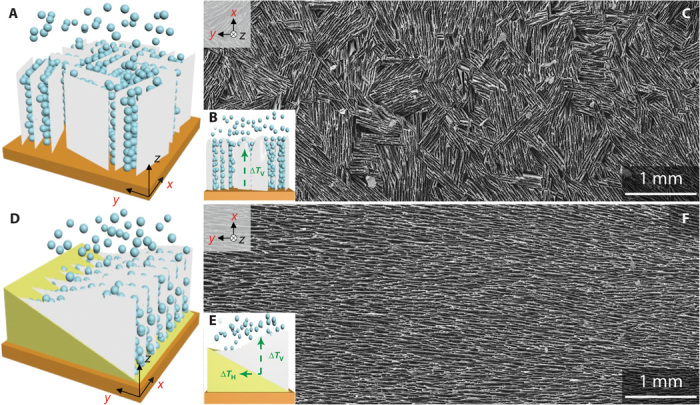
(A to F) Comparison between conventional (A and B) and newly developed bidirectional freeze-casting techniques (D and E), and resulting HA scaffolds with small-scale (multiple-domain) (C) and large-scale (single-domain) lamellar structures (F). (A and B) In the conventional freeze-casting technique, a single vertical temperature gradient (ΔTV) is used. The nucleation occurs simultaneously all over the copper substrate, and a horizontal ice profile is obtained. (C) This results in a short-range lamellar structure that contains multiple domains of various orientations in the plane parallel to the copper substrate. (D) With bidirectional freeze casting, a PDMS wedge is placed in between the slurry and the copper substrate. (E) This generates a horizontal temperature gradient (ΔTH) in addition to the vertical gradient (ΔTV). As a result, a wavy ice-front profile is obtained. (F) A large-scale (several millimeters and limited here by the mold size) monodomain lamellar structure that aligns preferentially along the dual temperature gradients is observed in the cross section parallel to the copper substrate. Representative scaffolds shown in SEM images in (C) and (F) were prepared from a 20 volume % HA slurry and using a cooling rate of 5°C/min. For the vertical cross section, see figs. S2 and S3.
For our newly developed bidirectional freeze-casting technique, PDMS wedges with different slopes were used to isolate the cold finger from the slurry (Fig. 1D). On cooling, the bottom end of the wedge has a lower temperature than the top end. By proper adjustment of the cooling rate, two temperature gradients, that is, vertical (ΔTV) and horizontal (ΔTH), were generated at the same time (Fig. 1E). Under such conditions, the slurry started freezing in a gradient manner from the bottom to the top of the wedge with ice crystals nucleating only at the bottom end of the wedge, that is, “nucleation in 1D,” and growing preferentially in two directions: vertically away from the cold finger and horizontally along the PDMS wedge. As a result, after sublimating and sintering, a large-scale monodomain lamellar structure was obtained. From a horizontal cross section of HA scaffold, the long-range order is clearly apparent, as seen in the SEM image in Fig. 1F. The specimen size, as large as 25 mm (see fig. S1), is here limited only by the size of the mold. This demonstrates that bidirectional freeze casting can generate ordering in two directions, whereas unidirectional freeze casting is limited to only one direction (figs. S2 and S3). From the perspective of making high ceramic fraction composites, such large-scale aligned structures, after being pressed and infiltrated with a polymer, would be clearly superior to those obtained by conventional freeze casting (17).
Effect of slope angle and cooling rate on structural alignment
Because cooling rate greatly affects the freeze-cast structure (16, 24), our bidirectional freeze-casting experiments were performed at different cooling rates (1, 5, and 10°C/min) with various slope angles of PDMS wedges (0°, 5°, 10°, and 20°). Here, α = 0° represents a flat PDMS film with a thickness of ~1 mm. A 20 volume % HA slurry was used in all experiments. Scaffolds were then cut in the direction parallel to the cold finger, and the microstructure was observed with SEM (Fig. 2). Each domain, delimited by a given orientation, was labeled with artificial colors to be more easily distinguished (see figs. S4 and S5 for comparison between unprocessed and colored SEM images). Figure 2 shows that the domain orientations fluctuate significantly, depending on the experimental conditions, specifically, the cooling rate and the wedge angle. In the insets, Fourier transform images illustrate the global domain orientation over the whole cross section. At the lowest cooling rate of 1°C/min, no long-range alignment was observed regardless of the wedge angle (Fig. 2, A to D). At higher cooling rates (5 and 10°C/min), the alignment started to become more uniform when the PDMS wedge angle was increased from α = 0° to 20°, that is, domain sizes became larger and approached that of the whole sample size (Fig. 2, E to L). In other words, multiple domains were observed for α = 0° at both cooling rates of 5 and 10°C/min (Fig. 2, E and I), whereas the alignment was largely improved for α = 20° (Fig. 2, H and L). Eventually, under specific conditions (α = 20°, 5, or 10°C/min), a monodomain structure characterized by a single orientation across the whole sample, horizontally to the cold finger, was obtained.
Fig. 2. Domain orientations of HA scaffolds fabricated under different cooling rates (1, 5, and 10°C/min) and using PDMS wedges with various slope angles (α ≈ 0°, 5°, 10°, and 20°).
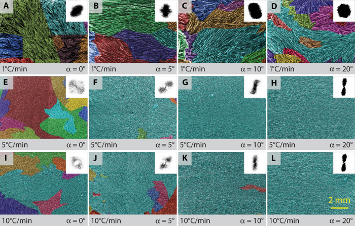
All the samples were prepared from a 20 volume % HA slurry. SEM images show the scaffold cross sections parallel to the cold finger. Each domain, delimited by a given orientation, was labeled with artificial colors. Insets: For every image, the Fourier transform indicates the alignment of global domains. (A to D) At the lowest cooling rate (1°C/min), no obvious large-scale aligned lamellar structure was observed regardless of the slope angle. (E to L) At higher cooling rates of 5 (E to H) and 10°C/min (I to L), domains appeared to become more aligned with increasing slope angle. For slope angles of 10° and 20°, a large single domain can be observed across the whole sample length.
Direct observation of ice profile propagation
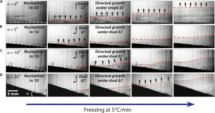
To further investigate the bidirectional freezing, and in particular the nucleation process, we recorded the ice-front propagation using a high-speed charge-coupled device (CCD) camera (Fig. 3). Every experiment was performed with the same 20 volume % HA slurry, at a fixed cooling rate of 5°C/min but with different slope angles: α = 0°, 5°, 10°, and 20°, as shown on the sequences of optical images in Fig. 3, A to D. The image sequences were taken at different time scales to compare the ice-front profile evolution in terms of shape but independently of the ice-front speed. In practice, the higher the cooling rate, the earlier the top of the wedge is reached by the ice front. Because α = 0° yields a single vertical temperature gradient, the slurry simultaneously nucleated all over the PDMS film (“nucleation in 2D”), generating a horizontally flat ice-front profile (Fig. 3A), which persisted throughout the freezing process. Slope angles of 5°, 10°, and 20° were able to generate two temperature gradients: vertical (ΔTV) and horizontal (ΔTH). Consequently, slurry solidification started at the bottom and then propagated to the top of the wedge (Fig. 3, B to D). The ice nucleation was initiated at the thinnest edge of the PDMS wedge (nucleation in 1D), in contrast to the nucleation in 2D when α = 0°. Once nucleation was completed, ice propagated not only vertically but also horizontally along the PDMS wedge (“directed growth under dual ΔT”), resulting in a wavy ice front profile. The shape of such an ice profile can be understood in several stages. At the beginning, because of the low PDMS thermal conductivity, ice only nucleates at the thinnest part of the wedge. At this stage, the supercooling effect makes the ice crystals promptly grow upward and along the PDMS wedge (23, 26). Gradually, the other part of the PDMS surface also becomes cold, which speeds up freezing along the PDMS surface. After the whole PDMS surface is frozen, ice crystals can only grow upward, limited by the mold. However, the ice-front profile became gradually flatter, indicating that the effect of PDMS wedge thickness becomes less obvious when ice is growing far enough from the cold finger (last column of Fig. 3). The effect of the cooling rate on ice-front profile during bidirectional freeze casting was also investigated using a PDMS wedge with an angle of α = 10° (fig. S6).
Fig. 3. Ice-profile propagation during bidirectional freeze casting using multiple slope angles.
(A) A uniform PDMS film (α = 0°) yields a single vertical temperature gradient. As a result, the slurry starts freezing over the entire surface (“nucleation in 2D” and “directed growth under single ΔT”). (B to D) Conversely, slope angles of α = 5°, 10°, and 20° generate dual temperature gradients (ΔTV and ΔTH), causing the slurry to freeze from the bottom to the top of the wedge surface (“nucleation in 1D” and “directed growth under dual ΔT”); this results in wavy ice profiles.
Evidence of unique ice nucleation and growth under dual temperature gradients
Scaffolds prepared by conventional and bidirectional freezing were cut vertically to the cold finger to observe and compare the differences in the ice nucleation and growth mechanisms. For conventional freeze casting, a disordered region is commonly observed at the bottom of the scaffold. This part, resulting from ice crystals that nucleate and quickly grow in the supercooled region close to the cold finger (23, 26), can be observed in Fig. 4, A and D. However, for bidirectional freezing, this disordered structure is only observed in the vicinity of the bottom of the wedge and indicates that the nucleation is now restricted to this zone (Fig. 4, B and E). It is noteworthy that the lamellar structure at this location is not aligned horizontally. When observing the middle cross section of a scaffold prepared by bidirectional freezing (Fig. 4, C and F), only a lamellar structure, well aligned horizontally along the wedge, can be observed. These observations indicate that the nucleation and growth mechanism are substantially different for conventional and bidirectional freezing, that is, “nucleation in 2D and directed growth under single ΔT” and “nucleation in 1D and directed growth under dual ΔT,” respectively.
Fig. 4. Representative SEM images of the xz cross sections perpendicular to the cold finger.
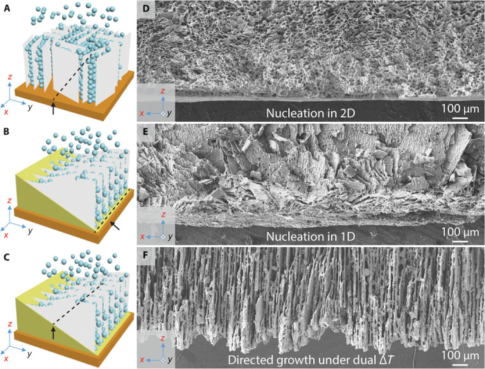
(A) In conventional freeze casting, nucleation takes place in 2D over an entire cold surface. The supercooling effect generates a disordered layer at the initial stage of freeze casting. (B and C) In bidirectional freeze casting, nucleation takes place in 1D along the line at the bottom of the wedge that is the closest to the cold finger. Different orientations of lamellar structure are observed. (C) As a result of the dual temperature gradients, ice crystals grow both vertically and horizontally along the wedge, generating well-aligned lamellar structure in the xz cross section perpendicular to the cold finger.
To further confirm the previous hypothesis, we used two thermocouples to record the slurry temperature in situ. The thermocouple probes were placed on opposite walls of the mold at positions (P1 and P2) corresponding to the height of the wedge, as illustrated on Fig. 5, A and B. TP1, TP2, and ΔTH (TP2 − TP1) are the temperatures at P1 and P2, respectively, and the horizontal temperature gradient. The schemes illustrate the setup and the ice-front profile at different instances, t1 and t2, corresponding to the time at which the slurry became frozen at P1 and P2, respectively (Fig. 5, A and B). At the beginning of the process, P1 and P2 had the same temperature (TP1 = TP2). As freezing was initiated, TP1 decreased until the ice front reached the position P1 at time t1 (Fig. 5A). Because of the low thermal conductivity of PDMS, it took longer for the ice front to reach P2 at t2 (Fig. 5B). The time interval Δt (t2 − t1), plotted with respect to the slope angle in Fig. 5C, shows that Δt becomes larger when the slope angle increases, clearly demonstrating the gradient growth process. The horizontal temperature gradient (ΔTH) was also plotted with respect to the slope angle (Fig. 5D). For α = 0°, no significant temperature difference (<1°C) between TP1 and TP2 was recorded, that is, there was no horizontal temperature gradient. For α = 5° and 10°, only a slight difference could be noticed, whereas for α = 20°, a significant horizontal temperature gradient was clearly observed at both t1 and t2 (fig. S7). All these observations further support the mechanism of bidirectional freeze casting: ice crystals grow preferentially under both vertical and horizontal gradients. These highly oriented ice crystals could thus be used as a template to assemble building blocks into a large-scale aligned lamellar structure.
Fig. 5. Schematic illustration of bidirectional freeze-casting mechanism.
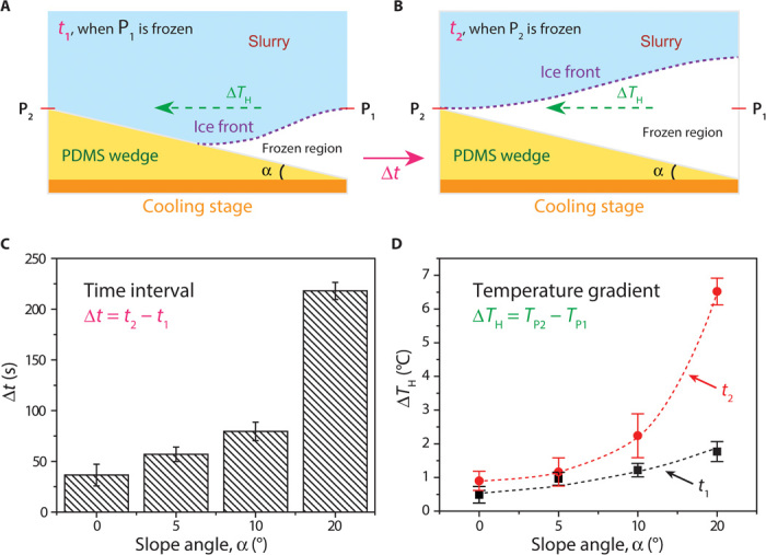
(A and B) PDMS wedges with slope angles α ranging from 0° to 20° were inserted between the slurry and the copper plate. Two thermocouple probes were placed on opposite walls of the mold at positions P1 and P2 corresponding to the height of the wedge. Times t1 and t2 correspond to the situations at which P1 and P2 get frozen, respectively. (C) As the slope angle was increased, the time interval Δt = t2 − t1 also increased, thereby demonstrating the gradient nucleation process. (D) The horizontal temperature gradient ΔTH (TP2 − TP1) corresponds to the difference of temperature between positions P1 and P2. At angles larger than 10°, a monodomain structure is created, with a significant horizontal temperature gradient observed at both t1 and t2.
Anisotropic architecture and resulting mechanical properties
On the basis of the above observations and analysis, bidirectional freeze casting markedly differs from unidirectional freeze casting in terms of the nucleation mode, growth of ice crystals, and hence the alignment in the final structure. Consequently, we systematically studied the effects of PDMS wedges on the final structural features of the scaffold (table S1) because this is of particular importance for the mechanical properties of the final structures. Samples prepared by unidirectional freeze casting without PDMS films are denoted as “control.” The sample’s porosity (φ) was calculated by mass (m) and volume (V), taking density of HA as (ρHA = 3.15 g/cm3) and using the following equations
| (1) |
| (2) |
where ρrelative and ρ are the relative and apparent densities, respectively (24). The pore area (Ap), lamellar thickness (t), and interlamellar spacing (λ) were derived from SEM images with ImageJ software (see fig. S8 for the definition of the measured parameters). Figure S9 summarizes all the parameters (φ, Ap, t, and λ) obtained from structures created using bidirectional freeze casting. These data indicate that an increase in the cooling rate results in a decrease in both t and λ but without significant change in φ and Ap. These results are consistent with similar data obtained using conventional freeze casting (16, 25). We found that the presence of a wedge, regardless of its slope angle, had little effect on those structural parameters.
Conventional and monodomain scaffolds (5 × 10 × 10 mm) were prepared under different conditions before structural and mechanical property characterization (table S1). Compressive strength and Young’s modulus values were collected from at least four samples in each category and are shown in Fig. 6, A and B, respectively. Apparently, both strength and modulus increase with increasing cooling rate, which is again consistent with results in the literature on unidirectional freeze casting (16, 25). For a given cooling rate, both strength and modulus slightly decrease with increasing slope angle. This could be attributed to the difference in the PDMS wedge thicknesses, which resulted in different ice-front speeds even at the same cooling rate. Scaffolds prepared by conventional (control) and bidirectional (“α = 20°”) freezing were compared in the three spatial directions in terms of their strength and modulus (Fig. 6, C and D, and table S2). Scaffolds prepared by conventional freezing showed a single preferential direction corresponding to their alignment direction (z axis). However, scaffolds prepared by bidirectional freezing showed a significant strength and modulus increase when tested in the y direction, as opposed to the x direction. These results further indicate the high degree of anisotropy of the structure obtained by bidirectional freezing.
Fig. 6. Mechanical properties of scaffolds fabricated with varying cooling rates and slope angles.
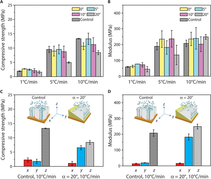
(A and B) Compressive strength (A) and Young’s modulus measurements (B) were performed. An increase in the cooling rate results in higher values of compressive strength and elastic modulus. Both strength and modulus decrease slightly with increasing slope angle, which could be attributed to the difference in the PDMS wedge thicknesses. Scaffolds, prepared using the unidirectional freeze-casting technique, were also tested for comparison and are listed as control. (C and D) For the control sample prepared by conventional freezing, only properties along the z axis are improved (strength and modulus) as compared to the other two axes. In contrast, in samples prepared by bidirectional freezing (α = 20°), both y and z axes have better properties as compared to the x axis. These data further indicate the high degree of anisotropy of the structure prepared by bidirectional freezing.
CONCLUSIONS
We have developed a bidirectional freeze-casting technique to fabricate large-scale (centimeter-scale) lamellar structures. Using HA powder, we investigated the mechanism of gradient nucleation and propagation of ice crystals under dual temperature gradients. This was achieved by placing a PDMS wedge with different slopes in between the cold finger and the slurry. In contrast to conventional unidirectional freeze casting, the bidirectional freeze-casting technique developed in this study can manipulate the alignment of ice crystals in two directions and can be applied to generate larger porous scaffolds with highly controlled, ordered structures. Although HA particles were used in this paper as a proof of concept, the technique can also be applied to multiple materials systems, for example, ceramic particles or platelets. Apart from the slope angle and the cooling rate, many other parameters, such as solid loading or various additive compounds, are currently being investigated in our laboratory for their effect on the bidirectional freezing technique. Our newly developed technique could thus provide an effective way of designing and manufacturing larger-scale novel, bioinspired, structural materials, especially advanced materials such as composites, where a higher level of control over the structure is required.
MATERIALS AND METHODS
Preparation of slurry
The slurry was prepared by mixing distilled water with HA powder [density, 3.15 g/cm3; d50 (median particle) size, 2.424 μm; 20 volume %] (Hydroxyapatite #30, Trans-Tech), 1 wt % of Darvan 811 (R.T. Vanderbilt Co.) as dispersant, 1 wt % of poly(ethylene glycol) (PEG-300, Sigma-Aldrich) as lubricant, and 2 wt % of Aquazol polymer (ISP) with a molecular weight of 50,000 g/mol as binder. The slurry was ball-milled for around 24 hours.
Preparation of PDMS wedge
Square Teflon tubes (18 ×18 × 40 mm) were sealed with a copper plate on one end and tilted to an angle of 0°, 5°, 10°, and 20°, respectively. PDMS (Sylgard 184, Dow Corning) was then poured into the mold to completely cover the copper plate. After curing at room temperature for more than 12 hours, PDMS wedges were obtained.
Bidirectional freezing and sintering
The cooling stage was composed of a liquid nitrogen tank and a copper rod, on top of which a Teflon mold (18 × 18 × 40 mm), along with a PDMS wedge and a copper plate, was placed. A ring heater, coiled around the copper rod, was linked to a power unit controlling the cooling rate. Thermocouples were inserted through the Teflon mold walls and connected to a computer to record the slurry temperature in situ at specific locations. After the slurry was poured into the mold, the temperature of the copper plate was progressively decreased at a controlled rate. When completely frozen, the sample was tapped out of the mold and freeze-dried for more than 48 hours at −50°C with 0.035-mbar pressure (Freeze Dryer 8, Labconco). An air furnace (1216BL, CM Furnaces Inc.) was finally used to sinter the green bodies (4 hours at 1300°C).
Characterization of the structural features of large-scale aligned lamellar structures
The lamellar structures of the scaffolds were analyzed using field-emission SEM (JSM-5700F SEM, JEOL) at an acceleration voltage of 15 kV, after being coated with gold by sputtering at 30 mA for 60 s. Fourier transform images were obtained using ImageJ. Structural parameters, such as lamellar thickness (t) and interlamellar spacing (λ), were manually measured on lines perpendicular to the ceramic walls. The pore area percentage (Ap) was defined as the void area divided by the total area. For each parameter, more than 100 measurements were performed. The colored images showing multiple domain orientations were obtained by processing the SEM images using the freeware GIMP 2.8. A high-speed CCD camera was used to record the ice profile propagation during the freezing process.
Compressive test of scaffolds
Compressive strengths were measured by performing uniaxial tests on blocks (10 × 10 × 5 mm) cut from the sintered specimens using a low-speed diamond saw. Surface grinding was conducted on the blocks to ensure that the two tested ends were flat and parallel. Samples were then compressed in the direction parallel to the pore orientation in an Instron 5944 screw-driven mechanical testing system at a displacement rate of 0.5 mm/min. At least five samples were tested for each condition to obtain statistically reliable values.
Supplementary Material
Acknowledgments
We acknowledge G. Lau, J. Wu, D. Don Lopez, and J. De Coninck for their help with the experiments and discussions. Funding: This work was supported by the Mechanical Behavior of Materials Program at the Lawrence Berkeley National Laboratory, funded by the Materials Sciences and Engineering Division, Office of Basic Energy Sciences, Office of Science, U.S. Department of Energy (DOE), under contract no. DE-AC02-05CH11231. We also acknowledge support of the x-ray tomography Beamline 8.3.2 at the Advanced Light Source at Lawrence Berkeley National Laboratory, which is supported by DOE’s Office of Basic Energy Sciences. Data measured in this study are available from H.B. at hbai@zju.edu.cn. Author contributions: H.B., A.P.T., and R.O.R. designed the research; H.B., Y.C., and B.D. performed the experiments; and H.B., B.D., A.P.T., and R.O.R. prepared the manuscript. Competing interests: The authors declare that they have no competing interests. Data and materials availability: All data needed to evaluate the conclusions in the paper are present in the paper and/or the Supplementary Materials. Additional data related to this paper may be requested from the authors.
SUPPLEMENTARY MATERIALS
Supplementary material for this article is available at http://advances.sciencemag.org/cgi/content/full/1/11/e1500849/DC1
Fig. S1. Representative SEM image of HA scaffold prepared by bidirectional freezing in the cross section perpendicular to the cold finger.
Fig. S2. Representative SEM image of HA scaffold in the cross section perpendicular to the cold finger.
Fig. S3. X-ray computed microtomography images for scaffolds prepared by (A) conventional and (B) bidirectional freezing.
Fig. S4. Processing of SEM images.
Fig. S5. Original SEM images of samples prepared under various conditions.
Fig. S6. Optical images showing ice profiles during freeze casting under dual temperature gradients with α = 10°, but at different cooling rates.
Fig. S7. Temperature measurements during conventional and bidirectional freeze casting.
Fig. S8. Representative SEM image of the cross section of a freeze-cast HA scaffold illustrating the different structural features and parameters.
Fig. S9. Structural parameters of HA scaffolds fabricated by bidirectional freezing.
Table S1. Porosity, pore area, lamellar thickness, interlamellar spacing, compressive strength, and Young’s modulus values for scaffolds prepared with different cooling rates (1, 5, and 10°C/min) and slope angles (0°, 5°, 10°, and 20°).
Table S2. Compressive strength and Young’s modulus values for scaffolds prepared by conventional (control) and bidirectional (α = 20°) freezing, both at 10°C/min.
REFERENCES AND NOTES
- 1.Wegst U. G. K., Bai H., Saiz E., Tomsia A. P., Ritchie R. O., Bioinspired structural materials. Nat. Mater. 14, 23–36 (2015). [DOI] [PubMed] [Google Scholar]
- 2.Chen P.-Y., McKittrick J., Meyers M. A., Biological materials: Functional adaptations and bioinspired designs. Prog. Mater. Sci. 57, 1492–1704 (2012). [Google Scholar]
- 3.Meyers M. A., McKittrick J., Chen P.-Y., Structural biological materials: Critical mechanics-materials connections. Science 339, 773–779 (2013). [DOI] [PubMed] [Google Scholar]
- 4.Yang W., Chen I. H., Gludovatz B., Zimmermann E. A., Ritchie R. O., Meyers M. A., Natural flexible dermal armor. Adv. Mater. 25, 31–48 (2013). [DOI] [PubMed] [Google Scholar]
- 5.Lin A., Meyers M. A., Growth and structure in abalone shell. Mater. Sci. Eng. A 390, 27–41 (2005). [Google Scholar]
- 6.Nettleship I., Applications of porous ceramics. Key Eng. Mater. 122–124, 305–324 (1996). [Google Scholar]
- 7.Fu Q., Rahaman M. N., Dogan F., Bal B. S., Freeze-cast hydroxyapatite scaffolds for bone tissue engineering applications. Biomed. Mater. 3, 025005 (2008). [DOI] [PubMed] [Google Scholar]
- 8.Deville S., Saiz E., Tomsia A. P., Freeze casting of hydroxyapatite scaffolds for bone tissue engineering. Biomaterials 27, 5480–5489 (2006). [DOI] [PubMed] [Google Scholar]
- 9.Chino Y., Dunand D. C., Directionally freeze-cast titanium foam with aligned, elongated pores. Acta Mater. 56, 105–113 (2008). [Google Scholar]
- 10.Chen Y., Bunch J., Li T., Mao Z., Chen F., Novel functionally graded acicular electrode for solid oxide cells fabricated by the freeze-tape-casting process. J. Power Sources 213, 93–99 (2012). [Google Scholar]
- 11.R. W. Rice, Porosity of Ceramics: Properties and Applications (CRC Press, New York, 1998). [Google Scholar]
- 12.Ohji T., Fukushima M., Macro-porous ceramics: Processing and properties. Int. Mater. Rev. 57, 115–131 (2012). [Google Scholar]
- 13.Studart A. R., Gonzenbach U. T., Tervoort E., Gauckler L. J., Processing routes to macroporous ceramics: A review. J. Am. Ceram. Soc. 89, 1771–1789 (2006). [Google Scholar]
- 14.Fu Q., Saiz E., Tomsia A. P., Direct ink writing of highly porous and strong glass scaffolds for load-bearing bone defects repair and regeneration. Acta Biomater. 7, 3547–3554 (2011). [DOI] [PMC free article] [PubMed] [Google Scholar]
- 15.Deville S., Saiz E., Nalla R. K., Tomsia A. P., Freezing as a path to build complex composites. Science 311, 515–518 (2006). [DOI] [PubMed] [Google Scholar]
- 16.Munch E., Launey M. E., Alsem D. H., Saiz E., Tomsia A. P., Ritchie R. O., Tough, bio-inspired hybrid materials. Science 322, 1516–1520 (2008). [DOI] [PubMed] [Google Scholar]
- 17.Bouville F., Maire E., Meille S., Van de Moortèle B., Stevenson A. J., Deville S., Strong, tough and stiff bioinspired ceramics from brittle constituents. Nat. Mater. 13, 508–514 (2014). [DOI] [PubMed] [Google Scholar]
- 18.Zhang H., Hussain I., Brust M., Butler M. F., Rannard S. P., Cooper A. I., Aligned two- and three-dimensional structures by directional freezing of polymers and nanoparticles. Nat. Mater. 4, 787–793 (2005). [DOI] [PubMed] [Google Scholar]
- 19.Gao H.-L., Xu L., Long F., Pan Z., Du Y.-X., Lu Y., Ge J., Yu S.-H., Macroscopic free-standing hierarchical 3D architectures assembled from silver nanowires by ice templating. Angew. Chem. Int. Ed. 53, 4561–4566 (2014). [DOI] [PubMed] [Google Scholar]
- 20.Hunger P. M., Donius A. E., Wegst U. G. K., Platelets self-assemble into porous nacre during freeze casting. J. Mech. Behav. Biomed. Mater. 19, 87–93 (2013). [DOI] [PubMed] [Google Scholar]
- 21.Barg S., Perez F. M., Ni N., do Vale Pereira P., Maher R. C., Garcia-Tuñon E., Eslava S., Agnoli S., Mattevi C., Saiz E., Mesoscale assembly of chemically modified graphene into complex cellular networks. Nat. Commun. 5, 4328 (2014). [DOI] [PMC free article] [PubMed] [Google Scholar]
- 22.Delattre B., Bai H., Ritchie R. O., De Coninck J., Tomsia A. P., Unidirectional freezing of ceramic suspensions: In situ X-ray investigation of the effects of additives. ACS Appl. Mater. Interfaces 6, 159–166 (2014). [DOI] [PubMed] [Google Scholar]
- 23.Deville S., Saiz E., Tomsia A. P., Ice-templated porous alumina structures. Acta Mater. 55, 1965–1974 (2007). [Google Scholar]
- 24.Porter M. M., Imperio R., Wen M., Meyers M. A., McKittrick J., Bioinspired scaffolds with varying pore architectures and mechanical properties. Adv. Funct. Mater. 24, 1978–1987 (2014). [Google Scholar]
- 25.Deville S., Maire E., Lasalle A., Bogner A., Gauthier C., Leloup J., Guizard C., In situ X-ray radiography and tomography observations of the solidification of aqueous alumina particle suspensions—Part I: Initial instants. J. Am. Ceram. Soc. 92, 2489–2496 (2009). [Google Scholar]
- 26.Munch E., Saiz E., Tomsia A. P., Deville S., Architectural control of freeze-cast ceramics through additives and templating. J. Am. Ceram. Soc. 92, 1534–1539 (2009). [Google Scholar]
- 27.Bouville F., Portuguez E., Chang Y., Messing G. L., Stevenson A. J., Maire E., Courtois L., Deville S., Templated grain growth in macroporous materials. J. Am. Ceram. Soc. 97, 1736–1742 (2014). [Google Scholar]
Associated Data
This section collects any data citations, data availability statements, or supplementary materials included in this article.
Supplementary Materials
Supplementary material for this article is available at http://advances.sciencemag.org/cgi/content/full/1/11/e1500849/DC1
Fig. S1. Representative SEM image of HA scaffold prepared by bidirectional freezing in the cross section perpendicular to the cold finger.
Fig. S2. Representative SEM image of HA scaffold in the cross section perpendicular to the cold finger.
Fig. S3. X-ray computed microtomography images for scaffolds prepared by (A) conventional and (B) bidirectional freezing.
Fig. S4. Processing of SEM images.
Fig. S5. Original SEM images of samples prepared under various conditions.
Fig. S6. Optical images showing ice profiles during freeze casting under dual temperature gradients with α = 10°, but at different cooling rates.
Fig. S7. Temperature measurements during conventional and bidirectional freeze casting.
Fig. S8. Representative SEM image of the cross section of a freeze-cast HA scaffold illustrating the different structural features and parameters.
Fig. S9. Structural parameters of HA scaffolds fabricated by bidirectional freezing.
Table S1. Porosity, pore area, lamellar thickness, interlamellar spacing, compressive strength, and Young’s modulus values for scaffolds prepared with different cooling rates (1, 5, and 10°C/min) and slope angles (0°, 5°, 10°, and 20°).
Table S2. Compressive strength and Young’s modulus values for scaffolds prepared by conventional (control) and bidirectional (α = 20°) freezing, both at 10°C/min.


