Abstract
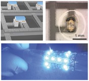
Intrinsically stretchable multilayer circuit boards are fabricated with a fast and material efficient method based on filtration. Silver nanowire conductor patterns of outstanding performance are defined by filtration through wax printed membranes and the circuit board is assembled by subsequent transfers of the nanowires onto the elastomer substrate. The method is used to fabricate a bright stretchable light emitting diode matrix display.

Keywords: filtration, silver nanowires, stretchable displays, stretchable electronics, wax printing
The prospects of electronics that can withstand large mechanical deformations and conform to curvilinear surfaces have led to the development of stretchable electronic skins,1 displays,2 wearables,3 and medical implants.4 Although intrinsically stretchable circuit elements, such as transistors,5 capacitors,6 and light‐emitting electrochemical cells,[[qv: 2b]] have been developed, these components will not be able to match the performance of their rigid counterparts. Therefore, many stretchable electronic applications will require the mounting of rigid components onto stretchable circuit boards (SCBs), where the SCB accounts for the mechanical deformation of the system. Thus, it is of great importance to develop high performance multilayer SCBs that are fast, easy and cheap to produce. Here we address this challenge by developing a simple and fast process for fabricating SCBs based on a highly conductive (≈20 000 S cm−1) and stretchable silver nanowire (AgNW) composite. Filtration membranes, which are patterned by a standard wax printer, are used to define the AgNW conductor layers. We demonstrate the capability of the method by developing a bright stretchable light emitting diode (LED) matrix display, which can be wrapped around curved objects and stretched up to 20%. The whole multilayer process, from design to completed device, can be carried out in a single day.
There are two main approaches to implement SCBs; the use of accommodating geometries that protect rigid conductors from strain,7 or the use of intrinsically stretchable conductors comprising a conductive filler in an elastomer matrix.8 The later approach has the advantage of less geometrical constraints but uses novel nanomaterial composites that need to be processed and patterned efficiently. A patterning method for SCBs should preferably be fast, simple, material efficient and resulting in high performance conductors. Conventional CBs often use copper conductors with sheet resistance in the mΩ/sq range. Although such a low value is hard to achieve with stretchable composites, it is of great importance to keep the sheet resistance well below 1 Ω sq−1 for many applications, e.g., for bright LEDs. To achieve this while keeping the conductor thickness within a reasonable range, the conductivity of the composite needs to be really high. Printing techniques are attractive for SCB fabrication due to their simplicity and scalability.[[qv: 2a]],9 However, the ink formulation and printing process put restraints on the materials used and the conductivities achieved is typically in the 100–800 S cm−1 range, which is significantly lower than what is achieved with other methods. Filtration is an alternative for the formation of dense highly conductive films of high aspect ratio materials[[qv: 8d]],10 The nanomaterial is dispersed in a solvent and deposited on top of a membrane when the dispersion is filtered through, after which the film can be transferred to an elastomer substrate. The conductor can also be patterned by putting a plastic mask on top of the filter;[[qv: 8d]] however, this approach provides limited resolution and severe constraints on possible patterns. To circumvent these limitations, here we developed an efficient and easy way of fabricating SCBs by patterned filtration. Inspired by previous work on paper microfluidics,11 we pattern the membranes with a desktop wax printer in order to define the conductor pattern. We demonstrate the versatility of this method by constructing a multilayer SCB comprising a fully addressable LED matrix.
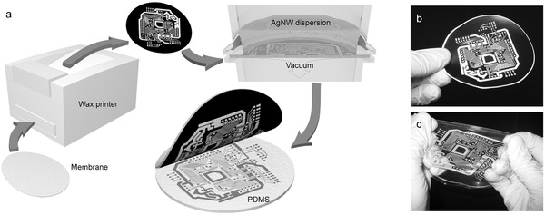
Hydrophilic PVDF membranes are taped onto a carrier paper and the desired wax patterned is printed on the membrane with a desktop wax printer (Figure 1 a). The patterned membrane is soaked in deionized (DI) water and mounted into a filtration setup. An aqueous dispersion of silver nanowires (AgNWs) is filtered through the part of the membrane not covered in wax, depositing the AgNWs on the surface. The membrane is dried and put in contact with a substrate of semicured PDMS. After applying pressure the membrane is soaked in DI water and peeled off, leaving the AgNW pattern on the PDMS substrate. Two different sizes of membranes were employed, 47 and 90 mm in diameter. Figure 1b shows a 90 mm membrane patterned with black wax and the corresponding transferred AgNW pattern is shown in Figure 1c. The pattern is fully transferred without any visible defects and the whole substrate is soft and can be repeatedly stretched. The amount of residual AgNWs outside of the defined patterns is very low (Figure S2, Supporting Information), probably due to the dewetting of the wax areas during the end phase of the filtration, which prevents deposition of AgNWs by drying. The hydrophobicity of the wax also makes the pattern resistant to small cracks, as the water cannot wet these cracks (Figure S2c–e, Supporting Information).
Figure 1.

Nanowire conductor patterning. a) The PVDF membrane is mounted on a paper carrier and the wax pattern is printed onto the membrane. The patterned membrane is mounted in a filtration setup and the AgNW dispersion is filtered through the uncovered areas of the membrane. The AgNW pattern is transferred to a semicured PDMS substrate under pressure and finally the membrane is peeled off. b) Example of a wax pattern printed onto a membrane of 90 mm in diameter. c) The AgNW pattern has been transferred onto a stretchable PDMS substrate.
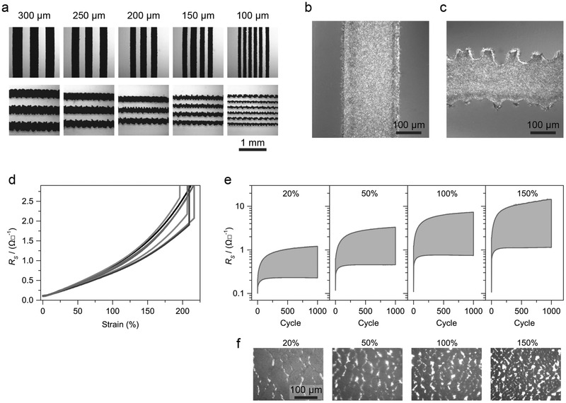
The resolution of the wax printer (600 dpi) limits the minimum feature size of the AgNW pattern. In order to determine the smallest attainable features, a series of AgNW test patterns were fabricated (Figure 2 a). The lines in the print direction have even edges and linewidths down to 100 μm can be patterned, although the linewidth and spacing can vary a bit. The lines perpendicular to the print direction exhibit significantly higher roughness and 150 μm seems to be the lowest feasible linewidth in this case. Figure 2b,c shows the difference in more detail. The roughness of the perpendicular lines is typically around 40 μm, but can be up to 70 μm locally. This makes sense as 600 dpi corresponds to a dot spacing of 42 μm. One should also notice that the print should be in pure black, as the use of several colors seems to result in rougher edges.
Figure 2.

AgNW conductor pattern quality and performance. a) The images show transferred AgNW conductor lines of different dimension and orientation. Linewidths down to 100 μm can be achieved for lines in the print direction, although the actual line width and spacing can vary quite a bit. For lines perpendicular to the print direction, the lowest feasible dimension is 150 μm. b) The edges of the vertical lines are smooth with little variation. c) The edges of the perpendicular lines are uneven with a typical roughness in the 40 μm range, although variations up to 70 μm can be observed. d) Seven samples with AgNW tracks of 500 μm width and 20 mm length were stretched until mechanical failure. The sheet resistance remained below 1 Ω sq−1 even at 100 % strain. The samples mechanically broke at around 200 % strain. e) For samples that were cycled to 20 %, 50 %, 100 %, and 150 % strain 1000 times, the sheet resistance initially increased rapidly but later stabilized. f) Bright field images of stretched samples that have been cycled 1000 times. The amount of internal fractures within the AgNW films increase with strain.
The sheet resistance of an AgNW conductor depends on the amount of deposited material. For thicknesses (t) well above the percolation limit the sheet resistance scales approximately as ≈1/t. Thus the desired sheet resistance can be obtained by adjusting the amount of AgNWs in the dispersion used for filtration. For LED applications the currents are often quite high and thus the sheet resistance should be well below 1 Ω sq−1. To make sure our conductors fulfilled this criterion, we performed electromechanical characterization of samples with AgNW coverage of 0.8 mg cm−2. The initial sheet resistance for the samples was 0.11 ± 0.01 Ω sq−1, which corresponds to a conductivity of ≈20000 S cm−1 for the 5 μm thick conductor (Figure S1, Supporting Information). When stretched until failure (≈200%), the resistance increased with the strain but remained below 0.4 Ω sq−1 up to 50% strain (Figure 2d). In comparison to the results reported by Xu et al.,[[qv: 8e]] our initial conductivity of 20 000 S cm−1 is significantly higher than their reported value of 8100 S cm−1, while at 50% strain our conductivity dropped by a factor of 4 and theirs dropped by a factor of 3. Another important aspect is how the resistance evolves under strain cycling. Figure 2e shows the result of 1000 cycles of 20%, 50%, 100%, and 150% strain. Initially, the resistance increased rapidly but after a while the rate of increase slowed down and stabilized. After 1000 cycles at 20% the resistance was 0.23 Ω sq−1, a twofold increase of the initial value. The resulting AgNW film morphologies in the stretched state after 1000 cycles are shown in Figure 2f. The amount of formed cracks increases with the applied strain. However, for larger strains the film still forms a connected network and the sheet resistance remains quite low.
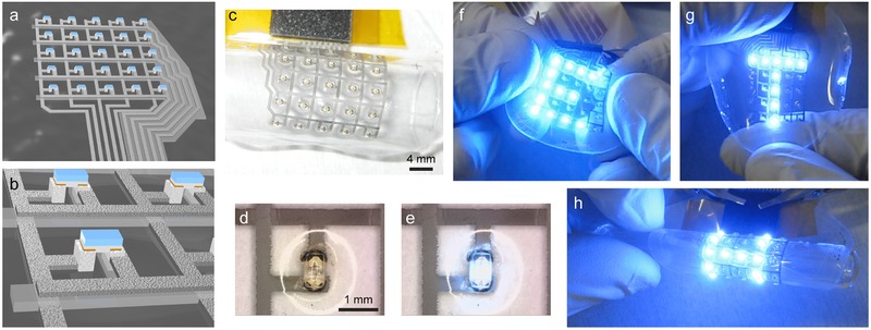
Encouraged by the above results, we went on to the design and fabricate a LED matrix display. The display comprises two AgNW conductor layers and 5 × 5 blue LEDs (Figure 3 a). Each LED is connected to one row and one column line, which allows the display to be updated row by row and thereby generating arbitrary images when connected to a Rainbowduino LED driver. The fabrication starts by transferring the bottom AgNW conductor onto a PDMS substrate (see Figure S3 of the Supporting Information for details). Next, a thin layer of PDMS is patterned onto the substrate by spin coating it over a laser cut foil. The second AgNW conductor layer is transferred onto the patterned PDMS and mounting pads of silver epoxy are stencil printed. The LEDs are placed in a laser cut holder and all LEDs are simultaneously transferred to the substrate by bringing them in contact with the silver epoxy pads. The resulting structure can be seen in Figure 3b. Finally, a protecting layer of PDMS is spin coated on top of the device. The resulting LED matrix wrapped around a glass cylinder is shown in Figure 3c. A closer look shows that the LEDs are properly aligned and mounted onto the AgNW conductors (Figure 3d,e). The LED matrix can be stretched to about 20% strain and wrapped around cylinders without losing functionality (Figure 3f–h). When the strain is increased above 20%, more and more LEDs lose their electrical contact. The failure typically occurs at the contact between the AgNWs and the harder silver epoxy.
Figure 3.

Stretchable LED diode matrix. a) The LED matrix comprises 5 × 5 LEDs, each connected to one vertical and one horizontal addressing line. All the addressing lines are collected on one side to form the contact. b) The two addressing planes are isolated from each other by a thin patterned PDMS layer. The LEDs are mounted on top of two printed silver epoxy pads. c) The fabricated LED matrix wrapped around a glass cylinder. The LEDs are separated by 4 mm. d,e) The LED is shown in the off and on state. The circular reflection arises from the PDMS protection layer on top. f–h) The LED matrix can withstand stretching to about 20% or wrapping around a glass cylinder. The pictures were taken under ambient light conditions, which demonstrate the brightness of the LEDs.
In conclusion, we have demonstrated a simple and efficient way of fabricating a bright stretchable LED matrix display. The high brightness was enabled by the outstanding performance of our AgNW conductors, which had an initial conductivity of ≈20 000 S cm−1 and a sheet resistance of 0.11 Ω sq−1, the best values reported so far for stretchable composites.[[qv: 8c]] The exceptionally high conductivity is likely due to compression of the AgNW films during transfer, causing the AgNW volume fraction to go up. The fabricated LED matrix was very flexible and could be stretched up to 20% while maintaining functionality. The limiting factor for the stretchability was the AgNW‐silver epoxy interface. This might be improved by employing softer contact pads or by relieving the whole interface of strain by the incorporation of stiff islands. Since the patterning technique is built around wax printing and laser cutting, the time from design to completed device was less than a day. Other attractive features of the approach are the low material consumption, the wide range of materials that may be processed and the possibility to significantly upscale as wax printers can handle formats up to A3. We therefore believe that the presented approach can be a valuable tool for future development of stretchable electronic systems.
Experimental Section
AgNW Filtration: Hydrophilic PVDF membranes (0.22 μm pore size, Millipore) were taped onto carrier paper and patterned with a Xerox ColorCube 8570N wax printer (pure black, photo quality). AgNWs (60 nm diameter, 10 μm long, Sigma‐Aldrich) were dispersed in ethanol to a concentration of 2 mg mL−1, vortexed and briefly ultrasonicated. Immediately prior to filtration, the AgNWs were dispersed in 20 mL DI water and vortexed. A patterned membrane was soaked in DI water and then mounted in the filtration setup. The dispersion was filtered through the membrane and the membrane with the deposited AgNWs was dried on a hotplate (40 °C, 20 min). The surface coverage of the AgNW pattern was 0.8 mg cm−2.
LED Matrix Fabrication: Glass wafers were O2‐plasma treated (300 W, 2 min) and vapor phase silanized in vacuum (1h, Trichloro(1H,1H,2H,2H‐perfluorooctyl)silane, Sigma‐Aldrich). A thin layer of release agent (Ease Release 205, Mann Release Technologies) was spin coated (3000 rpm, 20 s) onto a silanized wafer. Next, a layer of PDMS (Sylgard 184, Dow Corning) was spin coated (1000 rpm, 30 s) and semicured on a hotplate (70 °C, 6 min). The bottom AgNW conductor layer was transferred by putting the patterned membrane in contact with the PDMS, apply pressure, soak the stack in DI water and peel off the membrane. A mask was cut out of 25 μm thick PEN foil (Teonex Q51) with a laser cutter (Trotec Speedy 300). The mask was placed onto the substrate with a manual alignment setup based on a XYZθ micromanipulator. A 20 μm thick PDMS layer was spin coated over the mask, after which the mask was peeled off. The added PDMS pattern was semi‐cured and the second AgNW conductor pattern was transferred, after which the substrate was cured on a hotplate (100 °C, 1 h). A mask for the pads was laser patterned from 50 μm PMMA foil (Goodfellow) and aligned onto the substrate. Silver epoxy (8330S Silver Conductive Epoxy Adhesive, MGchemicals) was diluted in ethanol (400 μL epoxy, 100 μL ethanol) and stencil printed through the PMMA mask to create the contact pads. The pads were dried on a hotplate (70 °C, 10 min). A 125 μm thick PEN foil (Teonex Q51) was lasercut and glued on a wafer to create a holder for the LEDs (VAOL‐S4SB4, VCC). The LEDs were placed upside down in the holder and transferred all at once to the substrate by gently pressing them to the contact pads, after which the silver epoxy was cured on a hotplate (100 °C, 1 h). The epoxy pads were briefly incubated in a dilute platinic acid solution to minimize PDMS curing inhibition. Finally, a protective PDMS layer was spin coated on top of the LEDs (1000 rpm, 30 s) while protecting the contacts and the whole device was cured on a hotplate (100 °C, 1 h).
Electromechanical Characterization: Samples with 500 μm wide and 20 mm long AgNW tracks were clamped in a tensile testing machine (DO‐FB0.5TS, Zwick/Roell). Eutectic gallium–indium (Sigma‐Aldrich) was used to make electrical contact between copper pads and the AgNW tracks. The resistance was measured with a digital multimeter (Agilent 34401A) at 4 Hz. The stretching speed for maximum strain tests was 0.5 mm s−1 and 2 mm s−1 for cycling tests.
Supporting information
As a service to our authors and readers, this journal provides supporting information supplied by the authors. Such materials are peer reviewed and may be re‐organized for online delivery, but are not copy‐edited or typeset. Technical support issues arising from supporting information (other than missing files) should be addressed to the authors.
Supplementary
Supplementary
Acknowledgements
The authors acknowledge S. Wheeler and M. Lanz for their valuable technical support and F. Stauffer for fruitful discussions. The research was financed by the Swedish Research Council (637‐2013‐7301), the Swiss Nanotera SpineRepair project, and ETH Zurich.
References
- 1.a) Hammock M. L., Chortos A., Tee B. C. K., Tok J. B. H., Bao Z., Adv. Mater. 2013, 25, 5997; [DOI] [PubMed] [Google Scholar]; b) Kim D.‐H., Lu N., Ma R., Kim Y.‐S., Kim R.‐H., Wang S., Wu J., Won S. M., Tao H., Islam A., Yu K. J., Kim T.‐i., Chowdhury R., Ying M., Xu L., Li M., Chung H.‐J., Keum H., McCormick M., Liu P., Zhang Y.‐W., Omenetto F. G., Huang Y., Coleman T., Rogers J. A., Science 2011, 333, 838. [DOI] [PubMed] [Google Scholar]
- 2.a) Sekitani T., Nakajima H., Maeda H., Fukushima T., Aida T., Hata K., Someya T., Nat. Mater. 2009, 8, 494; [DOI] [PubMed] [Google Scholar]; b) Liang J., Li L., Niu X., Yu Z., Pei Q., Nat. Photonics 2013, 7, 817. [Google Scholar]
- 3. Ren J., Zhang Y., Bai W., Chen X., Zhang Z., Fang X., Weng W., Wang Y., Peng H., Angew. Chem., Int. Ed. 2014, 53, 7864. [DOI] [PubMed] [Google Scholar]
- 4.a) Minev I. R., Musienko P., Hirsch A., Barraud Q., Wenger N., Moraud E. M., Gandar J., Capogrosso M., Milekovic T., Asboth L., Torres R. F., Vachicouras N., Liu Q., Pavlova N., Duis S., Larmagnac A., Vörös J., Micera S., Suo Z., Courtine G., Lacour S. P., Science 2015, 347, 159; [DOI] [PubMed] [Google Scholar]; b) Kim D.‐H., Lu N., Ghaffari R., Kim Y.‐S., Lee S. P., Xu L., Wu J., Kim R.‐H., Song J., Liu Z., Viventi J., de Graff B., Elolampi B., Mansour M., Slepian M. J., Hwang S., Moss J. D., Won S.‐M., Huang Y., Litt B., Rogers J. A., Nat. Mater. 2011, 10, 316; [DOI] [PMC free article] [PubMed] [Google Scholar]; c) Lacour S., Benmerah S., Tarte E., FitzGerald J., Serra J., McMahon S., Fawcett J., Graudejus O., Yu Z., Morrison B. III, Med. Biol. Eng. Comput. 2010, 48, 945. [DOI] [PubMed] [Google Scholar]
- 5.a) Chortos A., Koleilat G. I., Pfattner R., Kong D., Lin P., Nur R., Lei T., Wang H., Liu N., Lai Y.‐C., Kim M.‐G., Chung J. W., Lee S., Bao Z., Adv. Mater. 2015, DOI: 10.1002/adma.201501828; [DOI] [PubMed] [Google Scholar]; b) Liang J., Li L., Chen D., Hajagos T., Ren Z., Chou S.‐Y., Hu W., Pei Q., Nat. Commun. 2015, 6, 7647. [DOI] [PMC free article] [PubMed] [Google Scholar]
- 6.a) Huang Y., Tao J., Meng W., Zhu M., Huang Y., Fu Y., Gao Y., Zhi C., Nano Energy 2015, 11, 518; [Google Scholar]; b) Chen X., Qiu L., Ren J., Guan G., Lin H., Zhang Z., Chen P., Wang Y., Peng H., Adv. Mater. 2013, 25, 6436. [DOI] [PubMed] [Google Scholar]
- 7.a) Rogers J. A., Someya T., Huang Y., Science 2010, 327, 1603; [DOI] [PubMed] [Google Scholar]; b) Kaltenbrunner M., Sekitani T., Reeder J., Yokota T., Kuribara K., Tokuhara T., Drack M., Schwodiauer R., Graz I., Bauer‐Gogonea S., Bauer S., Someya T., Nature 2013, 499, 458; [DOI] [PubMed] [Google Scholar]; c) Zhang Y., Wang S., Li X., Fan J. A., Xu S., Song Y. M., Choi K.‐J., Yeo W.‐H., Lee W., Nazaar S. N., Lu B., Yin L., Hwang K.‐C., Rogers J. A., Huang Y., Adv. Funct. Mater. 2014, 24, 2028. [Google Scholar]
- 8.a) Kim Y., Zhu J., Yeom B., Di Prima M., Su X., Kim J.‐G., Yoo S. J., Uher C., Kotov N. A., Nature 2013, 500, 59; [DOI] [PubMed] [Google Scholar]; b) Park M., Im J., Shin M., Min Y., Park J., Cho H., Park S., Shim M.‐B., Jeon S., Chung D.‐Y., Bae J., Park J., Jeong U., Kim K., Nat Nano 2012, 7, 803; [DOI] [PubMed] [Google Scholar]; c) Yao S., Zhu Y., Adv. Mater. 2015, 27, 1480; [DOI] [PubMed] [Google Scholar]; d) Lee P., Lee J., Lee H., Yeo J., Hong S., Nam K. H., Lee D., Lee S. S., Ko S. H., Adv. Mater. 2012, 24, 3326; [DOI] [PubMed] [Google Scholar]; e) Xu F., Zhu Y., Adv. Mater. 2012, 24, 5117; [DOI] [PubMed] [Google Scholar]; f) Chun K.‐Y., Oh Y., Rho J., Ahn J.‐H., Kim Y.‐J., Choi H. R., Baik S., Nat. Nano 2010, 5, 853; [DOI] [PubMed] [Google Scholar]; g) Park M., Park J., Jeong U., Nano Today 2014, 9, 244; [Google Scholar]; h) Ge J., Yao H.‐B., Wang X., Ye Y.‐D., Wang J.‐L., Wu Z.‐Y., Liu J.‐W., Fan F.‐J., Gao H.‐L., Zhang C.‐L., Yu S.‐H., Angew. Chem., Int. Ed. 2013, 52, 1654; [DOI] [PubMed] [Google Scholar]; i) Larmagnac A., Eggenberger S., Janossy H., Voros J., Sci. Rep. 2014, 4, 7254. [DOI] [PMC free article] [PubMed] [Google Scholar]
- 9.a) Matsuhisa N., Kaltenbrunner M., Yokota T., Jinno H., Kuribara K., Sekitani T., Someya T., Nat. Commun. 2015, 6, 7461; [DOI] [PMC free article] [PubMed] [Google Scholar]; b) Sekitani T., Noguchi Y., Hata K., Fukushima T., Aida T., Someya T., Science 2008, 321, 1468. [DOI] [PubMed] [Google Scholar]
- 10. Yang S. B., Kong B.‐S., Jung D.‐H., Baek Y.‐K., Han C.‐S., Oh S.‐K., Jung H.‐T., Nanoscale 2011, 3, 1361. [DOI] [PubMed] [Google Scholar]
- 11.a) Lu Y., Shi W., Qin J., Lin B., Anal. Chem. 2010, 82, 329; [DOI] [PubMed] [Google Scholar]; b) de Lange V., Vörös J., Anal. Chem. 2014, 86, 4209. [DOI] [PubMed] [Google Scholar]
Associated Data
This section collects any data citations, data availability statements, or supplementary materials included in this article.
Supplementary Materials
As a service to our authors and readers, this journal provides supporting information supplied by the authors. Such materials are peer reviewed and may be re‐organized for online delivery, but are not copy‐edited or typeset. Technical support issues arising from supporting information (other than missing files) should be addressed to the authors.
Supplementary
Supplementary


