

Abstract
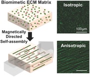
Biomimetic extracellular matrix (ECM) topographies driven by the magnetic‐field‐directed self‐assembly of ECM protein‐coated magnetic beads are fabricated. This novel bottom‐up method allows us to program isotropic, anisotropic, and diverse hybrid ECM patterns without changing other physicochemical properties of the scaffold material. It is demonstrated that this 3D anisotropic matrix is able to guide the dendritic protrusion of cells.
Keywords: 3D biomaterials, biomimetic extracellular matrix, extracellular matrix topography, magnetic‐field‐directed self‐assembly
Tissues display highly anisotropic, heterogeneous, nonlinear physical properties that vary widely and depend on the composition, architecture, and pathology.1 Within these tissues, cells reside in a complex 3D environment composed of heterogeneous biological building blocks in a variety of arrangements featuring diverse geometries, dimensionalities, and material properties.1 The biophysical interactions between cells and these architectures have a profound impact on cell processes such as differentiation, migration, and proliferation.2, 3, 4, 5, 6, 7 One major tissue component is the extracellular matrix (ECM), which serves as a physical scaffold but also controls chemical cues, serving as a reservoir for cytokines and nutrients, and as a patchbay for integrin‐mediated mechano‐signals.8, 9 At the epithelia–stroma interface, dynamically regulated ECM proteins of the basement membrane program tissue polarization, and compartmentalize epithelial tissue from the stroma via the interstitial matrix. Structurally diverse ECM architectures composed of proteins such as laminins (LN), collagens, and fibronectin (FN) are topographically distinct, thus playing a primary role in providing physical and spatial cues to which cells respond in combination with biochemical cues.1, 10
Therefore, to recreate the topographical and chemical heterogeneity of ECM architectures, 3D biomimetic scaffolds have been used to approximate the in vivo architectural and signaling cues provided by the ECM for real‐time visualization of single cell dynamics and multicellular assembly.11, 12, 13 To dynamically tune physical architecture of these hydrogels, the proteins are commonly cross‐linked. Specifically, reconstituted laminin rich ECM (e.g., Matrigel), a common substrate for epithelial cells, forms amorphous gels with no fibrils or spatial heterogeneities on cellular length scales. In contrast, collagen type I hydrogels can be tailored to form fibrillar architectures by tuning polymerization conditions including protein concentration, temperature, and pH.14, 15 But matrix rigidity inevitably, and sometimes undesirably, increases with protein concentration.16
Also, techniques such as photolithographic patterning, electrospinning, and molecular self‐assembly have been employed to recreate 3D topography.17, 18 Lithographic methods such as multiphoton chemical patterning and photodegradation selectively expose functional groups one at a time with multiphoton excitation to immobilize the desired oligopeptides for each site of ligand binding in a surrogate ECM hydrogel.19, 20, 21 These methods produce very precise patterns of adhesion ligands in a hydrogel but can only be used with certain types of materials and they are largely low‐throughput. Additionally, the cells are exposed to chemicals and irradiation during the fabrication process. A low cost alternative is the method of electrospinning. Briefly, this process involves “jetting” to transform an electrically charged polymer solution into nanofibers with a distinct chemistry to achieve scaffolds with tunable mechanical properties.22, 23 Cells cannot be incorporated in situ using this method, due to the deleterious effects of the solvents and the electric fields applied during fabrication. In addition, the jetting process employed to generate nanofibers can only achieve specific 3D geometries. As a bottom‐up approach, molecular self‐assembly of amphiphile peptides by their noncovalent molecular interactions generates nanofibrillar supermolecules that are similar in architecture to that of native ECMs such as type I collagens and fibronectin.24, 25, 26, 27 However, tuning the mechanical properties or geometrical arrangement of the nanofibers used in the construction of 3D structures is not readily achieved with this method. Therefore, a key goal in engineering 3D bioscaffolds is to develop a method that is able to incorporate topographical features with physicochemical cues in a more controlled, independent, and high‐throughput manner.
Therefore, despite our extensive understanding of the biochemical reactions that control cellular fates, dissecting the role of physical cues that also modulate or may potentially override signals due to biochemical cues remains elusive. Moreover, one outstanding question is how to decouple topography from other physicochemical or biological variables such as stiffness, porosity, or molecular composition.28, 29, 30 Here, we program topographies in 3D biomaterials using magnetic‐field‐directed self‐assembly of surface‐functionalized magnetic particles serving as the tissue building blocks. This approach presents a tissue‐mimetic platform to dissect the role of topographical cues received from fibrillar geometries from that due to the chemical composition of the ECM in surrogate 3D hydrogels.
EDC (1‐ethyl‐3‐(3‐dimethylaminopropyl)‐carbodiimide) is a zero‐length cross‐linking agent. The EDC‐mediated coupling process is one of the most readily available and versatile methods for cross‐linking proteins to carboxylic acid in aqueous solution.31 Surface functionalization of particles is performed prior to hydrogel polymerization. Hence, alternative functionalization can be used and it is largely independent of matrix composition. Briefly, we cross‐link ECM proteins to the activated surfaces of 300 nm superparamagnetic particles (Figure 1 a, step 1). We chose relatively large particles to overcome the viscous resistance of polymers, minimize the assembling time, and prevent particle engulfment of cells during the fabrication process. These functionalized magnetic particles are then mixed with cells in liquid ECM or mixed in liquid ECM alone (Figure 1a, step 2). A magnetic field is then applied to this mixture well before polymerization of the hydrogel, to facilitate assembly of long chain‐like nanostructures.32, 33, 34 The applied magnetic field is sufficient to overcome the rheological resistance within the hydrogel (Figure 1a, step 3). Self‐organization into specific geometric patterns with defined anisotropy is achieved by simply controlling the external field arrangement. After chains are formed with desired dimensions, the matrix is polymerized to preserve the programmed topography (Figure 1a, step 4, c,d,f,g and Figure S1, Supporting Information). The magnetic field is then removed. Here, for comparison, a control sample with no magnetic field applied was also fabricated wherein the particles were randomly distributed throughout the matrix (Figure 1b,e).
Figure 1.
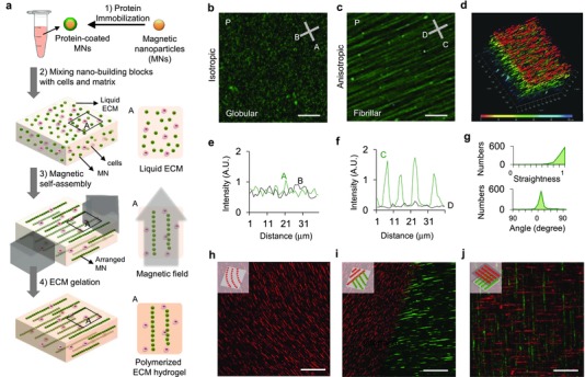
Self‐assembly of functionalized magnetic particles (MNs) creates diverse topographies in 3D. a) A schematic of the fabrication process. b,e) Isotropic topography composed of randomly dispersed particles coated with green fluorescent fibronectin. c,f) Anisotropic (fibril) topography composed of self‐assembled particles. d) Fibril topography in 3D. g) The straightness (upper graph) and the orientation (lower graph) of nanofibers in the anisotropic topography. h) Curved nanofibers fabricated by the application of a curved magnetic field. i) Two adjoining topographies with different surface proteins and orientations (red: laminin, green: fibronectin). j) Two stacked topographies with different surface proteins and orientations. Scale bars, 30 μm for (b)–(d) and 100 μm for (h)–(j).
One advantage of this method is the relative ease of engineering 3D hydrogels with nano‐ to microscale topographies featuring rectilinear anisotropy (Figure S2, Supporting Information). Moreover, curvilinear chains can be created simply by modulating the curvature of the applied magnetic field line, as their assembly follows in the same direction as that of the magnetic field line (Figure 1c,h). Complex structures with multiple topographic geometries can also be fabricated by altering the magnetic field in sequential matrix polymerization steps. We created hybrid environments in which we stacked layers or formed composites with different alignments and ECM proteins (Figure 1i,j and Figure S3, Supporting Information). We controlled the physical dimensions of the nanochains such as their length, width, and interchain distance, by either adjusting the duration of the applied magnetic field, the diameter of particles, or the initial concentration of the particles (Figure 2 a–d and Figure S4, Supporting Information). An example is shown in a schematic depicting the interplay between particle chain length and duration of the applied magnetic field (Figure 2b). The length and interchain distances are coupled. As chain length increases, more particles are needed for chain elongation, thus fewer chains are formed (Figure 2d). Also, the width distribution of chains varies according to the diameter of the particles (Figure 2c).
Figure 2.
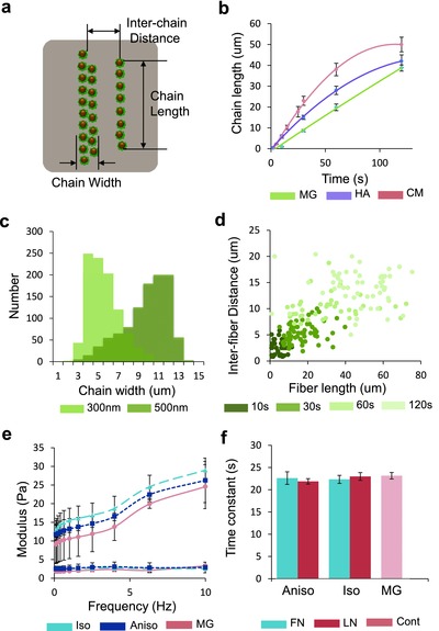
Topographies formed by particle self‐assembly can be created in a controlled and independent manner. a) Schematic of nanochain dimensions. b) Self‐assembling profile of chain length according to the magnetic field application time in Matrigel (MG), hyaluronic acid (HA), and culture media (CM). c) Distribution of chain width according to particle diameter. d) Interchain distance of nanochains in correlation with nanochain length and magnetic field application time. e) Bulk dynamic modulus of isotropic, anisotropic, and pure Matrigel matrix in a frequency range of 1–10 Hz (upper curves: storage modulus, lower curves: loss modulus). f) Characteristic diffusion times of isotropic, anisotropic matrices composed of fibronectin (FN) and laminin (LN)‐coated magnetic particles and pure Matrigel measured by FRAP. Each bar represents ten cases from two samples. Error bars show standard errors.
So how do we decouple topography from other physicochemical or biological variables such as stiffness, porosity, or molecular composition of the materials?28, 29, 30 To address this question, we programmed nanochains in two different types of matrix, Matrigel and hyaluronic acid, and in culture media. The self‐assembling profile is critically affected by the rheological properties of a matrix. As shown in Figure 2b, the chains of particles in Matrigel show the greater increase in length, as the viscosity of Matrigel is greater than both that of hyaluronic acid or culture media (Figure S5, Supporting Information). We compared the bulk stiffness and the molecular diffusion characteristics of pure Matrigel and the engineered matrices with isotropic and anisotropic distribution of particles. In terms of bulk rheological properties, the moduli varied according to the frequency, but both the storage and loss moduli of all matrices had a similar range of values (10–30 Pa) (Figure 2e). Also, diffusion of molecules on the order of 150 kD, was similar, as determined by fluorescence recovery after photobleaching (FRAP) measurements (Figure 2f and Figure S6, Supporting Information).
Tissue anisotropy in vivo provides spatial guidance cues for several cell types, such as fibroblasts and neurons. To model this, we embedded NIH 3T3 fibroblasts and PC12 cells in anisotropic 3D matrix in which particles coated with ECM proteins found in tissue formed a fibril architecture in Matrigel. We tested the effect of fibril composition (fibronectin, laminin, or bovine serum albumin (BSA)‐coated nanochains) on dendritic extension. First, we compared the protrusion lengths of fibroblasts grown in isotropic and anisotropic topographies (Figure 3 a,b). Fibroblasts in anisotropic topographies had more extended dendrites compared to cells grown in an isotropic topography lacking spatial guidance cues (Figure 3e and Figure S7, Supporting Information), and they were inclined to extend their dendrites either parallel or perpendicular to the direction of particle chains (Figure 3f). The particle chains comprise both microspaced fibril pattern and nanoscale grooves made by particle aggregation on a chain, in a perpendicular manner. Several studies have shown that cell dendrites extend in both parallel and perpendicular directions on nano‐ and micro‐hybrid patterns,35 and we guess that our anisotropic pattern composed of particles guides the cells in a similar way. In other words, the nanoscale grooves on the surface of a chain cause the perpendicular extension of cell dendrites, and the micro‐spaced chains that compose the microgrooves contribute to the parallel protrusion of cells. Interestingly, dendritic extension aligned with the nanochains was observed to be independent of the ECM composition of the nanochains. Also, when we treated the anisotropic sample with the Myosin IIA inhibitor Blebbistatin, the protrusion length of fibroblasts decreased (Figure 3g,h). These data suggest that either the topography alone—or the topography along with activity of an integrin that binds each of the tested proteins—is sufficient for guidance of dendritic extensions, and that Myosin IIA affects the cell's ability to sense topography. PC12 cells also showed similar behavior in their protrusion length and orientation (Figure 3i–l). This implies that the anisotropic topography formed by the self‐assembly of particles in 3D matrix can guide cellular exploration and growth.
Figure 3.
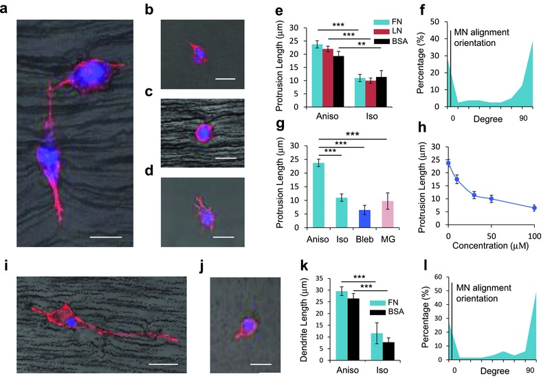
Anisotropic architecture is able to guide the dendrite extension of NIH 3T3 fibroblasts and PC12 cells. Dendritic protrusion of fibroblasts in a) anisotropic matrix, b) isotropic matrix, c) anisotropic matrix treated with 100 × 10−6 m of Blebbistatin (Bleb) composed of fibronectin (FN)‐coated magnetic particles, and d) Matrigel. e) Comparison of protrusion length of fibroblasts grown in anisotropic and isotropic topography composed of FN, laminin (LN), and bovine serum albumin (BSA)‐coated particles. f) Distribution of dendrite orientations in anisotropic matrix composed of FN‐coated particles. The dendrite orientation represents the angle between extended dendrite and the particle chain. g) Comparison of protrusion length of fibroblasts grown in anisotropic, isotropic, bleb‐treated matrices, and Matrigel. h) Change of protrusion length of fibroblasts according to the Bleb concentration. Dendritic protrusion of PC12 cells in i) anisotropic and j) isotropic matrices with FN‐coated particles. k) Comparison of protrusion length of fibroblasts grown in anisotropic and isotropic topography composed of FN, LN, and BSA‐coated particles. l) Distribution of dendrite orientations in anisotropic matrix composed of FN‐coated particles. Scale bars, 20 μm. (Each bar represents 30–50 cases obtained from three samples. Error bars show standard errors. ***p < 0.005, **p < 0.01.)
In this report, we describe a new method to provide topographical and chemical cues to cells in 3D scaffolds. To achieve this, we chemically immobilized the proteins on the surface of magnetic particles, assembled these building blocks using magnetic‐field‐directed self‐assembly in a 3D matrix, and solidified the matrix to maintain the programmed topography. Using this simple technique, we demonstrated diverse topographic patterns independent of other variables that comprise the matrix, such as stiffness or material types, and observed that the anisotropic architecture was able to guide the protrusions of dendritic cells. This process is independent of physicochemical properties of the material, is biocompatible, and provides self‐organized patterns at nano‐ to microscale resolution at low cost. It is also amenable to scaling to high‐volume manufacturing. Using this method, we observed that cells aligned with the direction of the nanofibers independent of the ECM composition, suggesting that topography may be one of the physical cues that is sufficient to override biochemical cues. We believe that this technology could be used to construct nano–bio interfaces for various biomedical engineering applications as well as to continue to dissect the role of topography from other physical cues in in vitro cell culture models.
Experimental Section
Cell Culture: NIH 3T3 fibroblasts were cultured in 75T flasks. The complete growth media contained 10% FBS, 1% p/s, and 1% l‐glutamine and serum‐free medium contained only 1% p/s and 1% l‐glutamine in DMEM. PC12 cells were purchased from ATCC (CRL‐1721) and cultured in collagen‐coated 75T flasks. The complete growth medium contained 10% horse serum, 5% FBS, 1% Pen‐Strep, and 1% l‐glutamine in DMEM. For both cell types, once cells were ≈80% confluent, the complete growth media was aspirated off and 10 mL of fresh complete medium was added back. The differentiating medium contained 1% horse serum, 1% Pen‐Strep, and 100 ng mL−1 neural growth factor (7S‐NGF, Catalog No. N0513, Sigma). In the engineered matrix, fibroblasts were grown in serum‐free medium and PC12 cells were grown in differentiating medium.
Bulk Stiffness Measurement: Bulk rheology measurements were carried out at the Georgetown University Institute for Soft Matter Synthesis and Metrology using an Anton Paar Physica MCR 301 rheometer equipped with a PP‐25 measuring plate (parallel, 25 mm diameter). The Matrigel samples were prepared by pipetting 450 μL of matrix solution (stock Matrigel or Matrigel mixed with ECM‐coated magnetic particles) on Willco wells (GWSB‐5040) containing a 25 mm ID steel washer (1 mm thick), and spreading the solution to cover the washer. The samples were then incubated at 37 °C, in 5% CO2 for 30 min. 3 mL of PBS was added to the samples and they were incubated at room temperature overnight. The next day, PBS was aspirated and the bulk stiffness was measured. First, the top parallel plate was lowered to contact the surface of each sample until a load of 0.2 N was achieved. Frequency sweeps (0.1–10 Hz, 5 points decade−1) were then conducted at 1% strains. Measurements were carried out in triplicate.
Fluorescence Recovery after Photobleaching Measurement: FRAP analysis was conducted using a Zeiss 780 LSM, using Zen software for data acquisition. Fluorescein isothiocyanate–dextrans (wt. 150 000 Da, Sigma Aldrich, FD150S), as fluorescent probes, were mixed with the protein‐coated particles and Matrigel and various nanofibril architectures were fabricated to produce samples. The samples were mounted in eight‐well plates for analysis. A 488 nm laser was applied to the sample for 10 s in three independent circular areas for bleaching and the fluorescence intensities of these areas were observed for 60 s by taking snapshots every 2 s. The images were acquired using a 10× air objective of 0.3 NA.
Protein Conjugation on Superparamagnetic Beads: Carboxyl‐superparamagnetic beads with a diameter of 300 nm with 2.0 g cm−3 of initial density (Max CV 20%) (Adem Tech, catalog number 02131) were used. Iron oxide content in a particle is ≈70% and a single particle has ≈40 emu g−1 of saturation magnetization. The specific surface area of a bead is 15 m2 g−1 and 350 μmol g−1 of carboxyl group covers it. 50 μL of mg mL−1 particles was transferred into the tube and washed twice with 100 μL of activation buffer (Adem Tech, Catalog No. 02820) using magnetic separation. Then 4 mg mL−1 of EDC (M w 191.7, Adem Tech, Catalog No. 02820) solution in activation buffer was prepared and 100 μL of EDC solution was added per 100 μL of particles. This solution was incubated for 1 h at room temperature with shaking. 20 μL of protein (1 mg mL−1) was added to the activated particles and the solution was incubated overnight at room temperature with shaking. 200 μL of BSA solution in an activation buffer (0.5 mg mL−1) was added to the protein‐coated particles and incubated at room temperature for 1 h with shaking. The resulting solution was washed with the storage buffer (Adem Tech, Catalog No. 20820) twice and resuspended to yield a final concentration of 1 mg mL−1.
Preparation of Engineered Matrix: Eight‐well plates were coated with 20 μL of Matrigel (Corning, No. 354230, Lot No. 30032578) and incubated at 37 °C for 4 min. 10 μL of protein‐coated beads (1 mg mL−1) was mixed with 100 μL of Matrigel and 200 000 target cells per mL in the sample. The number of beads was controlled to regulate the final concentration of beads in the matrix. This mixture was homogenized by pipetting several times on ice and then placed on Matrigel‐coated substrate. Isotropic distribution of beads was achieved by solidifying the sample in this step at 37 °C for 25 min. To fabricate an anisotropic architecture, the sample was placed on a magnet. The magnet is NdFeB magnet (K&J Magnetics, Inc., Catalog No. BX8×8×8) whose dimension is 25.4 mm × 25.4 mm × 25.4 mm. The samples were spaced 1 mm or 1 cm apart from the surface of the magnet, and their magnetic field intensities were 4328 and 536 G, respectively. They were measured using a gaussmeter (455 DSP Gaussmeter, Lakeshore) and averaged from ten sampling cases. The assembling process was conducted on ice because Matrigel remains in a liquid state only at low temperatures (2–8 °C). Then the sample was incubated at 37 °C for 25 min for matrix solidification. Hyaluronan was purchased at ESI BIO (Hystem No. GS311). The process for matrix fabrication was the same as used for Matrigel.
Fluorescence Staining: FN was fluorescently labeled with HiLyte 488 (Cytoskeleton Inc., Catalog No. FNR02). LN was fluorescently labeled with Rhodamine (Cytoskeleton Inc., Catalog No. LMN01). NIH 3T3 fibroblasts in the engineered matrix were incubated 12 h, briefly washed with PBS twice, and then fixed in 4% paraformaldehyde overnight. Next, the sample was blocked for 30 min with 1% BSA/PBS solution and then incubated with 1:50 Phalloidin conjugated to Alexa Fluor 633 (Life Technologies, Catalog No. A22284) and 1:500 Hoechst 33342 (Invitrogen, M w 615.99, Catalog No. H3570) for 3 h at room temperature. The sample was subsequently washed three times in PBS. PC12 cells in the engineered matrix were incubated for 2 d, following the same procedure used with NIH 3T3 fibroblasts.
Confocal Microscopy Imaging: Confocal images were acquired using a Zeiss 780 LSM, using Zen software for data acquisition. The samples were mounted in eight‐well plates for snapshot imaging or time‐lapse imaging to monitor the cells. Z stacks were acquired using a tiled approach and a 10× air objective of 0.3 NA, with each individual image comprising 2046 pixels × 2046 pixels corresponding to 1416 μm × 1416 μm, for a total z distance of 276 μm.
Image Analysis: ImageJ and MATLAB programs were used for cell image analysis and matrix analysis. To measure the dendrite lengths and orientations of cells, LSM files were exported to ImageJ and analyzed using ImageJ tools. To analyze the angle of dendrite orientation, the axis of a dendrite was defined as a straight line that connects the middle of cell body and the end of extended dendrite. Then, the dendrite protrusion angle was defined as the angle between the particle chain direction and the dendrite axis. For matrix analysis, LSM files were exported to ImageJ, binarized (the 75th percentile of the intensity histogram was chosen as the threshold for each image) and segmented (Watershed). The binarized images were also exported to MATLAB for box counting analysis using the function to determine the lacunarity. Binarized images were also processed using the CT‐FIRE (Ver. 1.3 Beta 2) curvelet transform fiber extraction software in MATLAB36 to determine the distributions of fiber lengths and widths. All data were plotted using Excel for further statistical analysis.
Supporting information
As a service to our authors and readers, this journal provides supporting information supplied by the authors. Such materials are peer reviewed and may be re‐organized for online delivery, but are not copy‐edited or typeset. Technical support issues arising from supporting information (other than missing files) should be addressed to the authors.
Supplementary
Acknowledgements
This research was supported by the Intramural Research Program of the National Institutes of Health, the National Cancer Institute. The work was also supported by a grant of the Korea Health Technology R&D Project through the Korea Health Industry Development Institute (KHIDI), funded by the Ministry of Health & Welfare, Republic of Korea (Grant No. HI14C1161). The authors thank George Leiman for critically reading this paper.
References
- 1. Mouw J. K., Ou G., Weaver V. M., Nat. Rev. Mol. Cell Biol. 2014, 15, 771. [DOI] [PMC free article] [PubMed] [Google Scholar]
- 2. Chaudhuri O., Gu L., Darnell M., Klumpers D., Bencherif S. A., Weaver J. C., Huebsch N., Mooney D. J., Nat. Commun. 2015, 6, 6364. [DOI] [PMC free article] [PubMed] [Google Scholar]
- 3. Dalby M. J., Gadegaard N., Oreffo R. O. C., Nat. Mater. 2014, 13, 558. [DOI] [PubMed] [Google Scholar]
- 4. Hoffman B. D., Grashoff C., Schwartz M. A., Nature 2011, 475, 316. [DOI] [PMC free article] [PubMed] [Google Scholar]
- 5. Hoffman‐Kim D., Mitchel J. A., Bellamkonda R. V., Annu. Rev. Biomed. Eng. 2010, 12, 203. [DOI] [PMC free article] [PubMed] [Google Scholar]
- 6. Humphrey J. D., Dufresne E. R., Schwartz M. A., Nat. Rev. Mol. Cell Biol. 2014, 15, 802. [DOI] [PMC free article] [PubMed] [Google Scholar]
- 7. Ventre M., Natale C. F., Rianna C., Netti P. A., J. R. Soc. Interface 2014, 11, 20140687. [DOI] [PMC free article] [PubMed] [Google Scholar]
- 8. Griffith L. G., Swartz M. A., Nat. Rev. Mol. Cell Biol. 2006, 7, 211. [DOI] [PubMed] [Google Scholar]
- 9. Bonnans C., Chou J., Werb Z., Nat. Rev. Mol. Cell Biol. 2014, 15, 786. [DOI] [PMC free article] [PubMed] [Google Scholar]
- 10. Kim D. H., Provenzano P. P., Smith C. L., Levchenko A., J. Cell Biol. 2012, 197, 351. [DOI] [PMC free article] [PubMed] [Google Scholar]
- 11. Tanner K., Mori H., Mroue R., Bruni‐Cardoso A., Bissell M. J., Proc. Natl. Acad. Sci. USA 2012, 109, 1973. [DOI] [PMC free article] [PubMed] [Google Scholar]
- 12. Wang H., Lacoche S., Huang L., Xue B., Muthuswamy S. K., Proc. Natl. Acad. Sci. USA 2013, 110, 163. [DOI] [PMC free article] [PubMed] [Google Scholar]
- 13. Doyle A. D., Petrie R. J., Kutys M. L., Yamada K. M., Curr. Opin. Cell Biol. 2013, 25, 642. [DOI] [PMC free article] [PubMed] [Google Scholar]
- 14. Raub C. B., Unruh J., Suresh V., Krasieva T., Lindmo T., Gratton E., Tromberg B. J., Geroge S. C., Biophys. J. 2008, 94, 2361. [DOI] [PMC free article] [PubMed] [Google Scholar]
- 15. Raub C. B., Suresh V., Krasieva T., Lyubovitsky J., Mih J. D., Putnam A. J., Tromberg B. J., George S. C., Biophys. J. 2007, 92, 2212. [DOI] [PMC free article] [PubMed] [Google Scholar]
- 16. Levental K. R., Yu H., Kass L., Lakins J. N., Egeblad M., Erler J. T., Fong S. F., Csiszar K., Giaccia A., Weninger W., Yamauchi M., Gasser D. L., Weaver V. M., Cell 2009, 139, 891. [DOI] [PMC free article] [PubMed] [Google Scholar]
- 17. Dvir T., Timko B. P., Kohane D. S., Langer R., Nat. Nanotechnol. 2011, 6, 13. [DOI] [PMC free article] [PubMed] [Google Scholar]
- 18. Santos E., Hernandez R. M., Pedraz J. L., Orive G., Trends Biotechnol. 2012, 30, 331. [DOI] [PubMed] [Google Scholar]
- 19. DeForest C. A., Anseth K. S., Nat. Chem. 2011, 3, 925. [DOI] [PMC free article] [PubMed] [Google Scholar]
- 20. DeForest C. A., Polizzotti B. D., Anseth K. S., Nat. Mater. 2009, 8, 659. [DOI] [PMC free article] [PubMed] [Google Scholar]
- 21. DeForest C. A., Tirrell D. A., Nat. Mater. 2015, 14, 523. [DOI] [PubMed] [Google Scholar]
- 22. Dong B., Smith M. E., Wnek G. E., Small 2009, 5, 1508. [DOI] [PubMed] [Google Scholar]
- 23. Ionescu L. C., Lee G. C., Sennett B. J., Burdick J. A., Mauck R. L., Biomaterials 2010, 31, 4113. [DOI] [PMC free article] [PubMed] [Google Scholar]
- 24. Ahn S., Deravi L. F., Park S. J., Dabiri B. E., Kim J. S., Parker K. K., Shin K., Adv. Mater. 2015, 27, 2838. [DOI] [PubMed] [Google Scholar]
- 25. Hartgerink J. D., Beniash E., Stupp S. I., Science 2001, 294, 1684. [DOI] [PubMed] [Google Scholar]
- 26. Rexeisen E. L., Fan W., Pangburn T. O., Taribagil R. R., Bates F. S., Lodge T. P., Tsapatsis M., Kokkoli E., Langmuir 2010, 26, 1953. [DOI] [PubMed] [Google Scholar]
- 27. Sur S., Pashuck E. T., Guler M. O., Ito M., Stupp S. I., Launey T., Biomaterials 2012, 33, 545. [DOI] [PMC free article] [PubMed] [Google Scholar]
- 28. Charras G., Sahai E., Nat. Rev. Mol. Cell Biol. 2014, 15, 813. [DOI] [PubMed] [Google Scholar]
- 29. Li Z., Gong Y. W., Sun S. J., Du Y., Lu D. Y., Liu X. F., Long M., Biomaterials 2013, 34, 7616. [DOI] [PubMed] [Google Scholar]
- 30. Watt F. M., Huck W. T. S., Nat. Rev. Mol. Cell Biol. 2013, 14, 467. [DOI] [PubMed] [Google Scholar]
- 31. Conde J., Dias J. T., Grazu V., Moros M., Baptista P. V., de la Fuente J. M., Front. Chem. 2014, 2, 48. [DOI] [PMC free article] [PubMed] [Google Scholar]
- 32. Grzelczak M., Vermant J., Furst E. M., Liz‐Marzan L. M., ACS Nano 2010, 4, 3591. [DOI] [PubMed] [Google Scholar]
- 33. Nie Z. H., Petukhova A., Kumacheva E., Nat. Nanotechnol. 2010, 5, 15. [DOI] [PubMed] [Google Scholar]
- 34. Velev O. D., Gupta S., Adv. Mater. 2009, 21, 1897. [Google Scholar]
- 35. Li J. Y., Ho Y. C., Chung Y. C., Lin F. C., Liao W. L., Tsai W. B., Biofabrication 2013, 5, 035003. [DOI] [PubMed] [Google Scholar]
- 36. Bredfeldt J. S., Liu Y. M., Pehlke C. A., Conklin M. W., Szulczewski J. M., Inman D. R., Keely P. J., Nowak R. D., Mackie T. R., Eliceiri K. W., J. Biomed. Opt. 2014, 19, 16007. [DOI] [PMC free article] [PubMed] [Google Scholar]
Associated Data
This section collects any data citations, data availability statements, or supplementary materials included in this article.
Supplementary Materials
As a service to our authors and readers, this journal provides supporting information supplied by the authors. Such materials are peer reviewed and may be re‐organized for online delivery, but are not copy‐edited or typeset. Technical support issues arising from supporting information (other than missing files) should be addressed to the authors.
Supplementary