Abstract
Transcaval, or caval-aortic, access is a promising approach for fully percutaneous trans-catheter aortic valve implantation in patients without good conventional access options. This tutorial review provides step-by-step guidance to planning and executing the procedure, along with approaches to remedy complications.
Keywords: structural heart disease, alternative access routes, caval-aortic access, nontransfemoral access
INTRODUCTION
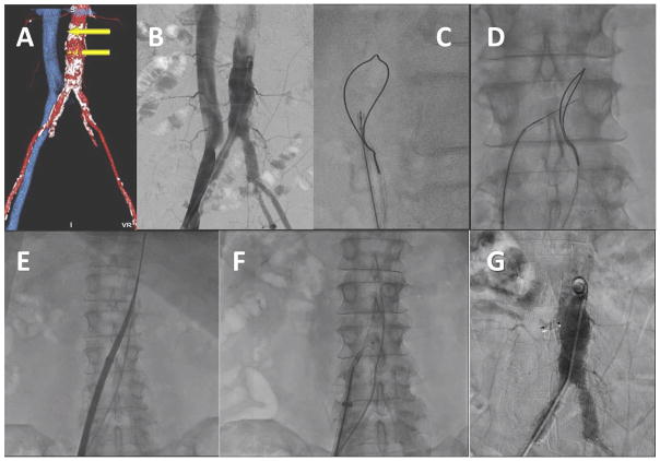
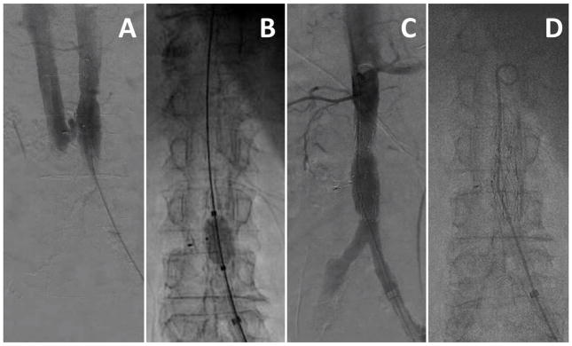
In transcaval acces procedures, the transcatheter aortic valve implantation (TAVI) introducer sheath is advanced from the femoral vein through the inferior vena cava into the adjoining infrarenal abdominal aorta at a preselected target site (Fig. 1). The TAVI procedure is largely unaffected. When the introducer sheath is removed, the caval-aortic access tract is closed by implanting a nitinol occluder device. A key pathophysiologic observation is that a patent hole in the vena cava serves to decompress aortic bleeding, presumably, because the surrounding retroperitoneal space pressurizes and shunts blood into the venous space (Fig. 2). To date, transcaval TAVI has been performed in over 120 patients at 17 medical centers.
Fig. 1.
Video 1. Overview of transcaval access and closure. A: CT-based procedure plan to select a target. B: Simultaneous aortic and caval angiography. C and D: A caval-aortic crossing system viewed in orthogonal projections with an aortic snare serving as a “bulls-eye” target. E: The transcatheter heart valve introducer is advanced from the femoral vein into the aorta. F: After TAVI, a nitinol cardiac occluder device is positioned across the caval-aortic access tract. G: A completion aortagram showing, in this case, complete occlusion of the access tract. [Color figure can be viewed in the online issue, which is available at wileyonlinelibrary.com.]
Fig. 2.
Pathophysiology of iatrogenic abdominal aorto-caval fistula. A: Intuition predicts exsanguination through an aortic rent. B: The observation is that retroperitoneal pressure quickly exceeds venous pressure, causing blood return through the corresponding venous hole. [Color figure can be viewed in the online issue, which is available at wileyonlinelibrary.com.]
In the first reported human case series [1], the procedure was well tolerated even in a cohort of elderly patients deemed unsuitable for transfemoral, transapical, or transaortic TAVI. Bleeding requiring transfusion was common, and covered stents were implanted in approximately one-fifth. Residual aorto-caval fistulae were common, usually well tolerated, and tended to occlude over days to weeks. With further experience and technical refinement, both bleeding and need for covered stents appear reduced. This article details this technique of transcaval access and closure gleaned from personal experience having performed or proctored most cases to date.
New transcaval operators are cautioned not to undertake this procedure without seeking proctorship and participation in ongoing research protocols.
The procedure has several key stages: planning, setup, crossing, TAVI, closure, review for completion, predischarge management, and follow-up surveillance.
PLANNING
Case selection for transcaval access involves the multidisciplinary heart team. At present, transcaval access is offered to patients who are not eligible for femoral artery access and who do not have good alternative access options.
Planning includes careful analysis of a pre-procedure contrast-enhanced abdomen and pelvis CT with thin-slice reconstructions, ideally during the same contrast exposure used to plan the TAVI procedure. The CT is analyzed to identify a suitable calcium-free target near the cava; without interposed structures such as bowel, safely away from renal artery, renal vein, and the aorto-iliac bifurcation in case covered stent is required; and sufficiently close to the femoral vein puncture site that the intended 35–40 cm introducer sheath will reach, as described previously [2]. Ectatic or even grafted aortic targets appear suitable [3]. A representative plan is shown in Fig. 3 and Video 3.
Fig. 3.
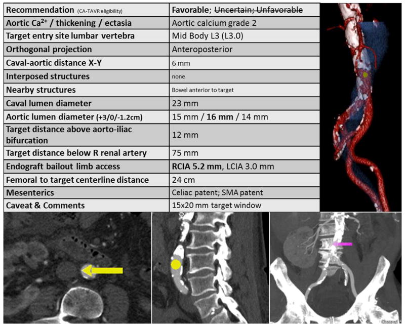
Video 3. A representative CT-based transcaval plan. The table provides guidance. A: En face surface-rendered view of the aorta (red) viewed from the cava (blue) depicting the calcium-free target (yellow dot). B: The suggested target viewed in an axial view. C and D: axial thin and coronal thick views, respectively, depict the target in the context of the lumbar vertebra for operator registration with X-ray fluoroscopy. [Color figure can be viewed in the online issue, which is available at wileyonlinelibrary.com.]
Transcaval access has been performed ad hoc, at experienced centers, during the same session as failed transfemoral artery access, and for emergency TAVI after failed balloon aortic valvuloplasty. Transcaval TAVI has been planned on noncontrast CT, at risk of missing aortic dissection or other intraluminal pathology.
Planning also includes assembly of all devices known to be helpful for the procedure, including crossing equipment, closure devices, catheters for balloon aortic tamponade, and suitable covered stents in case they are needed.
SETUP, INITIAL ACCESS, AND ANGIOGRAPHY
The electrosurgery ground/return pad is attached to the patient before sterile preparation, with care to avoid electrical coupling with other conductive structures such as pacemakers and metallic (hip) implants. The electro-surgery pencil is set to “pure” (rather than blended) cutting mode, with energy typically set to 50 W. Typically, electrosurgery pencils “cut” using the yellow button.
The procedure is usually performed under general anesthesia. Three vascular access sites are necessary. (1) Arterial access (femoral or upper extremity) for aortography, for snaring and tensioning the transcaval guide-wire, and for TAVI-related aortography. The larger femoral vessel is preferable because it allows for immediate bail-out aortic-balloon tamponade and provisional covered stent placement if necessary. If both have equal caliber, the left femoral artery is preferred because it eases manipulation of the aortic snare-target. (2) Venous access for temporary pacing for the TAVI. (3) Right femoral vein access for transcaval heart valve delivery. The procedure is always performed from the right femoral vein.
The right femoral vein is “preclosed” with two suture mediate closure devices (Perclose Proglide, Abbot) and leave a 8Fr short femoral sheath in place for venography. Manual hemostasis or “figure-of-eight” closure are reasonable alternatives [4–6].
Digital subtraction aortography and cavography are performed simultaneously at a typical magnification of ~32 cm (Fig. 4). The projection angle is selected from the CTA-based treatment plan. A marker pigtail is positioned below the renal arteries but above the intended target using lumbar vertebrae as a reference. Aortography uses 10–20 mL over one second into the aorta, and 10–20 mL of 50% diluted contrast via hand injection into the right femoral vein or a pigtail catheter in the IVC. Ventilation is suspended and aortic and caval injections are simultaneous; a common error is to inject the vein too late. It is valuable to continue angiography until renal veins are visualized. “Partial landmarking” or native imaging can depict a roadmap of the crossing target in the context of lumbar vertebrae and stored as a reference. Noncontrast unsubtracted cineangiography can also be helpful during respiration to depict aortic calcification.
Fig. 4.
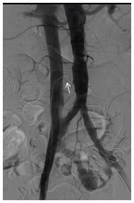
Video 4. Simultaneous aortography and venography with a guiding catheter (arrow) pre-positioned in the cava.
It can be helpful to preposition the caval guiding catheter near the target during aortography. Occasionally this displaces the cava closer to the aorta, and indicates that a double-disc (VSD) occluder may be applicable instead of a single-disc (duct) occluder at the conclusion of the procedure.
If there is any doubt that the intended transcaval introducer sheath may not achieve deep transcaval purchase into the aorta, it is helpful to use a catheter to confirm that the skin-to-aorta distance is at least 7 cm shorter than the sheath working length.
CAVAL-AORTIC CROSSING AND SHEATH DELIVERY
Full-dose heparin is administered to achieve an ACT > 250 s once access is obtained and before caval-aortic crossing. Heparin is preferred because it is reversible using protamine, and because it may suppress intravascular thrombus formation during application of radiofrequency ablation energy.
It is convenient to select a TAVI working angle by thoracic aortography of the valve before abdominal aortography and crossing. This allows TAVI to be performed immediately after transcaval access.
A single-loop aortic gooseneck snare (e.g., Amplatz gooseneck, Medtronic) is introduced via a 5–6 Fr guiding catheter (typically JR4) distal to the target site (i.e., cephalad if introduced from below). The snare is selected to be at least 5 mm larger than the aortic lumen diameter at the target site, for example a 20 mm snare is selected for a 14 mm aorta, to enable appropriate positioning. Multihoop snares are not a satisfactory alternative to gooseneck-design snares because they provide ambiguous targets. A standard Tuohy-Borst valved hemostatic adapter prevents blood loss, and the snare-lock is preloaded for easy application.
A coaxial crossing system is prepared (Fig. 5). The key enabling device is a 0.014″:–0.035″:wire convertor (Piggyback 145cm, Vascular Solutions), which is a jacket that expands the outer diameter of the 0.014″:guidewire and that facilitates delivery of the 0.035″:microcatheter into the aorta. A 300 cm rigid-tip coronary CTO guidewire (for example, Confienza Pro 12, Asahi) is backloaded to extend antegrade beyond a long Piggyback wire convertor and then both are advanced into a 90cm braided 0.035” microcatheter (for example Navicross, Terumo; CXI, Cook; QuickCross Extreme, Spectranetics; Minnie, Vascular Solutions), shorter than the Piggyback and longer than the guiding catheter. One specific coronary guidewire family has been tested; other devices may have different insulation properties that cause them to perform inadequately. Assure the guide-wire is wiped clean so that it can advance freely within the Piggyback. At this point, the distal 10–12 mm of the Confienza is amputated briskly with sterile scissors to increase tip stiffness and straightness, and the tip is discarded. If a kink is introduced into the tip, the Confienza should be discarded and replaced.
Fig. 5.
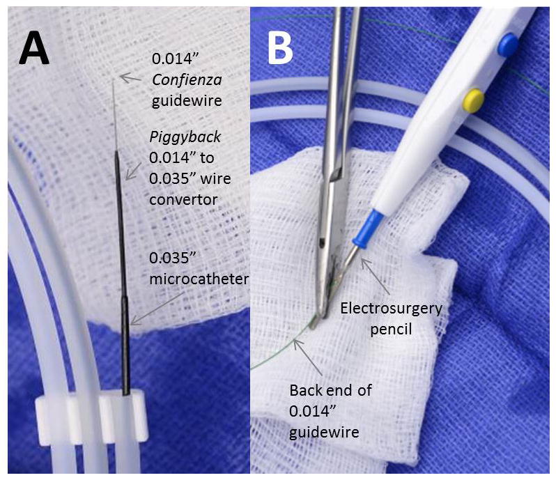
Crossing equipment (1). A: A 0.014″:Confienza guide-wire, with its tip amputated, is inserted through a Piggyback 0.014″:–0.035″:wire convertor, which is inserted inside a 0.035″:braided microcatheter. B: The back end of the guidewire, free of potential short-circuits, is electrically connected to an elec-trosurgery pencil using a clamp. [Color figure can be viewed in the online issue, which is available at wileyonlinelibrary.com.]
A stiff-design 7 Fr renal-curve guiding catheter is positioned in the inferior vena cava over a guidewire a few cm above the intended target. A 7 Fr guiding catheter provides better back-up for crossing than smaller guides or diagnostic catheters. The shape is selected to direct the crossing system horizontally into the aorta. For a cava diameter 20–25 mm, a shorter RDC-1 curve is suitable; for a cava wider than 25 mm an RDC curve; for a cava <20 mm wide, or if any catheter points cephalad instead of orthogonally to the aortic target, a JR4 or IM curve is selected. A spring-loaded Tuohy-Borst adapter (e.g., Co-pilot) allows unconstrained movement of the microcatheter assembly.
With 2–5 mm of the amputated Confienza extending beyond the Piggyback and 2–10 cm of the Piggback extending beyond the microcatheter, the crossing system is advanced to just inside the tip of the renal guide.
The back-end of the Confienza is attached to the electrosurgery pencil using a hemostat or needle-driver. Attention is paid that there are no loops or wet towels that might cause an electrical “short-circuit.”
Next, the equipment is positioned for crossing. The X-ray table is raised to the isocenter position and the C-arm set at the CT-predicted crossing and orthogonal angles. The intended lumbar vertebral reference and aortic calcium reference are identified visually.
The snare + guide system is fine-positioned over the target (Fig. 6). The caval guiding catheter is then fine positioned toward the aortic target and snare. Fine positioning of both is most easily achieved via pull-back to the intended location rather than advancement The X-ray C-arm is then rotated to the orthogonal projection (e.g., LAO 75° if crossing at RAO 15°) to assure the renal guide and wire are pointed at the middle of the aorta and the snare. The renal guide is torqued for further fine positioning. Multiple checks and fine-positioning maneuvers are common in the anteroposterior-like and lateral-like orthogonal projections. Further fine positioning takes into account individual pathology predicted from the CT plan, such as anterior bowel or focal anteroposterior calcification. Biplane X-ray is therefore helpful.
Fig. 6.
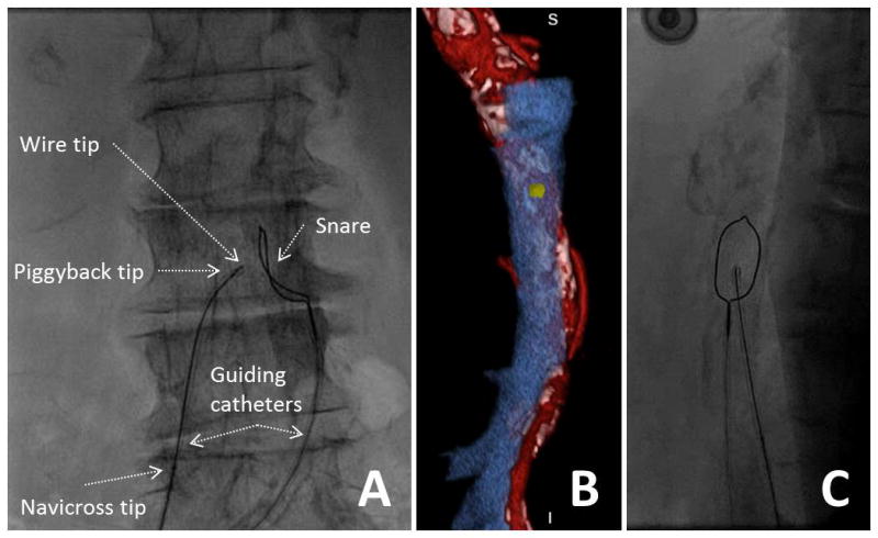
Video 6. Positioning crossing equipment. A: The caval guiding catheter directs the crossing wire and the aortic guiding catheter directs the snare. B: The en face rendering of the aortic target is reviewed and compared to the aorta during fine-positioning (C). [Color figure can be viewed in the online issue, which is available at wileyonlinelibrary.com.]
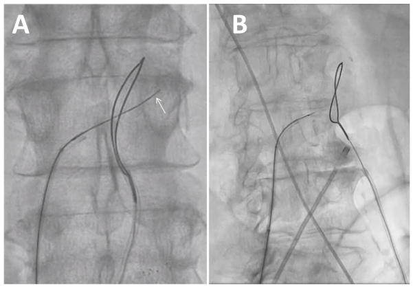
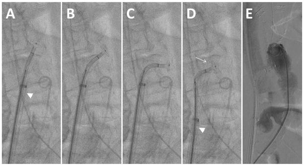
Crossing is performed by assuring the Piggyback is “unlocked” so the guidewire may advance freely. An assistant activates the electrosurgery “cutting” mode while the operator advances the guidewire (Fig. 7). If appropriately positioned and aimed at a calcium-free target, the amputated Confienza typically advances freely. The wire should not be energized for intervals longer than 1–2 sec because charred tissue accumulates on the guidewire, causing heating and not vaporization of target tissue. Failure of the wire to advance easily indicates either (1) calcification at the selected crossing target; (2) char on the tip of the wire; (3) inadequate energy settings or a short-circuit in the electrosurgery-wire assembly. A “fresh” wire that buckles usually requires repositioning toward a confirmed calcium-free window.
Fig. 7.
Video 7. Successful crossing. The wire should pass easily into the aorta, and can be advanced after radiofrequency energy is suspended until it deflects at the contralateral aortic wall (arrow). Buckling of the wire outside the aorta indicates a problem that must be remedied.
Once the wire crosses into the aortic lumen and through the snare, electrosurgery “cutting” should be terminated to avoid perforating the contralateral wall of the aorta. The wire can then be advanced farther past the snare without electrification. Buckling of the non-electrified wire against the left side of the aorta is common and probably desirable (Fig. 7A). Once snared (Fig. 8), assure the captured wire is “locked” onto the snare. The Piggyback is usually left unlocked so that it does not resist advancement of the guidewire into the aorta. In coordination with an assistant, the snare and the guidewire are advanced in tandem into the thoracic aorta (Fig. 8B), near the subclavian artery, followed by advancement of the Piggyback to the wire tip. Next advance the braided microcatheter across the aorta. Snare-counter-traction can be helpful during these steps. If snare-capture is lost before the microcatheter reaches the aorta, a brief attempt to re-snare in the thoracic aorta is usually warranted. Ensuring that the IVC guiding cathter abuts the wall of the IVC and clockwise rotation of the braided microcatheter may facilitate crossing the aortic wall.
Fig. 8.
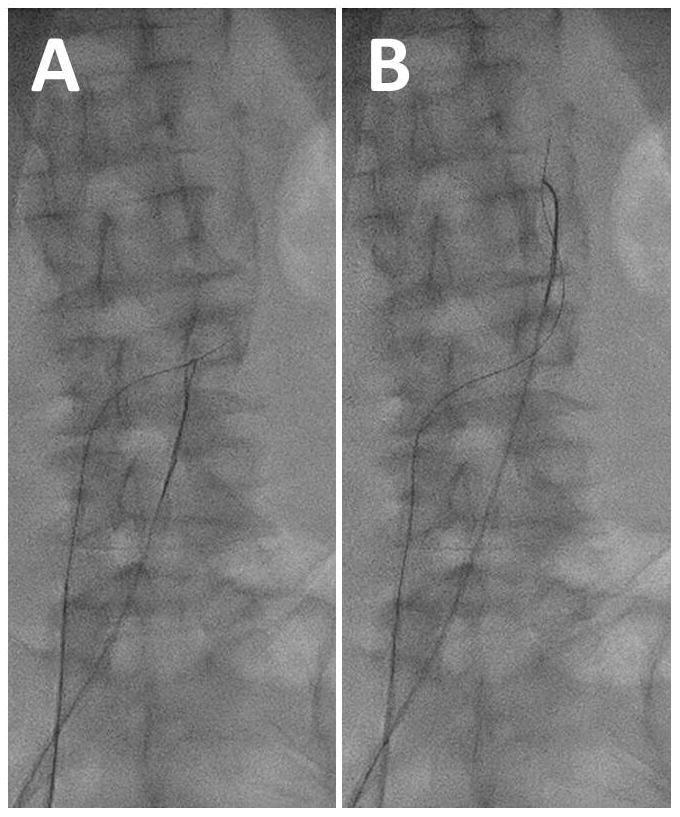
Video 8. Snare application. A: Tighten the snare to capture the guidewire after caval-aortic traversal. B: Advance the guidewire and snare in tandem up to the thoracic aorta.
If despite these efforts, the microcatheter does not cross from the cava into the aorta, the microcatheter and Piggyback are withdrawn, leaving the 0.014″: guidewire across the tract, and a contrast filled 2.0–2.5 mm × 20 mm noncompliant coronary balloon catheter is inflated to high pressure across the aortic wall until the balloon “waist” is eliminated. Despite balloon withdrawal at this stage, the blood pressure remains steady. Both the Piggyback and microcatheter are then reinserted. This allows the Piggyback +microcatheter easily to enter the aorta. Once the microcatheter is in the thoracic descending aorta, the wire is released from the snare and the wire and Piggyback are removed. Infrequently, when even a low-profile coronary balloon fails to cross the caval-aortic tract, a lower-profile microcatheter (Corsair, Asahi, Abbott) enables exchange for a more rigid guidewire (Hi-Torque Spartacore, Abbott) and thereafter successful coronary balloon dilatation followed by Piggyback and microcatheter delivery. With the Corsair in the thoracic aorta, the snare can be temporarily slipped down onto the Corsair for traction while the rigid guidewire is delivered and then re-snared for traction while the Corsair is removed.
After successful crossing with the 0.035″ microcatheter, the snare is removed from the aorta and the arterial guiding catheter is exchanged for a pigtail angiographic catheter to aid TAVI. Next, a Lunderquist extra-stiff guidewire is introduced through the microcatheter from the femoral vein into the aorta. The microcatheter, renal guiding catheter, and venous sheath are then removed. This last step is delayed until immediately before the TAVI sheath is ready to be introduced, to avoid bleeding from the “tented” caval-aortic tract.
The femoral vein skin puncture site is dilated if necessary, for example using a large dilator, taking care not to predilate the transcaval site prematurely.
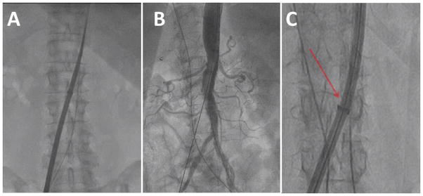
Next, the heart valve introducer sheath is advanced from the femoral vein toward the aorta, in one step without predilatation (Fig. 9). For Edwards Sapien XT or Sapien 3 valves, the selected eSheath is oriented so that the expansion slit enters the aorta first, on the caudal aspect of the tract. This corresponds to the eSheath sidearm pointed directly upwards with the Edwards logo facing rightwards towards the operator. Torque maneuvers should be avoided. The introcedure and dilator are advanced and not withdrawn once crossing begins, because that may cause important bleeding without venous decompression. Take care to observe the tip of the dilator at all times so that it never “overrides” the aortic guidewire. The sheath should be observed carefully with cine as it enters the aorta, especially at the cephalad side. If the sheath tip is observed to “splay” or “flare” as the sheath trailing edge fails to enter the aorta, gentry retract the sheath to relieve the “splay,” which risks aortic laceration and damage to the sheath. Rotating the sheath slightly during another advancement attempt appears helpful. For other valves, nonexpandable introducer sheaths are recommended, having a working length ≥35 cm. Re-constrainable expandable sheaths currently marketed appear unsuitable for transcaval access.
Fig. 9.
Video 9. Sheath advancement. A: Over a Lunderquist guidewire, the heart valve introducer sheath is advanced from the cava into the aorta. B: Sheath arteriograms have shown hemostasis in every case; we no longer obtain these. C: Watch carefully to assure the sheath does not flare (arrow) during advancement, as shown in another patient. [Color figure can be viewed in the online issue, which is available at wileyonlinelibrary.com.]
The sheath is advanced to the 2–3 cm from the hub to skin as long as sheath length allows, and is then sutured securely to the skin to avoid inadvertent retraction, which is hazardous. This 2–3 cm allows tandem advancement of the valve and sheath sheath should there be difficulty advancing the heart valve through the sheath. The sheath is flushed.
Aortography after transcaval sheath access has so far never demonstrated aortic bleeding at this stage, and it therefore is not recommended. Inexperienced operators may nevertheless take comfort in a low-volume contrast aortagram at this stage, using the previously reinserted pig tail catheter placed a few centimeters cephalad to the TAVI sheath .
The femoral vein temporary pacemaker leads are best placed after the TAVI delivery sheath to avoid dislodgement; balloon deflation may facilitate advancement past the TAVI sheath. If placed before the trans-caval sheath, pacemaker capture should be verified. Next TAVI is performed as usual.
CLOSING THE AORTO-CAVAL TRACT
The caval-aortic access tract is closed using Amplatzer nitinol closure devices, which are not designed for this application and are usually not immediately hemostatic. The closure procedure has three phases: (1) Prepare by assembling equipment and reversing anticoagulation; (2) Close; (3) Review angiography, remedy complications, and conclude.
Preparing to Close
Heparin anticoagulation should be reversed fully with protamine before closure begins, to enhance hemostasis. There also appears to be value in correcting other coagulopathies including uremia with plasma and platelets at this step.
Emergency remediation equipment should be assembled in the treatment room. This includes balloons for aortic tamponade, sheaths to allow delivery of these balloons, and appropriately sized aortic covered stents. These are described below.
Closure
A soft or medium-stiffness buddy 0.014″ guidewire is advanced into the thoracic aorta through the caval-aortic sheath, introduced using a small dilator to overcome the hemostatic valve. A stiff-shaft guidewire may risk lacerating the aorta.
In case of premature withdrawal of the sheath into the cava, emergency pull-through of the closure device or other failure of the aorto-caval closure requiring retrieval of the closure device, a 4–5 Fr multipurpose catheter, the large caval-aortic sheath dilator, and the Lunderquist wire are kept ready for immediate sheath access. After inadvertent pull-through of the closure device, the multipurpose catheter is advanced over the buddy wire and used to exchange for the Lunderquist, which is used to readvance the large caval-aortic sheath with its dilator back into the aorta. It is important (1) not to advance the caval sheath into the aorta without a dilator, and (2) not to readvance an expanded eSheath but rather to replace with a new sheath (e.g., fresh unused eSheath, Edwards, or Large or Extra-Large Check-Flo 40cm, Cook Medical).
A pigtail catheter is positioned below the crossing site, and after the aortic disc is deployed, the pigtail is advanced cephalad to allow hand angiographic “puffs” during closure. A guidewire is kept ready to help advance the pigtail if there is difficulty advancing it.
The sheath skin sutures are cut. The power injector is reloaded with contrast.
Table I summarizes current guidelines to select a suitable Amplatzer Closure Device. Sizing the Amplatzer device balances two considerations. Undersizing seems to cause inadequate hemostasis, and oversizing causes “pinching” of the aortic transmural segment leading to malapposition of the aortic disc against the aortic wall. If the venous disc of the Muscular VSD Occluder is too short to reach the cava, it probably has little therapeutic value and indeed may increase the risk of premature occlusion of the venous decompression site.
TABLE I.
Current Algorithm to Select a Nitinol Closure Device
| Sheath | > 18Fr ID fully expanded | <= 18Fr ID fully expanded |
|---|---|---|
| Aorto-caval tract length ≥7 mm | 8 mm Amplatzer Muscular VSD Occluder | 6 mm Amplatzer Muscular VSD Occluder |
| Aorto-caval tract length >7 mm | 10/8 Amplatzer Duct Occluder generation 1 | 8/6 Amplatzer Duct Occluder generation 1 |
The Amplatzer Closure Device is mounted on the loading system and flushed appropriately. Deployment is best achieved using a deflectable delivery catheter (Agilis SML curl, St Jude) to help orient the disc perpendicular to the aorta during pullback. This requires amputating the tip of the matching Amplatzer loader to insert into the deflectable catheter.
Confirm the aortic entry site using lumbar vertebral landmarks. The buddy wire is a helpful adjunct.
Position the Amplatzer system to the distal edge of its introducer sheath and advance it just outside the TAVI sheath. Withdraw them in tandem to ½ vertebral space above the aortic entry site. Take care not to withdraw the sheath from the aorta prematurely. Expose the aortic disc of the Amplatzer closure device in the abdominal aorta. Deflect the device horizontally, ensuring enough separation from the introducer sheath to allow deflection to occur. Take care not to injure the abdominal aorta lumen during these maneuvers, since the rigid nitinol discs are often larger than the aorta lumen.
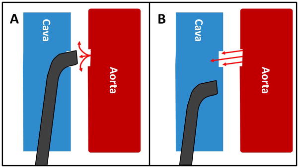
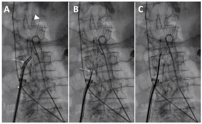
Next, it is time to position the aortic disc. Steadily withdraw the transcaval TAVI introducer sheath completely outside the aorta and well inside the cava. It is important to note that incomplete or partial sheath withdrawal causes heavy bleeding because it blocks venous blood return (depicted in Fig. 10). Using a deflectable sheath, the aortic disc of the nitinol occluder is turned horizontally inside the aorta. This is most easily performed beginning approximately one-half vertebral space above the aorto-caval crossing point after the TAVI sheath is fully withdrawn. The closure system is iteratively deflected, withdrawn a few millimeters, and re-advanced a few millimeters to allow the closure disc to re-orient horizontally.
Fig. 10.
Pathophysiology of inadvertent venous outflow obstruction. A: The introducer sheath is only partially withdrawn out of the aorta into the interstitial retroperitoneal space. Aortic bleeding accumulates in the retroperitoneum. B: The introducer sheath is fully withdrawn out of the aorta into the cava. Now aortic bleeding decompresses into the cava. [Color figure can be viewed in the online issue, which is available at wileyonlinelibrary.com.]
Once the occluder is withdrawn to abut the right aortic wall (Fig. 11 and Video 11), advance the pigtail connector above the aortic entry site while avoiding entrapment, and reconnect to allow contrast injection. A manual contrast puff should demonstrate appropriate disc apposition and usually shows heavy aorto-caval fistulous flow.
Fig. 11.
Video 11. Deploying the aortic disc. A: The aortic disc is passively exposed through the deflectable sheath; the TAVI sheath (arrowhead) remains inside the aorta. B and C: the aortic disc is rotated horizontally by iterative push-and-pull maneuvers while the sheath is deflected. D: The TAVI sheath (arrowhead) is withdrawn outside the aorta and the deflectable sheath retracted to abut the aortic disc against the right aortic endoluminal wall. The buddy wire is evident (arrow). E: The pigtail is advanced cephalad and a hand-injected angiogram performed.
While retaining tension on the aortic disc, further withdraw the delivery catheter in order passively to expose the stretched extra-aortic component (Fig. 12). If using a muscular VSD occluder, the aim is to reach the cava and to “capture” the caval luminal boundary; if using a duct occluder, the aim is only to appose the right aortic wall. Straighten the deflectable delivery catheter while withdrawing from the aorta to lessen undesirable torque on the delivery cable. Finally, advance the delivery cable to re-form the Amplatzer closure device. Occasionally, despite preprocedure planning suggesting that suggests adequate aorto-caval distance for a double-disc occluder, the venous disc of the muscular VSD occluder fails to reach the caval lumen, presumably because of displacement of the cava by intraprocedural hematoma. While there usually is little recourse there also is little consequence.
Fig. 12.
Video 12. Deployment of the neck (for a duct occluder) or venous disc (for a VSD occluder). A: Tension is applied on the occluder cable while the deflectable sheath (arrow) is simultaneously withdrawn and straightened. A buddy wire (arrowhead) and the TAVI introducer withdrawn to the cava (asterisk) are evident. B: the straightened deflectable sheath is fully withdrawn and the cable (arrow) retracted for maximal stretching of the nitinol device. C: The cable is the readvanced to form the venous side of the occluder.
During these maneuvers, the systolic blood pressure often declines, but usually not dramatically unless there is a problem such as significant aortic injury or failure to allow venous decompression by withdrawing the aortic sheath. Once the closure device is positioned, the systolic blood pressure usually returns to baseline rapidly. Urgent blood transfusion is usually not necessary at this stage unless there is prolonged hemodynamic instability.
Perform digital subtraction aortography to assure adequate device position before the cable is released, using a breathhold and using prolonged cineangiography to detect extravasation. If the position appears satisfactory, the delivery cable is released and buddy wire removed. In general, recapture of a device causes injury and should not be undertaken without strong justification such as major maldeployment. If the device needs to be recaptured, prepare the recrossing system to allow rapid exchange for the Lunderquist and re-advancement of the sheath over the original sheath dilator. Recrossing usually requires up-sizing the Amplatzer closure device by 2 mm. Do not forget that expandable sheaths must be replaced before any aortic recrossing maneuver.
Judgment in Concluding the Procedure
The final phase of the transcaval procedure entails review, remedy, and conclusion.
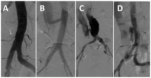
Completion digital subtraction angiography, typically 12–20 mL over 1–2 sec, is performed during breath-hold and continued until contrast wash-out. Typical completion angiography patterns are shown in Fig. 13. Using marketed Amplatzer devices, residual aorto-caval fistula is expected especially when using sheaths having an outer diameter >6 mm. The most common pattern is fistula and contrast flowing within and around the neck of the occluder device in a “cruciform” pattern before returning to the venous space (Fig. 13; panel C).
Fig. 13.
Angiographic patterns of closure. A: complete occlusion around closure device (arrow). B: Patent fistula, in this case, with a long-tunnel around a duct occluder. C: Patent fistula with a “cruciform” contrast flow around the neck of the occluder but with contrast return to the cava. This is the most common immediate pattern. D: Extravasation.
In general, if the occluder device is not malde-ployed, there is no procedural step that requires continued large-bore venous access. Therefore, if there is hemodynamic stability, the right femoral venous access port is closed—using preclose, figure-of-eight, or manual compression techniques—to allow ~10 min to elapse before final aortography.
Assuming there are no complications of TAVI, hemodynamic compromise should it occur at this point is caused either by extravasation or by inability to tolerate the acute arteriovenous shunt because of underlying myocardial dysfunction or pulmonary vascular disease. Immediate management focuses on detecting extravasation, which is not subtle, on the digital subtraction angiogram, or on detecting acute right ventricular failure by echocardiography and/or sudden venous hypertension, which indicates inability to tolerate the shunt.
Mild aortic extravasation usually stops after a few minutes of observation after full protamine reversal of heparinization. Persistent mild extravasation can be managed expectantly with volume or blood infusion and low-dose vasopressors, or alternatively with covered stent deployment (see below). One important cause of mild persistent extravasation is premature occlusion at the venous side, usually by a muscular VSD occluder, before hemostasis at the aortic side. This often subsides immediately but may best be managed with temporary aortic balloon occlusion (see below).
More-than-mild extravasation, or any hemodynamic instability, warrants further invasive management. A good first step is to apply a lower pressure occlusive aortic balloon (e.g., Reliant, Medtronic or Coda, Cook, or an oversized and underinflated angioplasty balloon) for ~5 min, which usually achieves hemostasis (Fig. 14). This can be introduced sheathless if preferred because of small aortoiliac access vessels.
Fig. 14.
Video 14. Management of extravasation with transient aortic balloon occlusion. A: Extravasation with hemodynamic stability after deployment of a muscular VSD occluder. B: A 14mm balloon catheter (arrow) transiently occludes the aorta for two 5-min intervals. Note the delivery cable is detached. C: Extravasation is resolved although there is minor residual aorto-caval fistula at the conclusion of the procedure, followed by occlusion hours later. This patient suffered a retroperitoneal hematoma and required two units of red blood cells, and was discharged four days afterwards.
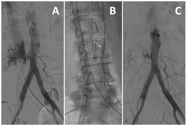
If aortic occlusion fails, or if the extravasation is dramatic, the next step is immediate aortic covered stent implantation (Fig. 15), which recently has been required in ~5% of cases. Self-expanding covered stents designed with outer surface graft material appear preferable (e.g. AFX iliac limb extender, Endologix) because they conform and achieve immediate hemostasis with little or no injurious postdilatation compared with self-expanding designs having an endoluminal graft (e.g., Viabahn, Gore) or with balloon-expandable designs.
Fig. 15.
Video 15. Intolerable fistula requiring endograft. A: Angiography showed brisk residual aorto-caval fistula accompanied by systemic hypotension and venous hypertension attributed to right ventricular shock. B: Transient aortic balloon tamponade immediately restores normal blood pressure but hemodynamic instability recurs after balloon deflation. C: A self-expanding covered nitinol stent is deployed in the aorta. D: The fistula is resolved and hemodynamic stability is restored.
After final angiography, all remaining catheters are removed as per routine and the procedure is concluded. To date, there are not reports of any case in which angiographic patterns become worse after the conclusion of the procedure.
INPATIENT POSTPROCEDURE CARE
A post-procedure strategy of permissive anemia appears successful. Blood transfusions can be avoided except for hemodynamic instability when the hemoglobin is >6—7 g/dL. Low-grade retroperitoneal bleeding can be managed conservatively overnight, including volume and even low-dose vasopressors. Volume is infused liberally as prophylaxis against contrast nephropathy. Aspirin, clopidogrel, and anticoagulation are resumed according to institutional routine.
“Unscheduled” CTA is not obtained unless there is a clear clinical suspicion of ongoing retroperitoneal bleeding. A routine contrast-enhanced CT, arterial-phase, is important to obtain of the abdomen before discharge, in order to assess the caval closure site, aorto-caval fistula patency, and iatrogenic aortic injury. If contrast is not possible, a noncontrast MRI is obtained, or at least a noncontrast CT. These are valuable even if the patient has previous demonstration of occluded aorto-caval tract or even after aortic covered stent.
A small proportion of patients develop thrombocytopenia, sometimes severe and typically asymptomatic, that is ascribed to mechanical platelet injury from the aorto-caval fistula and which appears to subside after spontaneous fistula closure. Nevertheless, patients should be evaluated and treated for heparin induced thrombocytopenia according to clinical judgment.
POSTDISCHARGE CARE AND SURVEILLANCE
Follow-up arterial-phase contrast-enhanced CT angiography of the abdomen and pelvis should be obtained in all patients at both 1- and 12-months after the procedure. These are to assess for vascular or extravascular injury related to the transcaval procedure, to assure closure of small pseudo-aneurysm-like pockets surrounding the closure device, and to assure late closure of the fistulae. To date there are no reports of any late sequelae of transcaval access and closure.
CONCLUSION
Transcaval access is a new technique to enable fully percutaneous TAVI in patients without adequate femoral artery access. Satisfactory closure is obtained in the majority of patients despite using nitinol occluder devices that are not designed for this application and that are not immediately hemostatic. Adjunctive aortic balloon tamponade or covered stent implantation has sufficed for all other cases. To our knowledge there have been no surgical repairs or deaths directly attributable to transcaval access despite its application to high risk patients without other good access options.
While this review details the steps required for successful transcaval TAVI, it is still no substitute for proctorship and careful investigation during the refinement and adoption of the procedure.
Supplementary Material
Acknowledgments
Contract grant sponsor: Division of Intramural Research; Contract grant number: Z01-HL006040.
Footnotes
CONFLICTS OF INTEREST
ABG has served as a proctor for Edwards Lifesciences, which manufactures transcatheter heart valves, and for St Jude Medical, which manufactures Amplatzer nitinol occluder devices.
VCB is a consultant for Edwards Lifesciences and for Abbott Vascular, and his employer has research contracts for multicenter investigation of TAVI devices from Edwards Lifesciences, Abbott Vascular, Medtronic, St Jude Medical, Boston Scientific.
RJL and ABG are inventors on a patent application, assigned to their employers, on devices to facilitate transcaval closure.
References
- 1.Greenbaum AB, O’Neill WW, Paone G, Guerrero ME, Wyman JF, Cooper RL, Lederman RJ. Caval-aortic access to allow transcatheter aortic valve replacement in otherwise ineligible patients: Initial human experience. J Am Coll Cardiol. 2014;63:2795–804. doi: 10.1016/j.jacc.2014.04.015. [DOI] [PMC free article] [PubMed] [Google Scholar]
- 2.Lederman RJ, Chen MY, Rogers T, Wang DD, Paone G, Guerrero M, O’Neill WW, Greenbaum AB. Planning transcaval access using CT for large transcatheter implants. JACC Cardiovasc Imaging. 2014;7:1167–1171. doi: 10.1016/j.jcmg.2014.05.015. [DOI] [PMC free article] [PubMed] [Google Scholar]
- 3.Lederman RJ, O’Neill WW, Greenbaum AB. Transcaval access for TAVR across a polyester aortic graft. Catheter Cardiovasc Interv. 2015;85:1270–1273. doi: 10.1002/ccd.25781. [DOI] [PMC free article] [PubMed] [Google Scholar]
- 4.Cilingiroglu M, Salinger M, Zhao D, Feldman T. Technique of temporary subcutaneous “Figure-of-Eight” sutures to achieve hemostasis after removal of large-caliber femoral venous sheaths. Catheter Cardiovasc Interv. 2011;78:155–160. doi: 10.1002/ccd.22946. [DOI] [PubMed] [Google Scholar]
- 5.Toggweiler S, Leipsic J, Binder RK, Freeman M, Barbanti M, Heijmen RH, Wood DA, Webb JG. Management of vascular access in transcatheter aortic valve replacement: Part 1: Basic anatomy, imaging, sheaths, wires, and access routes. JACC Cardiovasc Interv. 2013;6:643–653. doi: 10.1016/j.jcin.2013.04.003. [DOI] [PubMed] [Google Scholar]
- 6.Geis NA, Pleger ST, Chorianopoulos E, Muller OJ, Katus HA, Bekeredjian R. Feasibility and clinical benefit of a suture-mediated closure device for femoral vein access after percutaneous edge-to-edge mitral valve repair. EuroIntervention. 2015;10:1346–1353. doi: 10.4244/EIJV10I11A231. [DOI] [PubMed] [Google Scholar]
Associated Data
This section collects any data citations, data availability statements, or supplementary materials included in this article.


