Abstract
Objective:
The purpose of this study was to develop size-based radiotherapy kilovoltage cone beam CT (CBCT) protocols for the pelvis.
Methods:
Image noise was measured in an elliptical phantom of varying size for a range of exposure factors. Based on a previously defined “small pelvis” reference patient and CBCT protocol, appropriate exposure factors for small, medium, large and extra-large patients were derived which approximate the image noise behaviour observed on a Philips CT scanner (Philips Medical Systems, Best, Netherlands) with automatic exposure control (AEC). Selection criteria, based on maximum tube current–time product per rotation selected during the radiotherapy treatment planning scan, were derived based on an audit of patient size.
Results:
It has been demonstrated that 110 kVp yields acceptable image noise for reduced patient dose in pelvic CBCT scans of small, medium and large patients, when compared with manufacturer's default settings (125 kVp). Conversely, extra-large patients require increased exposure factors to give acceptable images. 57% of patients in the local population now receive much lower radiation doses, whereas 13% require higher doses (but now yield acceptable images).
Conclusion:
The implementation of size-based exposure protocols has significantly reduced radiation dose to the majority of patients with no negative impact on image quality. Increased doses are required on the largest patients to give adequate image quality.
Advances in knowledge:
The development of size-based CBCT protocols that use the planning CT scan (with AEC) to determine which protocol is appropriate ensures adequate image quality whilst minimizing patient radiation dose.
INTRODUCTION
The introduction of cone beam CT (CBCT) imaging capabilities on radiotherapy treatment systems has led to rapid developments in the field of image-guided radiotherapy. The enhanced visualization of patients' anatomy in three dimensions allows improved positional accuracy for increasingly complex treatments1–7 and is considered essential in the development of adaptive radiotherapy techniques, where the treatment may be adjusted and tailored to each individual patient's needs as a result of changes that are observed in their anatomy.8–11
With the benefits that CBCT offers, it is important to ensure that it is used in the most effective way. This is particularly important given the magnitude of the associated radiation dose that the patient will be subjected to, when, for example, CBCT imaging is used at least once during every fraction of treatment, with repeats occasionally required owing to the issues with patient set-up. A number of studies in the literature12–25 have reported that typical organ doses in excess of 1 Gy can be associated with this type of intensive imaging regime. It is therefore essential to ensure that the benefits of the exposure (e.g. improved treatment outcome and/or reduced treatment margins through improved localization) outweigh the risks (e.g. radiation-induced malignancies or deterministic effects). This process of justification is one of the fundamental principles of radiation protection.26
Furthermore, having justified a CBCT examination for an individual patient, it is essential to ensure that the exposure is optimized to ensure that radiation doses are “As Low As Reasonably Practicable, consistent with the intended purpose”. This process of optimization in imaging is often misrepresented to imply that exposure factors should be reduced to the lowest possible level to give minimal dose to the patient with no consideration of other factors. However, it is essential in all optimization work to consider the clinical task at hand to make sure that image quality is not compromised to the point where the images proffer no benefit to the radiotherapy treatment and hence can no longer be justified. Perversely, reducing doses to this point may mean that overall radiation dose to the patient actually increases given the risk of repeated imaging. The requirements to ensure each exposure of ionizing radiation is both justified and optimized is enshrined in UK law through the Ionising Radiation (Medical Exposure) Regulations 2000.27
The quantification of radiation dose for patients undergoing CBCT exposures has been covered extensively in the literature,12–24 with a wide range of techniques used to either calculate or measure relevant quantities. These include measurements in cylindrical polymethyl methacrylate phantoms, point dosemeters in anthropomorphic phantoms, calculations with mathematical phantoms and individualized patient dose estimation through Monte Carlo techniques. However, whilst these studies demonstrate the level of dose that the patient is subjected to, for the most part, they only consider the manufacturer's default exposure settings that are often limited to a single protocol for each anatomical site (e.g. “pelvis”). This approach to CBCT imaging cannot be considered optimized as it does not take into account the size of the patient and therefore the effect that this has on both patient dose and image quality. With a single set of exposure factors, it is likely that imaging doses are too high for individuals who are very slim, whereas image quality may not be fit for purpose with the largest patients. With modern multislice CT scanners, this issue has been partly addressed with the introduction of automatic exposure control (AEC) systems, which aim to optimize individual exposures by varying the tube current (mA) throughout the scan based on the attenuation properties of the patient,28–31 i.e. larger patients or more attenuating regions use a higher mA to ensure adequate image quality, whereas less attenuation allows lower mA to be used. However, such technology is not yet available on the linear accelerator-based CBCT imaging system that is the subject of this study; therefore, an alternative solution for compensating for patient size is required.
The purpose of this study was to develop a strategy for the optimization of patient dose and image quality for the Varian On-Board-Imager system (OBI; Varian® Medical Systems, Palo Alto, CA) through the introduction of patient size-specific exposure protocols for pelvic imaging. The motivation for this work followed on from the optimization of exposure factors for a small patient who was undergoing daily pelvic CBCT imaging as part of their treatment. Both effective dose and individual organ doses were reduced significantly compared with the manufacturer's default protocol by lowering tube accelerating potential to 110 kV and tube current to 40 mA. The resulting image quality was still sufficient for performing the clinical task of matching soft-tissue structures to the original planning CT data (Figure 1).
Figure 1.
Cone beam CT (CBCT) images of (a) a small patient scanned with the manufacturer's default protocol (125 kVp, 80 mA and 13 ms) and (b) the same small patient scanned with “optimized” settings (110 kVp, 40 mA and 13 ms).
METHODS AND MATERIALS
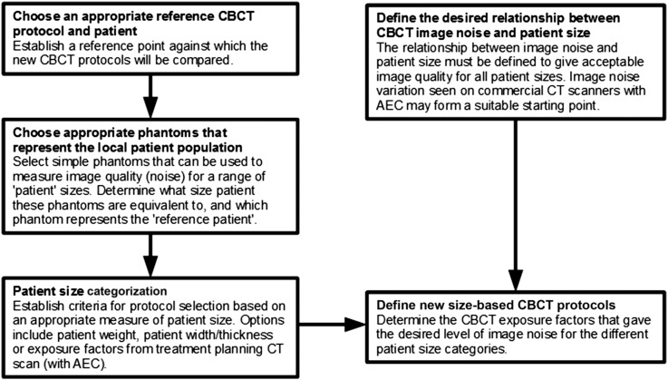
A flow chart is presented in Figure 2 that summarizes the general process that was followed to develop size-specific pelvis CBCT exposure protocols for the Varian OBI system. The starting point for this work was the manufacturer's default exposure factors and the locally derived “small patient” protocol (Table 1), with the latter taken as the reference CBCT protocol to which the new size-based exposure factors would be compared. For the purposes of this study, the small patient discussed in the introduction was used as the reference patient, but alternative configurations could be utilized where appropriate, e.g. a large patient with the manufacturer's default exposure protocol. Phantoms of varying size that represent the local patient population were then selected, and the equivalent patient size that each phantom represents was determined. In this study, the CT AEC phantom (Leeds Test Objects, Boroughbridge, UK) was used, which also includes a section that is equivalent to the small patient detailed above. A patient size categorization strategy was then developed based on size distribution from a sample of 100 patients. Patients were separated into small, medium, large or extra-large based on the exposure factors selected by the CT AEC system used during the treatment planning CT scan. New CBCT exposure factors were then derived which gave a gradual increase in image noise as patient size increases, in a way that matched the Philips Brilliance CT Big Bore 16-slice scanner (Philips Medical Systems, Best, Netherlands). Alternative relationships for how image noise varies with patient size could be selected based on local requirements. The following sections describe the detailed process that was implemented in this study to derive new protocols for pelvic CBCT.
Figure 2.
A flow chart of the process used to develop size-based cone beam CT (CBCT) protocols. AEC, automatic exposure control.
Table 1.
Manufacturer's default protocol settings for pelvis examinations on the Varian On-Board-Imager CBCT system (Varian® Medical Systems, Palo Alto, CA) and the locally derived small pelvis protocol
| Parameter | Varian default | Small pelvis |
|---|---|---|
| Software version | 1.5 | 1.5 |
| Source-to-isocentre distance (cm) | 100 | 100 |
| Source-to-detector distance (cm) | 150 | 150 |
| Bowtie filter | Half-fan | Half-fan |
| Field of view (cm) | 45 | 45 |
| Scan length (cm) | 16 | 16 |
| Accelerating potential (kV) | 125 | 110 |
| Tube current (mA) | 80 | 40 |
| Pulse width (ms) | 13 | 13 |
| Number of projections | 655 | 655 |
| Pixel matrix | 384 × 384 | 384 × 384 |
| Slice thickness (mm) | 2.5 | 2.5 |
| Reconstruction filter | Sharp | Sharp |
| Ring suppression | Medium | Medium |
Image quality evaluation
Quantitative image quality measurements were performed on two OBI CBCT systems and one Philips Brilliance CT Big Bore 16-slice scanner with the Leeds Test Objects CT AEC phantom (Figure 3). The phantom was positioned at the isocentre for all scans. Owing to the limited scan length on the CBCT system, only the six largest sections were acquired in a single rotation, as this was found to be representative of a range of typical pelvis sizes (note, hereafter Section 1 refers to the largest part of the phantom, whereas Section 6 is the smallest). A range of CBCT exposures were used to scan the phantom with tube potentials of 110 and 125 kV, tube currents between 10 and 80 mA and pulse widths between 13 and 26 ms.
Figure 3.
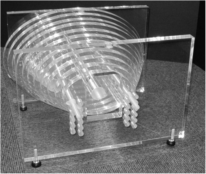
The Leeds Test Objects (Boroughbridge, UK) CT automatic exposure control phantom is composed of a series of 2.5-cm thick elliptical polymethyl methacrylate sections, with widths that range from 17.5 to 42.9 cm (with an aspect ratio of 3 : 2).
Measurements of CT number and standard deviation (hereafter referred to as “noise”) were performed for each set of exposure parameters evaluated in this study with a large central region of interest (excluding the central and supporting rods) using ImageJ v. 1.4732 (US National Institute of Health, Bethsheda, MD) (Figure 4). Image noise was characterized in Sections 2–6 of the phantom, as significant artefacts were present in the largest section. The mean standard deviation from the central six image slices within each section of the phantom was calculated and plotted as a function of phantom width. A linear fit was applied to the data, which was extrapolated to larger phantom sizes since the CT AEC phantom was not wide enough to mimic a pelvis scan of an “extra-large” patient.
Figure 4.
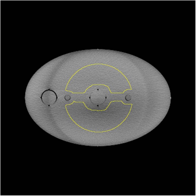
A single image slice of the CT automatic exposure control phantom with the large region of interest (ROI) is shown. The circular ROI was adapted to avoid the non-uniformities due to the central and supporting rods that run along the length of the phantom.
To determine “optimum” tube potential for average-size patients, image noise measurements for CBCT scans performed with 110 kV/80 mA/20 ms and 125 kV/80 mA/13 ms were compared. These exposure factors were used as they yield very similar patient effective and organ doses for an average-size patient [as determined with PCXMC 2.0 (STUK, Helsinki, Finland)33 and the technique described by Wood et al12].
Image noise was also assessed on the Philips Big Bore CT scanner for the “pelvis planning” protocol (Table 2). The DoseRight 2.0 AEC system that is used on this scanner determines the maximum tube current–time product per slice (mAs/slice) required to achieve acceptable image quality based on the most attenuating region within the scan volume, which in the case of pelvis CT scans tends to be around the region of the femoral heads.31 The longitudinal tube current modulator, Z-DOM, then reduces tube current relative to this value for regions that are less attenuating.
Table 2.
“Pelvis planning” CT protocol settings for the Philips Big Bore 16-slice CT scanner (Philips Medical Systems, Best, Netherlands)
| Parameter | Pelvis planning |
|---|---|
| AEC system | DoseRight 2.0 (ACS + Z-DOM) |
| Field of view (cm) | 50 |
| Accelerating potential (kV) | 120 |
| Reference mAs/slice | 170 |
| ACS water diameter (cm) | 34.1 |
| Rotation time (s) | 0.75 |
| Pitch | 0.813 |
| Beam collimation (mm) | 16 × 1.5 |
| Pixel matrix | 512 × 512 |
| Slice thickness (mm) | 3.0 |
| Reconstruction filter | Standard (B) |
ACS, automatic current selection; AEC, automatic exposure control; Z-DOM, Z-axis dose modulation.
Defining the reference cone beam CT protocol and patient
The starting point for this work was the locally derived “small pelvis” CBCT exposure protocol given in Table 1, which would be used for all patients who are the same size or smaller than the patient shown in Figure 1. To assess the size of individual patients compared with this reference, the exposure factors selected by the DoseRight 2.0 CT AEC system during the pre-treatment planning CT scan were used to infer the relative size of different patients. For the patient shown in Figure 1, the planning CT scan used a maximum of 155 mAs/slice when scanning through the femoral head region of the pelvis. From scanning the CT AEC phantom with the same protocol, it was established that Section 4 of the phantom (36.8 cm wide) gave the same exposure factors, which meant the overall attenuation properties were similar to the small patient (though clearly the structure within them are quite different). For this reason, Section 4 of the CT AEC phantom was taken to be the “small patient reference point”, to which all other protocols would be compared.
Defining the relationship between cone beam CT image noise and patient size
The DoseRight 2.0 system on the Philips Big Bore CT scanner aims to maintain “acceptable image noise”, which means that whilst noise increases with patient size, image quality should remain sufficient for the clinical task. This tends to limit the increase in dose that would be required for obese patients if the system used the alternative constant noise technique found on systems from other manufacturers.30 This acceptable noise technique was used as the basis for defining the size-based CBCT protocols in this study. To define this relationship between noise and patient size (the “CT noise reference”), the noise measured in each section of the CT AEC phantom on the Philips CT scanner was normalized relative to that measured in Section 4 (the small patient reference point). This indicated the fractional increase in noise that would be required from the CBCT scans for any given phantom width, when compared with the noise measured at the small reference point.
Patient size categorization
The small patient reference point (155 mAs/slice for Section 4 of the CT AEC phantom) was taken to define the upper limit for the “small” CBCT protocol, but for the purposes of patient size determination, this was rounded up to 160 mAs/slice, i.e. any patient whose planning CT scan gave a maximum exposure factor ≤160 mAs/slice would use the small CBCT protocol. The boundaries between the other protocols were determined from a routine patient dose audit of 100 pelvis planning CT scans and the resulting distribution of exposure factors. The boundary between the medium and large protocols was taken to be the median of this sample (rounded up to the nearest 10 mAs/slice), whereas the boundary between the large and extra-large protocols was determined by the maximum mAs/slice possible on the default pelvis planning protocol.
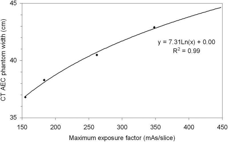
The mAs/slice at the boundary between each protocol was then converted to a corresponding phantom width to define the physical phantom size range for each of the four CBCT protocols. From the scan of the AEC phantom on the CT scanner, phantom width was plotted as a function of mAs/slice used to image each section. A logarithmic function was fitted to the data, and the phantom width corresponding to the mAs/slice at the border between each protocol was calculated.
Defining new size-based exposure protocols
Image noise was plotted as a function of phantom width for the small pelvis CBCT protocol (110 kVp, 40 mA and 13 ms), and the CT noise reference was scaled to match the noise at the small patient reference point. The phantom widths that correspond to the boundaries between the medium–large and large–extra-large protocols were indicated on this plot, and CBCT exposure factors that gave noise levels that matched the CT noise reference at these points were determined empirically. These exposure factors were taken to form the sized-based CBCT protocols. The CT noise reference was taken as a limit that should not be exceeded by any size-based CBCT protocol over the range of phantom sizes that applied to that protocol.
Patient dose evaluation for the new cone beam CT protocols
Patient dose for average-size patients was assessed by estimating organ and effective doses for the medium protocol and the Varian default settings using PCXMC 2.0 (STUK)33 and the technique described by Wood et al.12 This method uses a simple mathematical phantom and a series of narrow radiation beams that mimic the effect of the half-fan bowtie filter. The field co-ordinates, total tube filtration and patient height used by Wood et al12 were used for this study, whereas a radiation output profile across the bowtie filter for 110 and 125 kVp was derived with a calibrated Unfors Xi R/F detector (Unfors-Raysafe, Billdal, Sweden). From this profile, the air kerma at the reference point was calculated for the exposure factors used in the two CBCT protocols.
RESULTS
Image quality evaluation
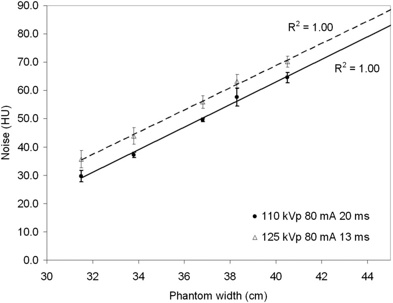
Figure 5 shows a plot of noise (standard deviation of CT numbers) against phantom width for 110 kVp, 80 mA and 20 ms, compared with 125 kVp, 80 mA and 13 ms. These exposure factors give similar organ and effective doses (on average within 6%), but image noise is typically 13% lower for 110 kVp for any given phantom width. This will be due to the reduced scatter and improved detector efficiency at lower tube potentials and is the reason that 110 kVp has been used for the small to large patient CBCT protocols.
Figure 5.
Image noise as a function of phantom width for two sets of exposure factors on the cone beam CT systems (110 kVp, 80 mA and 20 ms) and the default pelvis exposure factors (125 kVp, 80 mA and 13 ms). A linear fit has been applied to the data with R2 = 1.00 in both cases.
Defining the relationship between cone beam CT image noise and patient size
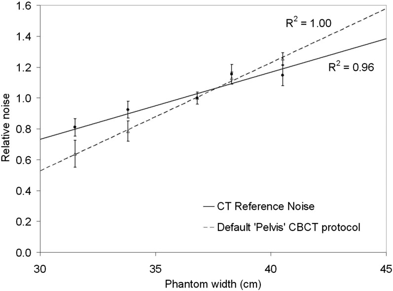
A plot of relative noise variation with phantom width for the pelvis planning protocol on the Philips CT scanner is shown in Figure 6 along with the Varian default pelvis CBCT protocol. The data for the Philips CT scanner formed the “CT noise reference” that was used to find appropriate CBCT exposure factors for small, medium, large and extra-large patients. It can be seen that image noise increases more gradually with the CT AEC system as it is able to increase exposure factors for larger phantom widths (and vice versa), unlike the manufacturer's default CBCT protocol which uses the same exposure factors for all patient sizes.
Figure 6.
Relative noise variation with phantom width for the “pelvis planning” CT protocol on the Brilliance Big Bore system (with DoseRight 2.0 CT and Z-DOM), and the default “pelvis” CBCT protocol on the Varian On-Board-Imager system (Varian® Medical Systems, Palo Alto, CA). Both plots are normalized relative to the “small patient” size.
Patient size categorization
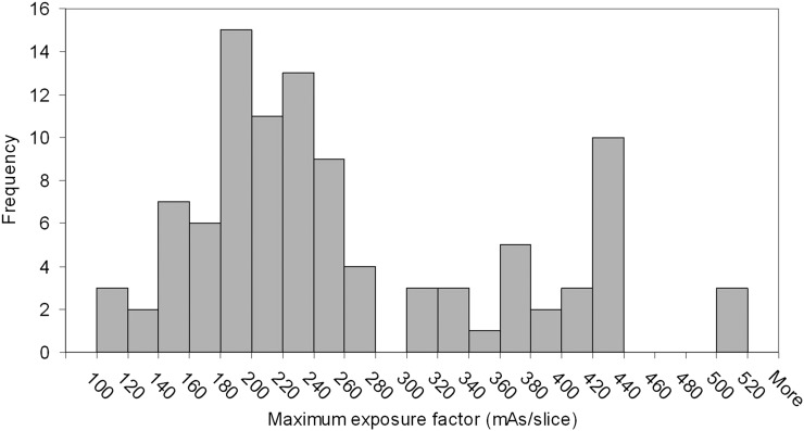
Figure 7 shows a histogram of the maximum mAs/slice used by the Philips CT AEC system on a sample of 100 pelvis planning CT scans. The boundary between small and medium CBCT protocols has already been defined as 160 mAs/slice based on the previous clinical optimization work. This accounts for 12% of this patient sample, with average weight of 60 kg. The rounded median of this sample was 240 mAs/slice, which was taken to be the limit for the medium CBCT protocol (45% of this sample with average weight of 78 kg). For the border between the large and extra-large protocols, the distribution demonstrates a peak corresponding to 420–440 mAs/slice that is due to the CT scanner reaching its maximum X-ray tube current limit. To increase exposure factors further, the operator has to increase tube rotation time; the distribution shows that this does not always happen as only 3% of the sample had exposure factors greater than this limit, whereas 10% were scanned using the maximum mAs/slice for the default pelvis planning protocol. For this reason, the border between the large and extra-large patients was taken to be 420 mAs/slice, as beyond this value, it cannot be certain that exposure factors are an accurate representation of patient size. This results in 13% of the sample being classified as extra-large (with average weight of 111 kg), and 30% falling in the large category (average weight of 94 kg). These exposure factors were used to generate the CBCT protocol lookup table given in Table 3. The operator who performs the CBCT scan uses the maximum mAs/slice from the planning CT scan that is recorded on the radiotherapy record and verify system (Aria® 11; Varian Medical Systems) to decide which CBCT protocol is appropriate. As these data already exist as part of the patient record, no additional data capture was required.
Figure 7.
Histogram of patient exposure factors for a sample of 100 pelvis planning CT scans.
Table 3.
The cone beam CT (CBCT) protocol lookup table for determining patient size
| CBCT pelvic protocol | Maximum mAs/slice for “pelvis” CT planning protocol (using DoseRight 2.0 CT AEC) |
|
|---|---|---|
| From (mAs/slice) | To (mAs/slice) | |
| Small | – | 160 |
| Medium | 161 | 240 |
| Large | 241 | 420 |
| Extra-large | 421 | – |
AEC, automatic exposure control; mAs, tube current–exposure time.
These values only apply to the specific CT and CBCT systems in this study.
To convert these mAs/slice values into equivalent phantom size ranges, phantom width was plotted as a function of mAs/slice for the Philips CT scanner as shown in Figure 8. A logarithmic function was fitted to the data (R2 = 0.99), and the range of phantom widths that corresponds to each CBCT protocol were determined. The limits on phantom width for the small, medium and large protocols were 37.1, 40.1 and 44.2 cm, respectively (note, extra-large was taken to be anything >44.2 cm).
Figure 8.
CT automatic exposure control phantom width as a function of tube–current time product per slice for the local pelvis planning CT protocol. A logarithmic fit to the data is shown (R2 = 0.99).
Defining size-based cone beam CT exposure protocols
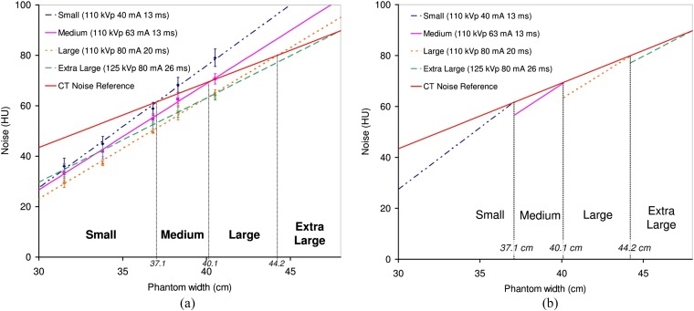
Figure 9a shows a plot of noise as a function of phantom width for the small CBCT protocol (110 kVp, 40 mA and 13 ms) and the CT noise reference scaled to match the absolute noise level at the small patient reference point. The exposure factors that were empirically found to cross the CT noise reference at 40.1 and 44.2 cm were determined and are also shown in Figure 9a. These correspond to the medium (110 kVp, 63 mA and 13 ms) and large (110 kVp, 80 mA and 20 ms) CBCT protocols. The extra-large protocol uses 125 kVp, 80 mA and 26 ms owing to the limitations on the X-ray tube exposure factors at 110 kVp and to ensure the beam was sufficiently penetrating to pass through extra-large patients. The pulse width was doubled compared with the Varian default pelvis protocol to ensure image quality was sufficient on patients of this size. Figure 9b shows a simplified plot with the noise variation for each protocol only shown for the range of phantom sizes that each one should be used for. It can be seen that this approach to size-based CBCT protocols means that overall image noise is better matched to the desired CT noise reference, when compared with the rapid increase in noise observed with a single set of fixed exposure factors (Figure 6).
Figure 9.
(a) Absolute noise variation as a function of phantom width for a range of cone beam CT exposure factors that were found to be appropriate for small, medium, large and extra-large patients, compared with the CT reference noise (scaled to match the small protocol at 37.1-cm phantom width). Linear fits have been applied to the data and extrapolated to larger phantom sizes (R2 = 1.00 for all four protocols). (b) The same data, but only showing noise variation over the range of phantom sizes that each protocol is applicable to.
Patient dose evaluation
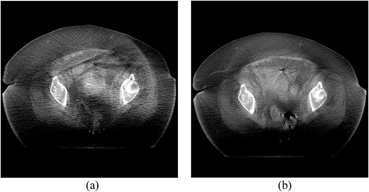
Effective dose and selected organ dose estimates for the medium protocol compared with the Varian default settings are given in Table 4. These figures are for a single CBCT scan and should be multiplied by the total number of scans to determine the additional dose burden from concomitant exposures. Radiation doses are significantly lower than the Varian default settings without compromising clinical image quality (an approximate 45% saving). The small protocol will yield even greater dose savings owing to the lower mA setting that is used, whereas “large patients” will receive a similar radiation dose to the Varian settings as the large protocol uses double the mAs of the medium protocol. For extra-large patients, radiation dose will be doubled compared with the Varian default settings, but this is justified by the improvement in image quality which now enables operators to see the soft-tissue detail in these types of patient (as demonstrated in Figure 10).
Table 4.
Effective dose and selected mean organ dose estimates for the medium pelvis cone beam CT (CBCT) protocol applied to prostate treatments, compared with the original Varian default settings
| Protocol | Varian | Medium |
|---|---|---|
| Effective dose (mSv) | 6.0 ± 0.1 | 3.3 ± 0.1 |
| Mean colon dose (mGy) | 7.5 ± 0.1 | 4.0 ± 0.1 |
| Mean testicles dose (mGy) | 37.7 ± 0.5 | 21.3 ± 0.3 |
| Mean bladder dose (mGy) | 29.9 ± 0.4 | 16.3 ± 0.2 |
| Mean prostate dose (mGy) | 28.6 ± 0.7 | 15.4 ± 0.4 |
All doses were estimated using PCXMC 2.0 (STUK, Helsinki, Finland) and the technique described by Wood et al.12
Figure 10.
Cone beam CT (CBCT) images of (a) an obese patient scanned with the manufacturer's default pelvis protocol (125 kVp, 80 mA and 13 ms) and (b) the same patient scanned with the extra-large protocol (125 kVp, 80 mA and 26 ms).
DISCUSSION
Optimization of CBCT imaging protocols is an area of significant interest in the literature. However, most previous studies12–24 have been primarily concerned with the quantification of imaging dose through a range of different techniques to understand the risk associated with the use of this technology in the context of modern radiotherapy treatments. Whilst some studies have considered strategies for reducing patient exposure during CBCT examinations, this study has focused on one of the most significant parameters that affects both patient dose and the resulting image quality, i.e. patient size.
This study has developed a strategy that has built on previous clinical experience of patient dose optimization to create a series of size-based pelvis CBCT protocols for patients who may be classified as small, medium, large or extra-large. For the majority of patients in our centre (57%), these protocols result in much lower radiation dose, with the smallest patients receiving doses that are approximately one-third of those given by the manufacturer's default exposure protocol. Despite this significant reduction in exposure, image quality remains acceptable for the clinical task.
For the 30% of patients who are classified as “large”, the new CBCT protocol will be relatively dose neutral, but the image quality assessment has shown that by reducing tube kilovoltage to 110 kVp, image noise is lower owing to the reduction in scattered radiation and the increased efficiency of the caesium iodide-based flat panel detector. This highlights the importance of understanding that the response of these types of CBCT system are more similar to flat panel digital radiography systems than conventional CT scanners when it comes to optimization, as they both share the same technology and limitations, e.g. flat panel detectors and antiscatter grids.
Finally, for the remaining 13% of patients who are classified as extra-large, it has been demonstrated that increased exposure factors are justified as the reduction in image noise improves clinical image quality to the extent that it is possible to see soft-tissue detail that would otherwise be obscured when using the default exposure protocol. The limitations of the X-ray tube used on the OBI system and the requirement for good penetration through these extra-large patients mean that a higher tube potential of 125 kVp is required, despite the increase in scatter that will have a negative impact on image quality.
Whilst the benefits of these size-specific protocols are clear, it has been essential to develop a robust technique for choosing the correct protocol for each individual patient, rather than relying on the operator to select the appropriate one based on a subjective assessment of patient size. One simple technique would have been to use patient weight as selection criteria for defining whether they are small, medium, large or extra-large. However, weight can be misleading as it does not take into account the distribution of mass around the body (particularly in a bony area such as the pelvis), and the resulting attenuation properties that are so important in deciding appropriate exposure factors for any given patient. For this reason, the information already available from the CT planning scan has been utilized to create simple selection criteria based on the maximum exposure factor used on the patient. The pre-treatment Philips Brilliance Big Bore CT scanner which was the subject of this study uses the DoseRight 2.0 AEC system to determine appropriate exposure factors for individual patients based on the variations in size observed in the scanning projection radiograph. The maximum tube current is typically found in the region around the femoral heads, which also tends to be the area that is of clinical interest in the CBCT scan when the patient is on the treatment machine. By looking at the typical distribution of patient exposure factors at the Queen's Centre for Oncology and Haematology, it has been possible to derive a simple lookup table that defines which CBCT protocol should be used based on the CT exposure factors that are recorded in the radiotherapy record and verify system. It is important to note, however, that unlike many other aspects of the radiotherapy treatment, this should not be treated like a prescription, but rather a guide to appropriate settings; further optimization based on the quality of the acquired images may be necessary (e.g. change from a small to medium protocol or vice versa), but this has not been required in the 6 months that these protocols have been in clinical use on three linear accelerators at the Queen's Centre for Oncology and Haematology.
One potential limitation of this approach is that the lookup table developed in this study is specific to the CT scanners and protocols that are currently implemented for “pelvis planning” scans in our Trust. If scan protocols are altered (e.g. as part of an optimization exercise) or if the scanner is replaced with a new model, a new lookup table will need to be derived. However, the approach outlined in this study could be repeated to redefine the relevant boundaries between different patient sizes. Alternative approaches for defining patient size could also be used, such as measuring patient size directly on the CT image slices, but this requires additional steps at the scanner console and is prone to errors as it will be dependent on the slice that is chosen for measuring patient size; this would require standardization and can be difficult to define, e.g. maximum patient width, thickness or standard anatomical landmark. Also, patients' external dimensions do not always correspond with the attenuation properties in the region that is of clinical interest for CBCT scans.
Whilst the system described in this study is currently in clinical use with no reported issues, there are some limitations to the current work that would be of interest for future development. The lack of availability of phantoms with sufficient size to mimic an extra-large pelvis has meant that noise has been estimated for these size ranges based on the extrapolation of the measurements made in the CT AEC phantom. However, this is not anticipated to be a significant problem given that the linear fit to data from this slightly smaller phantom was excellent (R2 = 1.00 for all CBCT protocols). Another factor that may be considered is the use of such simple uniform phantoms for the derivation of these size-based protocols. The lack of any real anatomical detail or structure in the CT AEC phantom may limit the scope for optimization with this particular test object, but the results of this study and subsequent application in clinical practice have shown that it is possible to derive acceptable protocols for patients of different sizes, which are a significant improvement on the fixed default exposure factors for all sizes. Additional work may be able to refine these protocols further with more advanced anthropomorphic phantoms. It should also be stressed that whilst the present study used the Leeds Test Objects CT AEC phantom, alternative phantoms may also be used to derive exposure protocols using the general principles outlined in this study, provided they cover an appropriate range of patient sizes. Finally, the optimization of CBCT protocols has only considered optimization of exposure factors whilst using the manufacturer's default reconstruction parameters. Further optimization of image quality may be possible with different reconstruction filters, image slice thickness, matrix size and number of projections.
One final point worth noting is that whilst the approach taken in this study used an “optimized” small pelvis CBCT protocol as the reference to which all others were compared, alternative strategies and starting points may be used. For example, in some centres, it may be appropriate to start with the manufacturer's default protocol on average-size patients as the base from which the size-based protocols could be defined (through an appropriate relationship between image noise and phantom size). An extra final optimization step could then be included in the process whereby all size-based protocols are optimized to ensure patient doses are as low as reasonably achievable.
CONCLUSION
A relatively simple strategy for the implementation of size-based CBCT protocols has been developed for the Varian OBI system, which means that patient radiation dose is kept as low as reasonably achievable whilst ensuring that image quality remains acceptable for the clinical task at hand. For the majority of patients at the Queen's Centre for Oncology and Haematology, it has been demonstrated that significant dose reductions are possible without compromising the clinical acceptability of the resulting images, when compared with the default exposure factors provided by the manufacturer of this system. To make the most of these new exposure protocols, a robust technique for selecting the appropriate protocol for each individual patient has been developed, which is based on the exposure factors chosen by the CT AEC during the original radiotherapy treatment planning scan. A simple lookup table linking the maximum mAs/slice (i.e. the size of the most attenuating part of the patient) to the appropriate CBCT protocol has been developed for the specific systems used in this hospital.
Contributor Information
Tim J Wood, Email: tim.wood@hey.nhs.uk.
Craig S Moore, Email: craig.moore@hey.nhs.uk.
Carl J Horsfield, Email: carl.horsfield@hey.nhs.uk.
John R Saunderson, Email: john.saunderson@hey.nhs.uk.
Andrew W Beavis, Email: andy.beavis@hey.nhs.uk.
REFERENCES
- 1.De Los Santos J, Popple R, Agazaryan N, Bayouth JE, Bissonnette J-P, Bucci MK, et al. Image guided radiation therapy (IGRT) technologies for radiation therapy localization and delivery. Int J Radiat Oncol Biol Phys 2013; 87: 33–45. doi: 10.1016/j.ijrobp.2013.02.021 [DOI] [PubMed] [Google Scholar]
- 2.Murphy MJ, Balter J, Balter S, BenComo JA, Das IJ, Jiang SB, et al. The management of imaging dose during image-guided radiotherapy: report of the AAPM Task Group 75. Med Phys 2007; 34: 4041–63. doi: 10.1118/1.2775667 [DOI] [PubMed] [Google Scholar]
- 3.Dawson LA, Sharpe MB. Image-guided radiotherapy: rationale, benefits, and limitations. Lancet Oncol 2006; 7: 848–58. doi: 10.1016/S1470-2045(06)70904-4 [DOI] [PubMed] [Google Scholar]
- 4.van Herk M. Different styles of image-guided radiotherapy. Semin Radiat Oncol 2007; 17: 258–67. doi: 10.1016/j.semradonc.2007.07.003 [DOI] [PubMed] [Google Scholar]
- 5.Verellen D, De Ridder M, Storme G. A (short) history of image-guided radiotherapy. Radiother Oncol 2008; 86: 4–13. doi: 10.1016/j.radonc.2007.11.023 [DOI] [PubMed] [Google Scholar]
- 6.Beavis A. Image-guided radiation therapy: what is our Utopia? Br J Radiol 2010; 83: 191–3. doi: 10.1259/bjr/26132255 [DOI] [PMC free article] [PubMed] [Google Scholar]
- 7.McBain CA, Henry AM, Sykes J, Amer A, Marchant T, Moore CM, et al. X-ray volumetric imaging in image-guided radiotherapy: the new standard in on-treatment imaging. Int J Radiat Oncol Biol Phys 2006; 64: 625–34. doi: 10.1016/j.ijrobp.2005.09.018 [DOI] [PubMed] [Google Scholar]
- 8.Yan D, Vicini F, Wong J, Martinez A. Adaptive radiation therapy. Phys Med Biol 1997; 42: 123–32. doi: 10.1088/0031-9155/42/1/008 [DOI] [PubMed] [Google Scholar]
- 9.Burridge N, Amer A, Marchant T, Sykes J, Stratford J, Henry A, et al. Online adaptive radiotherapy of the bladder: small bowel irradiated-volume reduction. Int J Radiat Oncol Biol Phys 2006; 66: 892–97. doi: 10.1016/j.ijrobp.2006.07.013 [DOI] [PubMed] [Google Scholar]
- 10.Richter A,Hu Q, Steglich D, Baier K, Wilbert J, Guckenberger M, et al. Investigation of the usability of cone beam CT data sets for dose calculation. Radiat Oncol 2008; 3: 42. doi: 10.1186/1748-717X-3-42 [DOI] [PMC free article] [PubMed] [Google Scholar]
- 11.Elstrøm UV, Wysocka BA, Muren LP, Petersen JPP, Grau C. Daily kV cone-beam CT and deformable image registration as a method for studying dosimetric consequences of anatomic changes in adaptive IMRT of head and neck cancer. Acta Oncol 2010; 49: 1101–8. [DOI] [PubMed] [Google Scholar]
- 12.Wood TJ, Moore CS, Saunderson JR, Beavis AW. Validation of a technique for estimating organ doses for kilovoltage cone-beam CT of the prostate using the PCXMC 2.0 patient dose calculator. J Radiol Prot 2015; 35: 153–63. doi: 10.1088/0952-4746/35/1/153 [DOI] [PubMed] [Google Scholar]
- 13.Sykes JR, Lindsay R, Iball G, Thwaites DI. Dosimetry of CBCT: methods, doses and clinical consequences. J Phys Conf Ser 2013; 444: 012017. [Google Scholar]
- 14.Shah A, Aird E, Shekhdar J. Contribution to normal tissue dose from concomitant radiation for two common kV-CBCT systems and one MVCT system used in radiotherapy. Radiother Oncol 2012; 105: 139–44. doi: 10.1016/j.radonc.2012.04.017 [DOI] [PubMed] [Google Scholar]
- 15.Stock M, Palm A, Altendorfer A, Steiner E, Georg D. IGRT induced dose burden for a variety of imaging protocols at two different anatomical sites. Radiother Oncol 2012; 102: 355–63. doi: 10.1016/j.radonc.2011.10.005 [DOI] [PubMed] [Google Scholar]
- 16.Hyer DE, Serago CF, Kim S, Li JG, Hintenlang DE. An organ and effective dose study of XVI and OBI cone-beam CT systems. J Appl Clin Med Phys 2010; 11: 181–97. [DOI] [PMC free article] [PubMed] [Google Scholar]
- 17.Hyer DE, Hintenlang DE. Estimation of organ doses from kilovoltage cone-beam CT imaging used during radiotherapy patient position verification. Med Phys 2010; 37: 4620–6. doi: 10.1118/1.3476459 [DOI] [PubMed] [Google Scholar]
- 18.Sawyer LJ, Whittle SA, Matthews ES, Starritt HC, Jupp TP. Estimation of organ and effective doses resulting from cone beam CT imaging for radiotherapy treatment planning. Br J Radiol 2009; 82: 577–84. doi: 10.1259/bjr/62467578 [DOI] [PubMed] [Google Scholar]
- 19.Gu J, Bednarz B, Xu XG, Jiang SB. Assessment of patient organ doses and effective doses using the VIP-man adult male phantom for selected cone-beam CT imaging procedures during image guided radiation therapy. Radiat Prot Dosim 2008; 131: 431–43. doi: 10.1093/rpd/ncn200 [DOI] [PubMed] [Google Scholar]
- 20.Spezi E, Downes P, Jarvis R, Radu E, Staffurth J. Patient-specific three-dimensional concomitant dose from cone beam computed tomography exposure in image-guided radiotherapy. Int J Radiat Oncol Biol Phys 2012; 83: 419–26. doi: 10.1016/j.ijrobp.2011.06.1972 [DOI] [PubMed] [Google Scholar]
- 21.Alaei P, Ding G, Guan H. Inclusion of the dose from kilovoltage cone beam CT in the radiation therapy treatment plans. Med Phys 2010; 37: 244–8. doi: 10.1118/1.3271582 [DOI] [PubMed] [Google Scholar]
- 22.Ding GX, Munro P. Radiation exposure to patients from image guidance procedures and techniques to reduce the imaging dose. Radiother Oncol 2013; 108: 91–8. doi: 10.1016/j.radonc.2013.05.034 [DOI] [PubMed] [Google Scholar]
- 23.Ding GX, Munro P, Pawlowski J, Malcolm A, Coffey CW. Reducing radiation exposure to patients from kV-CBCT imaging. Radiother Oncol 2010; 97: 585–92. doi: 10.1016/j.radonc.2010.08.005 [DOI] [PubMed] [Google Scholar]
- 24.Roxby P, Kron T, Foroudi F, Haworth A, Fox C, Mullen A, et al. Simple methods to reduce patient dose in a Varian cone beam CT system for delivery verification in pelvic radiotherapy. Br J Radiol 2009; 82: 855–9. doi: 10.1259/bjr/37579222 [DOI] [PubMed] [Google Scholar]
- 25.Wang J, Li T, Liang Z, Xing L. Dose reduction for kilovoltage cone-beam computed tomography in radiation therapy. Phys Med Biol 2008; 53: 2897–909. doi: 10.1088/0031-9155/53/11/009 [DOI] [PubMed] [Google Scholar]
- 26.International Commission on Radiological Protection. The 2007 Recommendations of the International Commission on Radiological Protection. ICRP Publication 103. Ann ICRP 2007; 37. [DOI] [PubMed] [Google Scholar]
- 27.The Ionising Radiation (Medical Exposure) Regulations (IR(ME)R) 2000 (SI 2000 No. 1059). London, UK: The Stationary Office; 2000. [Google Scholar]
- 28.International Commission on Radiological Protection. Managing patient dose in computed tomography, ICRP Publication 87. Ann ICRP 2000; 30. [DOI] [PubMed] [Google Scholar]
- 29.Keat N. CT scanner automatic exposure control systems, MHRA Evaluation Report 05016. London, UK: HMSO; 2005. [Google Scholar]
- 30.Sookpeng S, Martin CJ, Gentle DJ, Lopez-Gonzalez MR. Relationships between patient size, dose and image noise under automatic tube current modulation systems. J Radiol Prot 2014; 34: 103–23. doi: 10.1088/0952-4746/34/1/103 [DOI] [PubMed] [Google Scholar]
- 31.Wood TJ, Moore CS, Stephens A, Saunderson JR, Beavis AW. A practical method to standardise and optimise the Philips DoseRight 2.0 CT automatic exposure control system. J Radiol Prot 2015; 35: 495–506. doi: 10.1088/0952-4746/35/3/495 [DOI] [PubMed] [Google Scholar]
- 32.Rasband WS. ImageJ, 1997–2014. Bethesda, MD. U. S. National Institutes of Health. Available from: http://imagej.nih.gov/ij/ [Google Scholar]
- 33.Tapiovaara M, Lakkisto M, Servomaa A. PCXMC: A PC-based Monte Carlo program for calculating patient doses in medical x-ray examinations Report STUK-A139. Helsinki, Finland: Finnish Centre for Radiation and Nuclear Safety; 1997. [Google Scholar]


