

Abstract
Spin-echo-based pulse sequences are desirable for the application of high-resolution imaging of trabecular bone but tend to involve high-power deposition. Increased availability of ultrahigh field scanners has opened new possibilities for imaging with increased signal-to-noise ratio (SNR) efficiency, but many pulse sequences that are standard at 1.5 and 3 T exceed specific absorption rate limits at 7 T. A modified, reduced specific absorption rate, three-dimensional, fast spin-echo pulse sequence optimized specifically for in vivo trabecular bone imaging at 7 T is introduced. The sequence involves a slab-selective excitation pulse, low-power nonselective refocusing pulses, and phase cycling to cancel undesired out-of-slab signal. In vivo images of the distal tibia were acquired using the technique at 1.5, 3, and 7 T field strengths, and SNR was found to increase at least linearly using receive coils of identical geometry. Signal dependence on the choice of refocusing flip angles in the echo train was analyzed experimentally and theoretically by combining the signal from hundreds of coherence pathways, and it is shown that a significant specific absorption rate reduction can be achieved with negligible SNR loss.
Keywords: fast spin echo, FSE, RARE, trabecular bone, out-of-slab cancellation
Imaging of tissue microarchitecture is likely to benefit from the SNR enhancements brought about by rapid proliferation of high-field MRI technology. Whereas 3 T is now the accepted standard for achieving substantially improved performance in a wide range of imaging applications, the population of 7 T whole-body systems has been increasing rapidly (1) after initial results have demonstrated that unprecedented anatomic detail can be obtained. While initial work has focused on the brain (2), ultrahigh field may have particular potential for the study of microstructure and function of the peripheral musculoskeletal system (3,4). A case in point is the detailed analysis of bone structure, in particular the plate-rod characterization of trabecular bone as a means to gain insight into age- and disease-related structural alterations that can be studied serially to assess treatment efficacy (5).
Among the techniques in use for trabecular bone imaging, gradient-echo-based methods, notably steady-state free-precession with or without gradient moment balancing (6), are advantageous since they allow for short pulse repetition times, leading to practical scan times on the order of 10 min or less. Both embodiments, however, are prone to artifacts from induced inhomogeneous amplitude of static fields (7), a problem that is substantially exacerbated at elevated field strengths (3). For this reason, spin-echo methods have proven to be preferable for structural bone imaging owing to their relative insensitivity to magnetic field inhomogeneity. The three-dimensional (3D) fast large-angle spin-echo (FLASE) approach, of which a number of variants have been reported (8–11), enables efficient high-resolution imaging by reconciling the requirement for pulse repetition time ≫ T1.
However, power deposition constraints at 7 T limit the use of 3D FLASE, which involves two high flip-angle pulses per pulse sequence repetition period and a relatively short repetition time on the order of 80 ms. Specific absorption rate (SAR) scales with the square of field strength, and therefore roughly 20 times more power is deposited at 7 T relative to 1.5 T for the same pulse sequence. In the authors’ laboratory, this restriction has prevented the use of 3D FLASE on humans at 7 T, prompting us to develop an alternative, spin-echo technique based on a variable-flip-angle implementation of 3D rapid acquisition with relaxation enhancement (RARE) (12–14).
The new variant of the variable-refocusing flip angle sequence here is termed 3D fast spin-echo with out-of-slab cancellation (3D FSE-OSC). Even though a slab of limited width is excited, the sequence makes use of nonselective refocusing pulses (unlike conventional FSE), and phase cycling is applied to cancel signal generated from magnetization outside the imaging slab, as well as in-slab signal originating from the refocusing pulses. Nonselective pulses are key in this application because they can be made short and have significantly less power than selective refocusing pulses of similar duration.
One of the hallmarks of FSE is increased intensity from fatty acid triglycerides (the major constituents of yellow marrow) (15), resulting from refocusing of J-modulation dephasing (16). Therefore, FSE-based pulse sequences should benefit from SNR increase for the target applications: high-resolution imaging of trabecular bone in the distal extremities such as the distal radius and tibia (17).
Aside from depositing less power, another significant advantage of 3D FSE-OSC is its higher readout bandwidth (108 Hz/pixel as compared with 32 Hz/pixel for FLASE in the authors’ implementations). This is particularly important at high and ultrahigh field where the spectrum of fat is broadened. Thus, the proposed pulse sequence features an appreciably narrower point-spread function in the readout direction.
MATERIALS AND METHODS
Pulse Sequence
The 3D FSE-OSC pulse sequence is depicted in Fig. 1. The sequence differs from traditional 3D FSE sequences in several ways. As mentioned in the introduction, the primary difference is that whereas the (90°) excitation pulse selects a slab for 3D imaging, the refocusing radio-frequency (RF) pulses are nonselective. Normally, this would cause severe artifacts in the presence of even very slight amplitude of RF field inhomogeneity because of spurious magnetization excited outside the imaging slab. As is shown in the Results section, artifacts exist even when crusher gradients are used. To avoid this problem, every phase-encode line is acquired twice, with the phase of the excitation pulse alternating between 0 and 180 degrees. The phase of each refocusing pulse is held constant at 90° relative to the initial excitation pulse (Carr-Purcell-Meiboom-Gill condition, as in conventional FSE imaging (18)). Before reconstruction, the data are combined via subtraction of the two acquisitions, so that the desired magnetization (i.e., magnetization excited by the initial selective pulse) is combined constructively, whereas out-of-slab magnetization is exactly cancelled. Because the phase alternation is the innermost loop in the sequence, and since subtraction is performed before any other reconstruction steps, the cancellation is robust to slight patient motion or other variations throughout the scan. Of course, this phase alternation results in doubling of the minimum scan time. However, the signal-to-noise efficiency (i.e., SNR per unit time) does not suffer since the subtraction results in a constructive combination of the desired signal. Also, taking advantage of the symmetry of k-space, we collect only 60% of kY lines. With pulse repetition time = 500 ms, and eight echoes per repetition, scan time (before parallel imaging) was therefore 460 × 32 × (two phase cycles) × (500 ms)/(eight echoes) × 60% = 1104 sec, or around 18.4 min, for a 460 × 460 × 32 data array. With parallel imaging, scan time was reduced to 10.2 min (R = 1.8).
FIG. 1.
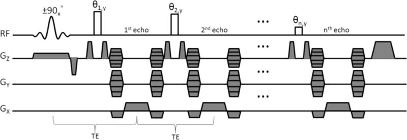
Pulse-sequence diagram for 3D FSE-OSC. It is noted that the gradient moment for Y-encoding is held constant for a given echo train (i.e., pulse repetition period), while the Z-encoding gradient is stepped to cover kz-space in a segmented fashion (see Fig. 2).
Phase encoding in the slab-select (Z) direction is segmented. Within each repetition, eight different kZ lines were acquired, with centric ordering (so that the center of kZ-space was acquired first). This scheme was repeated four times to cover a total of 32 kZ lines (see the resulting modulation transfer function of Fig. 2). Although not strictly necessary (considering out-of-slab cancellation), crusher gradients were applied on either side of the refocusing pulses to reduce the magnitude of the unwanted signal.
FIG. 2.
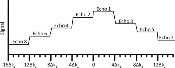
Depiction of modulation transfer function in the slice direction, before correction.
To reduce time-averaged SAR, variable flip angles were used for the refocusing pulses. As shown previously (14,19), it is generally desirable to use high flip angles for the first pulses in the echo train, with gradual decrease to lower flip angles toward the end of the train. In this manner, the later echoes benefit from the large number of coherences being constructively refocused, whereas the earlier echoes rely on larger flip angles to achieve high signal. In this work, we use a flip angle train of the form {180°, 180° − δ, 180° − 2δ, …, 180° − (n − 1) δ>, where n is the number of echoes in the train, and δ is the angle decrease from one pulse to the next. For example, δ = 12.86° and n = 8 leads to a sequence of angles decreasing linearly from 180° to 90°. While other sequences of flip angles may prove to be more SNR efficient, the Appendix contains calculations indicating that the use of linearly decreasing flip angles is desirable and perhaps optimal. See also the Discussion section for a comparison with pseudo-steady-state techniques and rationale for acquiring only eight echoes per repetition.
The interecho spacing is restricted by the readout time, the duration of the nonselective pulses, and the duration of the phase-encode gradients, which are fully rewound between each pair of refocusing pulses in order to satisfy the Carr-Purcell-Meiboom-Gill condition (the readout gradients are also rewound). A refocusing pulse duration of 1 ms and a maximum gradient amplitude of 20 mT/m were used to yield an echo spacing of echo time = 20 ms. Readout bandwidth was 108 Hz/pixel and pixel size 137 × 137 μm2, with 410-μm slice thickness for a readout time of 9.2 ms per echo. The field of view was 63 × 63 mm2.
In addition to this anisotropic imaging protocol, which matches the resolution and field of view of the authors’ standard 3D FLASE implementation, an isotropic version of 3D FSE-OSC was also developed. To achieve 160 μm isotropic resolution in a comparable scan time, the in-plane field of view was reduced from 63 × 63 to 60.8 × 60.8 mm2 and the slab thickness was reduced from 13.1 to 7.7mm. By increasing the number of Z-encode interleaves to six, 48 slices were acquired in a scan time of 13 min, again using parallel imaging with R = 1.8. The only other difference between the anisotropic and isotropic protocols was that the crusher gradients were applied in the Z and X directions, respectively, for the anisotropic and isotropic scans.
Echo Modulation Correction
As shown in Fig. 2, segmentation of the kZ phase encoding (along the slab-select direction) leads to a discontinuous modulation transfer function as later echoes are attenuated due to T2 relaxation. To compensate for such signal modulation, a low-resolution two-dimensional prescan (32 sec) is acquired with identical imaging parameters but only 32 Y-phase encode steps in order to measure the signal decay as a function of echo number within the trabecular bone region of interest. This calibration is then used to modify the raw image data (by complex division). Finally, because this operation results in amplified noise in the high spatial frequencies (i.e., latter echoes), a cosine-squared filter is applied. This correction is similar to the deblurring technique used for example by Busse (20), except that we use the measured signal modulation, rather than an analytic formula. Because the application of the cosine-squared filter is preceded by a division of the data by the measured decay curve, the resulting blurring in the slice direction is not expected to be much different from that incurred in conventional 3D FSE imaging.
Parallel Imaging
Parallel imaging with a reduction factor of 1.8 was performed using multicolumn multiline generalized autocalibrating partial parallel acquisition (GRAPPA) (21) with a calibration region of 30 lines, for a reduced scan time of 10.2 min (13 min for isotropic). Every other line of kY-space was skipped outside the calibration region. A 3 × 4 GRAPPA kernel was used, with three nearest neighbors in the readout direction and four nearest neighbors in the phase-encode direction.
Transmit and Receive Coils
In order to image the distal tibia in a whole-body 7-T MRI scanner, in the absence of an RF transmit body coil, a local transmit coil was developed, together with a decoupled phased-array receive coil. These were chosen to optimize amplitude of RF field homogeneity, RF power efficiency, and SNR. In a joint development effort with Insight MRI, Inc. (Worcester, MA, USA), a shielded Helmholtz-pair local transmit coil with a decoupled four-element receive phased array operating at 297.2 MHz was implemented (22). Simulations of the amplitude of RF field+ transmit field of the Helmholtz pair showed the need for a shield to reduce radiation losses and interactions with the bore of the magnet. The final design (loop diameter of 25.4 cm, with separation of 16.5 cm) resulted in a 3.4% variation of amplitude of RF field+ within a central (6 cm) (3) volume. The decoupled four-element phased-array receive coil was constructed with the same dimensions as a 3-T version (4 × 4 cm2 loops), having on-board preamplifiers and both active and passive diode-based decoupling strategies. In addition, the cables for both transmit and receive coils included baluns to prevent large shield voltages. The final assembly was compact and provided intrinsic immobilization for the foot.
SNR/SAR Prediction
Prior to in vivo imaging, simulations and direct temperature measurements were performed to estimate peak local SAR (to be described elsewhere). While this SAR estimate was severely restrictive for conventional FLASE and FSE sequences, operation of the coil as a nonsignificant risk device according to Food and Drug Administration guidelines could be achieved by lowering refocusing flip angles, even though this exacts a small SNR penalty.
To predict relative SNR loss as a function of the refocusing flip angles, Bloch equation simulations have been performed, along with experiments on an oil phantom and measurements of fatty marrow in vivo. Since the predictions can be made on the basis of short calibration scans (described above), it was not deemed necessary to acquire entire 3D images for each flip angle combination. The following formulae were used:
| [1] |
| [2] |
where θj is the jth refocusing flip angle, Sj is the signal level at the jth kz encoding line as measured in the calibration scan (i.e., modulation transfer function before correction), wj is value of the applied cosine-squared filter at the jth kz encoding line, and Nz is the number of kz encoding steps (Nz = 32).
Bloch equation simulations were conducted in order to predict the signal decay function (and hence SNR loss) as a function of the choice of refocusing pulse flip angles in the 3D FSE pulse sequence. Because the signal in later echoes is a complex combination of the signal arising from hundreds of coherence pathways, it would be impractical to solve the Bloch equation one isochromat at a time since a huge number of isochromats would be needed to accurately capture this cumulative behavior without encountering errors due to digitization. Therefore, we opted to make use of an existing MRI simulator termed the virtual MRI scanner (23), which allows arbitrary pulse sequences to be simulated on arbitrary virtual phantoms, outputting raw data in a format consistent with that of raw data coming from a true MRI scanner.
The virtual MRI scanner models the spin state throughout the pulse sequence as a collection of transverse and longitudinal terms (or coherence pathways), each consisting of a complex multiplier and a k-space location. When an RF pulse is encountered, each term splits into three terms (one longitudinal and two transverse). During gradient events, the terms are shifted appropriately in k-space and decay according to T1 and T2 relaxation (here we used T1 = 300 ms and T2 = 80 ms to approximately model fatty marrow). As terms become negligible due to relaxation, they are dropped from the model according to a preset threshold. Whenever a readout event is encountered, the signal is computed as the sum of signal contributions for all transverse terms. The signal from a single transverse term is computed as the product of the complex multiplier with the Fourier data (for the virtual phantom) at the relevant k-space location. In this study, we used a homogeneous cylindrical virtual phantom, in which Fourier data were evaluated analytically during each readout (for each coherence term).
The virtual MRI scanner was used to simulate the calibration prescan, described above, applied to the homogeneous cylindrical virtual phantom. Two-dimensional simulated images were then reconstructed, one for each echo, and the mean signal within a rectangular region for each echo was computed to obtain a signal decay curve. Various refocusing flip angle combinations were tested.
SNR Comparison
In order to assess the relative SNR gain at the highest field available, volunteers were scanned using the new sequence at three different field strengths: 1.5 T (Siemens Sonata), 3 T (Siemens Tim Trio), and 7 T (Siemens Magnetom). The SNR was measured from each magnitude image by computing the ratio between the mean signal in a representative region (~20 pixels squared) within the trabecular bone area and the mean value in a region of pure noise.
RESULTS
The importance of using out-of-slab cancellation is illustrated in Fig. 3. Despite the fact that crushers were applied surrounding each refocusing pulse, the image in Fig. 3a (before cancellation) shows significant artifacts as compared to the image in Fig. 3b (after cancellation). The artifacts are caused by magnetization outside of the imaging slab excited by the nonselective refocusing pulses. Signal produced by such magnetization is significantly reduced with the OSC technique.
FIG. 3.
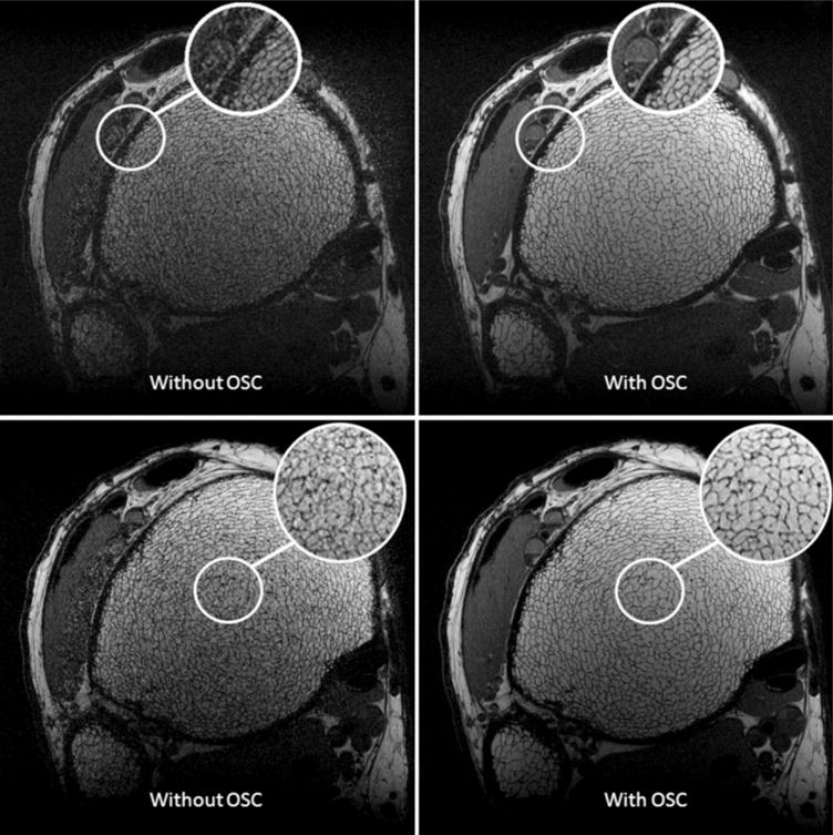
Two slices from the same 3D FSE-OSC scan of the distal tibia, acquired at 3 T with and without out-of-slab cancellation. Resolution is 137 × 137 × 410 μm3 in a scan time of 18.4 min.
As shown in Fig. 4, 3D FSE-OSC images provide a sharper depiction of the trabeculae than those obtained with 3D FLASE. The SNR (~10) was comparable between the two scans, acquired at 1.5 T, but the FSE-OSC image has noticeably thinner apparent trabeculae, presumably due to a narrower point-spread function in the readout direction, resulting from a higher readout bandwidth.
FIG. 4.
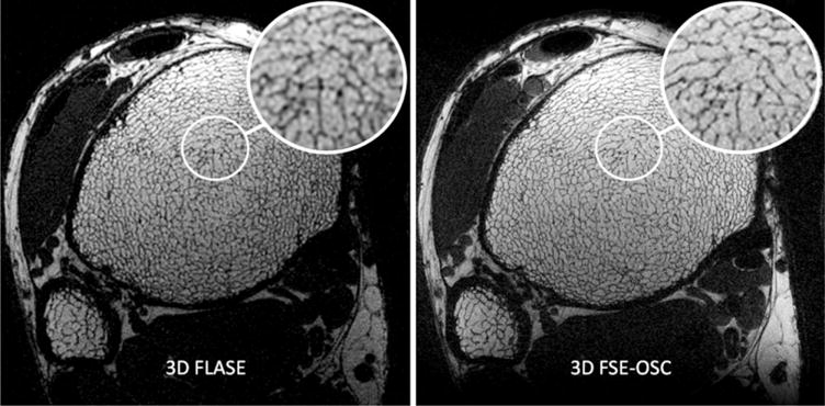
a: 3D FLASE image and (b) 3D FSE-OSC image of the distal tibia of the same subject acquired at 1.5 T. Resolution is 137 × 137 × 410 μm3 in a scan time of 15 min for FLASE and 18.4 min for FSE-OSC.
The use of linearly decreasing refocusing flip angles resulted in only a very slight signal loss as compared to using all 180° pulses, according to both simulation and experiment, as shown in Fig. 5. The signal decay curves match well between the oil phantom and the in vivo marrow scan, whereas the curve obtained from simulation does not match as well, in terms of its shape. This discrepancy could be due to the dependence of J-modulation dephasing on interpulse interval, well known to occur in triacyl glycerides (fat) (15,24). However, the simulation does accurately predict the relevant phenomenon, namely, the similarity of the decay rates for the various flip angle combinations. This is in contrast to the significant signal loss predicted in the early echoes when using, for example, all 90° pulses (see Fig. 6).
FIG. 5.
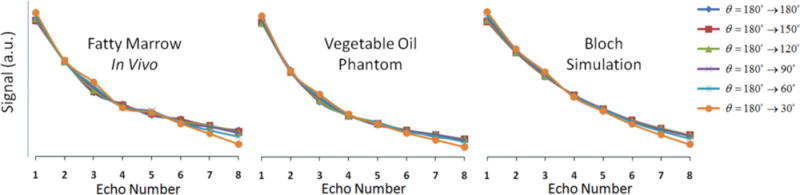
Measured and simulated signal decay curves as a function of echo number for various linearly decreasing refocusing flip-angle schemes.
FIG. 6.
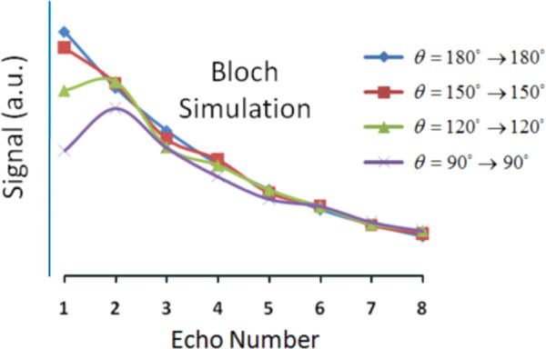
Simulated signal decay curves as a function of echo number for four constant refocusing flip-angle schemes.
The resulting relative SNR predictions and relative SAR levels (computed by Eq. 1) are displayed in Table 1. In the table, SNR was normalized so that unity corresponds to the case of zero decay (i.e., same signal for all echoes). For both simulation and experiment, very little change in relative SNR was observed when comparing flip angle schemes 180°→180°, 180°→150°, 180°→120°, 180°→90°, and 180°→60°, and there was only a 5–7% SNR drop for 180°→30°. However, relative SAR decreased significantly for these flip-angle schemes (~50% reduction in SAR for 180°→60°), indicating that a substantial decrease in SAR can be achieved without sacrificing SNR. On the other hand, there was a significant predicted SNR loss (~15%) for constant flip angles of 90°→90° in exchange for a 75% reduction in SAR.
Table 1.
Relative SAR vs Relative SNR for Various Flip-Angle Combinations According to Eqs. 1–2. Data was not collected for all flip-angle patterns
| Flip angles | Rel. SAR | Rel. SNR (Bloch) | Rel. SNR (oil) | Rel. SNR (marrow) |
|---|---|---|---|---|
| 180°→180° | 1 | 0.84 | 0.61 | 0.76 |
| 180°→150° | 0.84 | 0.84 | 0.61 | 0.76 |
| 180°→120° | 0.71 | 0.84 | 0.61 | 0.75 |
| 180°→90° | 0.59 | 0.84 | 0.62 | 0.75 |
| 180°→60° | 0.49 | 0.83 | 0.62 | 0.75 |
| 180°→30° | 0.41 | 0.78 | 0.58 | 0.72 |
| 150°→150° | 0.69 | 0.84 | . | . |
| 120°→120° | 0.44 | 0.81 | . | . |
| 90°→90° | 0.25 | 0.72 | . | . |
Figure 7 illustrates the performance of the pulse sequence at elevated field strengths, with more than doubling of SNR at 7 T relative to 3 T. We attribute this gain largely to the field strength increase since at both field strengths a four-element receive coil of identical design was used (as opposed to the two-element receive coil used at 1.5 T). A magnified view of the trabecular bone region in a 7-T FSE-OSC image with parallel imaging is provided in Fig. 8, illustrating high contrast between fatty marrow and bone tissue and delineation of trabecular architecture.
FIG. 7.
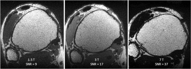
Images of the distal tibia of the same subject acquired with 3D FSE-OSC at three field strengths showing the enhanced SNR at 3 and 7 T relative to 1.5 T. Images in (b) and (c) were obtained with four-element receive coils of identical design. Inconsistency in orientation at 7 T is due to differences in immobilization setup at the different scanners. Muscle appears dark at 7 T because at this field strength the frequency difference between muscle and fat is greater than the bandwidth of the nonselective refocusing pulses. Resolution is 137 × 137 × 410 μm3 in a scan time of 18.4 min at 3 T and 7 T.
FIG. 8.
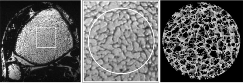
a: Single axial slice in a 3D FSE-OSC image of the distal tibia of a volunteer scanned at 7 T using parallel imaging. Resolution is 137 × 137 × 410 μm3 in a scan time of 10.2 min; (b) magnified view showing high contrast in a region of trabecular bone; (c) 3D rendering of skeletonized core.
Finally, the tradeoff between SNR and resolution can be seen in Fig. 9, in which back-to-back scans of the same subject are compared at anisotropic and isotropic resolution. Even though SNR is reduced in the latter, trabeculae deviating from the z-direction are clearly better visualized in the isotropic resolution images of the coronal reconstruction.
FIG. 9.
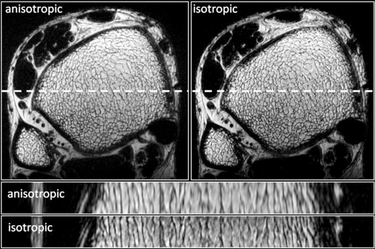
Transverse and longitudinal slices of the same distal tibia acquired using 3D FSE-OSC at anisotropic (137 × 137 × 410 μm3) and isotropic (160 × 160 × 160 μm3) resolutions. Scan times were 10.2 and 13 min for the anisotropic and isotropic protocols, respectively.
DISCUSSION
There is consensus that spin-echo techniques have significant advantages over gradient-echo-based techniques for imaging trabecular bone, both in terms of SNR efficiency and immunity to off-resonance artifacts (for example, in balance steady-state free precession (bSSFP) pulse sequences) (7,11). On the other hand, gradient-echo sequences are generally more straightforward to implement at very high field, which is why most of the musculoskeletal work reported at 7 T has been performed with either spoiled or refocused gradient-echo sequences (3,25).
Our data suggest the new FSE-based pulse sequence to have a number of favorable properties that make it suited for imaging of bone microarchitecture at peripheral skeletal locations dominated by fatty bone marrow. Specific features include a narrow point-spread function and high SNR efficiency, along with relative immunity to artifacts from induced magnetic field inhomogeneity. 3D FLASE, a standard spin-echo pulse sequence tailored for trabecular bone imaging and used extensively in some of the authors’ prior work at 1.5 T (26) and 3 T (9), has been found to be difficult to transfer to the 7-T field platform. SAR for FLASE easily exceeds Food and Drug Administration guidelines at this field strength, unless performance is compromised; for example, by increasing pulse repetition time. Substitution of 3D FLASE by the variable flip-angle 3D FSE sequence described in this work largely overcomes the SAR obstacles. Even before reducing flip angles, FSE-OSC affords a 40–60% SAR reduction relative to FLASE (depending on implementation). The primary reason for this reduction is that FLASE uses a large (~140°) selective pulse within every 80-ms repetition period, whereas FSE-OSC only involves a single selective 90° excitation pulse within every 500-ms repetition. The duty cycle for the nonselective refocusing pulses is slightly higher for FSE-OSC (8/500 ms >1/80 ms), but the shaped selective pulses contribute more to overall SAR in FLASE. Using reduced refocusing flip angles, a further decrease in SAR was achieved; for example, 41% additional reduction for the linear 180°→90° scheme according to Table 1. Increasing the duration of the refocusing pulses (e.g., to 1.5 ms) can also substantially lower SAR, with only a modest increase in echo time (or echo spacing). However, this also decreases the refocusing bandwidth, which is of particular concern at high field strength, where amplitude of static field inhomogeneity becomes more severe.
Exactly which set of pulse sequences and sequence parameters is compatible with scanning humans at 7 T depends on a number of factors, including the design of the transmit and receive coils, the geometry of the coils relative to patient anatomy, and the online safety calculations imposed by the scanner’s manufacturer. For example, Krug et al. (27) recently reported being able to run a variant of FLASE at the distal tibia on a 7-T GE scanner, using a somewhat reduced excitation flip angle. Our setup did not allow us to run such a sequence. Image quality for the 3D FSE-OSC images seems to be comparable to or to exceed the quality achieved using 3D FLASE. As pointed out earlier, one advantage of the technique is that it features a significantly higher readout bandwidth than FLASE (108 Hz/pixel compared with 32 Hz/pixel in our implementations). The FSE sequence thus provides a noticeably sharper depiction of trabecular structure for the same subject in Fig. 4. Despite the fact that out-of-slab cancellation requires twice as many repetitions as conventional FSE, overall scan time is still comparable to that of FLASE. This is because only 60% of ky-space is acquired, whereas such a reduction is not possible with FLASE since that sequence already involves partial Fourier encoding in the readout direction.
Although phase cycling has been used previously to deal with similar artifacts caused by the nonselective refocusing pulse of FLASE (28), the present technique is fundamentally different. Rather than moving artifacts to the edge of the field of view, as is done by Vasilic et al. (28), the present technique suppresses the unwanted signal, as described above. The use of such signal cancellation is necessary in the present situation as the artifact displacement technique does not work when more than one spin-echo is acquired within each repetition.
Unlike more common implementations of FSE sequences, involving longer echo trains with 100 or more readouts per repetition, our implementation uses only eight echoes per repetition. This is a consequence of the high resolution required in the present application leading to a relatively long echo spacing of 20 ms. Therefore, Alsop’s (14) analysis of variable flip angle FSE signal efficiency using pseudo-steady-state techniques does not apply here, given the short length of the echo train. Another difference between the target application and typical clinical uses of FSE is that achievement of a particular contrast (such as T2 weighting) is of no concern as there is only one signal-producing moiety, i.e., fat, that we wish to maximize (we essentially detect zero signal from the bone itself). For this reason, the center lines of k-space are always acquired at the beginning of the echo train.
Another potential advantage of the technique, although not yet utilized in this study, is the potential for improved motion detection throughout the scan. Navigator-based detection of motion is an integral capability of FLASE (10), achieved by acquiring additional navigator projections during the second half of each ~80 ms repetition. A similar strategy can be used with FSE-OSC, but because the repetition time is substantially longer (with >200 ms dead time per repetition), entire two-dimensional low-resolution images could be acquired rather than just one-dimensional projections. This technique has the potential to improve sensitivity for translational motion and perhaps could also detect in-plane rotational motion.
A limitation of the present technique is the relatively long scan time, since each line of k-space needs to be acquired twice. This limitation is particularly problematic at higher resolution, in which a larger number of phase-encoding steps are required. Therefore, future work will attempt to decrease scan time by (a) increasing the echo train length (perhaps to 12–16 echoes), (b) decreasing echo spacing, and (c) increasing the acceleration factor of parallel imaging.
In summary, the imaging strategy inherent to 3D FSE-OSC appears to have substantial advantages for spin-echo high-resolution imaging of trabecular microstructure in the distal extremities at field strengths from 1.5 to 7 T. Immunity to induced magnetic field perturbations, high SNR efficiency resulting from minimal J-modulation dephasing due to short interecho spacing of the RF refocusing train, and, last, low SAR should make the pulse sequence a useful alternative for the target application at very high magnetic field.
Acknowledgments
National Institutes of Health; Grant numbers: R01 AR41443, R01 AR53156, K25 EB007646, K25 EB01427.
APPENDIX
SNR Analysis for Variable Refocusing Flip-Angle Scheme
Here, we give an analytic explanation for the observation that there is only moderate signal loss when linearly decreasing variable flip angles are used for the refocusing pulses in the FSE echo train. More specifically, let θ1, θ2, …, θn be the refocusing flip angles with θ1 = 180° and θj + 1 = θj − δ, and let Sj be the complex signal level at the jth echo. In the case where δ = 0, the signal simply decays by T2 relaxation following the Carr-Purcell-Meiboom-Gill pulse sequence. For small δ, the signal intensity can be approximated by a first-order Maclaurin expansion:
| [3] |
Here, we show that the first-order term in this expansion vanishes, implying that, for small δ, the signal intensity can be very well approximated by the constant coefficient (i.e., by exponential decay).
We begin by noting that the mean complex signal intensity from a voxel at the jth echo is
| [4] |
where and are the unit vectors (1,0,0)T and (0,1,0)T, respectively, and Mj(ϕ) is the magnetization of an isochromat that precesses by an angle ϕ during each crusher gradient. We assume a uniform distribution of nutation angles across the voxel, and hence we integrate from 0 to 2π. Assuming instantaneous crushers and refocusing pulses, one can show that the magnetization satisfies the following recursion
| [5] |
with initial condition M0 = [0, M0, 0]T determined from the 90° RF pulse at time t = 0. The matrices Pj and Qj are given by the expressions
| [6] |
| [7] |
Here, Rz is a rotation around the z-axis, Ry is a rotation around the y-axis, I is the 3 × 3 identity matrix, and A and b are relaxation expressions from the Bloch equations
| [8] |
For simplicity, we ignore off-resonance effects in these expressions, but we point out that the final result will hold for arbitrary Larmor frequencies. The derivative of the mean signal intensity evaluated at δ = 0 is
| [9] |
Using a computer algebra system (CAS), it can be shown that
| [10] |
| [11] |
| [12] |
Since the integrals of sine and cosine vanish over one cycle and since Mj|δ = 0 has no ϕ dependence, the only nonzero term inside the integral of (9) is the first. For this reason, the derivative satisfies the recursion
| [13] |
where * denotes the complex conjugate. By induction on j, the derivative (i.e., the coefficient of the first-order term of the Maclaurin series) vanishes for all j.
References
- 1.Duyn JH, van Gelderen P, Li TQ, de Zwart JA, Koretsky AP, Fukunaga M. High-field MRI of brain cortical substructure based on signal phase. Proc Natl Acad Sci U S A. 2007;104:11796–11801. doi: 10.1073/pnas.0610821104. [DOI] [PMC free article] [PubMed] [Google Scholar]
- 2.Yacoub E, Shmuel A, Pfeuffer J, Van De Moortele PF, Adriany G, Ugurbil K, Hu X. Investigation of the initial dip in fMRI at 7 tesla. NMR Biomed. 2001;14:408–412. doi: 10.1002/nbm.715. [DOI] [PubMed] [Google Scholar]
- 3.Krug R, Carballido-Gamio J, Banerjee S, Stahl R, Carvajal L, Xu D, Vigneron D, Kelley DA, Link TM, Majumdar S. In vivo bone and cartilage MRI using fully-balanced steady-state free-precession at 7 tesla. Magn Reson Med. 2007;58:1294–1298. doi: 10.1002/mrm.21429. [DOI] [PubMed] [Google Scholar]
- 4.Friedrich KM, Chang G, Vieira RL, Wang L, Wiggins GC, Schweitzer ME, Regatte RR. In vivo 7.0-tesla magnetic resonance imaging of the wrist and hand: technical aspects and applications. Semin Musculoskel Radiol. 2009;13:74–84. doi: 10.1055/s-0029-1202942. [DOI] [PMC free article] [PubMed] [Google Scholar]
- 5.Wehrli FW. Structural and functional assessment of trabecular and cortical bone by micro magnetic resonance imaging. J Magn Reson Imaging. 2007;25:390–409. doi: 10.1002/jmri.20807. [DOI] [PubMed] [Google Scholar]
- 6.Majumdar S. Magnetic resonance imaging of trabecular bone structure. Top Magn Reson Imaging. 2002;13:323–334. doi: 10.1097/00002142-200210000-00004. [DOI] [PubMed] [Google Scholar]
- 7.Techawiboonwong A, Song H, Saha P, Wehrli F. Implications of pulse sequence in structural imaging of trabecular bone. J Magn Reson Imaging. 2005;22:647–655. doi: 10.1002/jmri.20432. [DOI] [PubMed] [Google Scholar]
- 8.Ma J, Wehrli FW, Song HK. Fast 3D large-angle spin-echo imaging (3D FLASE) Magn Reson Med. 1996;35:903–910. doi: 10.1002/mrm.1910350619. [DOI] [PubMed] [Google Scholar]
- 9.Magland JF, Wald MJ, Wehrli FW. Spin-echo micro-MRI of trabecular bone using improved 3D fast large-angle spin-echo (FLASE) Magn Reson Med. 2009;61:1114–1121. doi: 10.1002/mrm.21905. [DOI] [PMC free article] [PubMed] [Google Scholar]
- 10.Song HK, Wehrli FW. In vivo micro-imaging using alternating navigator echoes with applications to cancellors bone structural analysis. Magn Reson Med. 1999;41:947–953. doi: 10.1002/(sici)1522-2594(199905)41:5<947::aid-mrm14>3.0.co;2-m. [DOI] [PubMed] [Google Scholar]
- 11.Krug R, Han ET, Banerjee S, Majumdar S. Fully balanced steady-state 3D-spin-echo (bSSSE) imaging at 3 tesla. Magn Reson Med. 2006;56:1033–1040. doi: 10.1002/mrm.21037. [DOI] [PubMed] [Google Scholar]
- 12.Oshio K, Feinberg DA. GRASE (gradient-and spin-echo): a novel fast MRI technique. Magn Reson Med. 1991;20:344–349. doi: 10.1002/mrm.1910200219. [DOI] [PubMed] [Google Scholar]
- 13.Hennig J, Friedburg H. Clinical applications and methodological developments of the RARE technique. Magn Reson Imaging. 1988;6:391–395. doi: 10.1016/0730-725x(88)90475-4. [DOI] [PubMed] [Google Scholar]
- 14.Alsop DC. The sensitivity of low flip angle RARE imaging. Magn Reson Med. 1997;37:176–184. doi: 10.1002/mrm.1910370206. [DOI] [PubMed] [Google Scholar]
- 15.Henkelman RM, Hardy PA, Bishop JE, Poon CS, Plewes DB. Why fat is bright in RARE and fast spin-echo imaging. J Magn Reson Imaging. 1992;2:533–540. doi: 10.1002/jmri.1880020511. [DOI] [PubMed] [Google Scholar]
- 16.Allerhand A. Analysis of Carr-Purcell spin-echo NMR experiments on multiple-spin systems. J Chem Phys. 1966;44:1–9. [Google Scholar]
- 17.Wehrli FW. Structural and functional assessment of trabecular and cortical bone by micro magnetic resonance imaging. J Magn Reson Imaging. 2007;2:390–409. doi: 10.1002/jmri.20807. [DOI] [PubMed] [Google Scholar]
- 18.Hennig J, Nauerth A, Friedburg H. RARE imaging: a fast imaging method for clinical MR. Magn Reson Med. 1986;3:823–833. doi: 10.1002/mrm.1910030602. [DOI] [PubMed] [Google Scholar]
- 19.Le Roux P, Hinks RS. Stabilization of echo amplitudes in FSE sequences. Magn Reson Med. 1993;30:183–190. doi: 10.1002/mrm.1910300206. [DOI] [PubMed] [Google Scholar]
- 20.Busse RF. Reduced RF power without blurring: correcting for modulation of refocusing flip angle in FSE sequences. Magn Reson Med. 2004;51:1031–1037. doi: 10.1002/mrm.20056. [DOI] [PubMed] [Google Scholar]
- 21.Wang Z, Wang J, Detre JA. Improved data reconstruction method for GRAPPA. Magn Reson Med. 2005;54:738–742. doi: 10.1002/mrm.20601. [DOI] [PubMed] [Google Scholar]
- 22.Wright A, Wald M, Connick T, Magland J, Song H, Vasilic B, Lemdiasov R, Ludwig R, Wehrli F. 7T transmit four-channel receive array for high-resolution MRI of trabecular bone in the distal tibia. Proceedings of the 17th Meeting of the International Society for Magnetic Resonance in Medicine; Honolulu, HI. 2009. p. 443. [Google Scholar]
- 23.Magland J, Vasilic B, Wehrli FW. A virtual MRI scanner for simulating arbitrary pulse sequences on high-resolution virtual phantoms. Seattle, WA: ISMRM; 2006. p. 461. [Google Scholar]
- 24.Stables LA, Kennan RP, Anderson AW, Constable RT, Gore JC. Analysis of J coupling-induced fat suppression in DIET imaging. J Magn Reson. 1999;136:143–151. doi: 10.1006/jmre.1998.1628. [DOI] [PubMed] [Google Scholar]
- 25.Regatte RR, Schweitzer ME. Ultra-high-field MRI of the musculoskeletal system at 7.0T. J Magn Reson Imaging. 2007;25:262–269. doi: 10.1002/jmri.20814. [DOI] [PubMed] [Google Scholar]
- 26.Wehrli FW, Ladinsky GA, Jones C, Benito M, Magland J, Vasilic B, Popescu AM, Zemel B, Cucchiara AJ, Wright AC, Song HK, Saha PK, Peachey H, Snyder PJ. In vivo magnetic resonance detects rapid remodeling changes in the topology of the trabecular bone network after menopause and the protective effect of estradiol. J Bone Miner Res. 2008;23:730–740. doi: 10.1359/JBMR.080108. [DOI] [PMC free article] [PubMed] [Google Scholar]
- 27.Krug R, Carballido-Gamio J, Banerjee S, Burghardt AJ, Link TM, Majumdar S. In vivo ultra-high-field magnetic resonance imaging of trabecular bone microarchitecture at 7 T. J Magn Reson Imaging. 2008;27:854–859. doi: 10.1002/jmri.21325. [DOI] [PubMed] [Google Scholar]
- 28.Vasilic B, Song HK, Wehrli FW. Coherence-induced artifacts in large-flip-angle steady-state spin-echo imaging. Magn Reson Med. 2004;52:346–353. doi: 10.1002/mrm.20156. [DOI] [PubMed] [Google Scholar]