. 2015 Dec 23;4:e09580. doi: 10.7554/eLife.09580

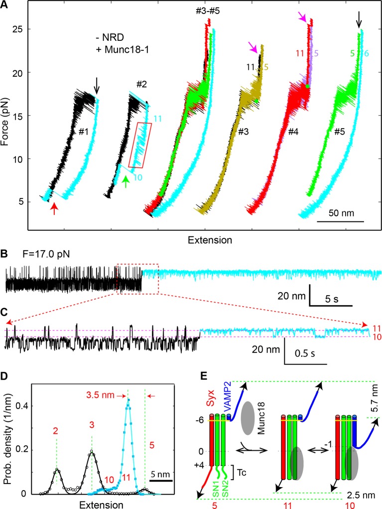
Figure 11. Munc18-1 stabilizes the half-zippered SNARE complex in an NRD-dependent manner and binds the t-SNARE complex to structure Tc in an NRD-independent manner.

(A) FECs of the SNARE complex lacking the NRD in the presence of 10 µM Munc18-1 in the solution. The rectangle marks the Munc18-1-mediated reversible transition in FEC #2 between states 10 and 11 illustrated in E. The FECs #3-#5 were obtained from the same SNARE complex in three consecutive rounds of pulling and relaxation. The FECs of different rounds overlap well (#3-#5) but are shifted along the x-axis for clarity (#3, #4, and #5). The states corresponding to some regions of FECs are indicated by their corresponding state numbers (Figures 11E and 1D). In FECs #3 and #4 the point of Munc18-1 binding is marked by a green dot. (B–C) Extension-time trajectories of the SNARE complex lacking an NRD under constant forces in the presence of 10 µM Munc18-1. The cyan regions indicate the Munc18-1-bound states (states 10 and 11). A close-up view of the region in B in the dashed rectangle is shown in (C). (D) Probability density distributions of the extensions of the Munc18-1-unbound states (black) and the Munc18-1-bound states (cyan) calculated from the corresponding regions in the trace shown in B. Different peaks represent different SNARE folding states numbered in red as in E and Figure 1D. (E) Diagram illustrating effects of Munc18-1 on assembly of the SNARE complex lacking an NRD and the associated average extension changes of the different states. FECs, force-extension curves; NRD, N-terminal regulatory domain.

DOI: http://dx.doi.org/10.7554/eLife.09580.026

Figure 11.

Figure 11—figure supplement 1. (A–B) Extension-time trajectory of the SNARE complex lacking an NRD in the presence of 10 μM Munc18-1 in the solution.

Figure 11—figure supplement 1.

The regions corresponding to the Munc18-1-bound states are colored cyan. The positions of different states are marked by red dashed lines. A close-up view of the region in (A) marked by a rectangle is shown in (B). (C) Probability density distributions (symbols) of the extensions corresponding to regions in A marked by black and cyan bars without and with Munc18-1 bound. The lines are best-fits of the distributions using a sum of three or one Gaussian function for the Munc18-1-unbound states or Munc18-bound states, respectively. NRD, N-terminal regulatory domain.
Figure 11—figure supplement 2. FECs of the SNARE complexes with the NRD (+NRD) obtained in the absence (−Munc18-1) or presence (+Munc18-1) of 10 µM Munc18-1.

Figure 11—figure supplement 2.

The region marked by a red rectangle shows the Munc18-1-mediated conformational transition between states 10 and 11 illustrated in Figure 11E. The green arrow indicates Munc18-1 displacement and SNARE reassembly. Compared with the FEC of the SNARE complex lacking the NRD (Figure 11A, #2), the results here suggest that even in the presence of the NRD, Munc18-1 could bypass the NRD to bind the SNARE complex in an NRD-independent manner. FECs, force-extension curves; NRD, N-terminal regulatory domain.
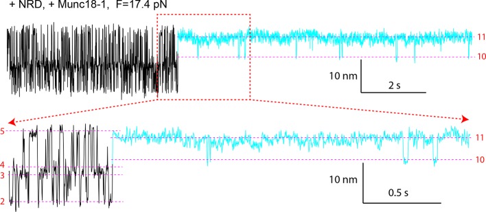
Figure 11—figure supplement 3. Extension-time trajectory of the wild-type SNARE complex with the NRD in the presence of 10 μM Munc18-1.

Figure 11—figure supplement 3.

The regions corresponding to the Munc18-1-bound states are colored cyan. The positions of different states are marked by red dashed lines. A close-up view of the region in the top trace marked by a rectangle is shown at the bottom. Compared with the trajectories for the SNARE complex lacking the NRD (Figure 11B,C), the trajectories here demonstrate that Munc18-1 could tightly bind t-SNARE and structure Tc in an NRD-independent manner, even in the presence of the NRD. NRD, N-terminal regulatory domain.