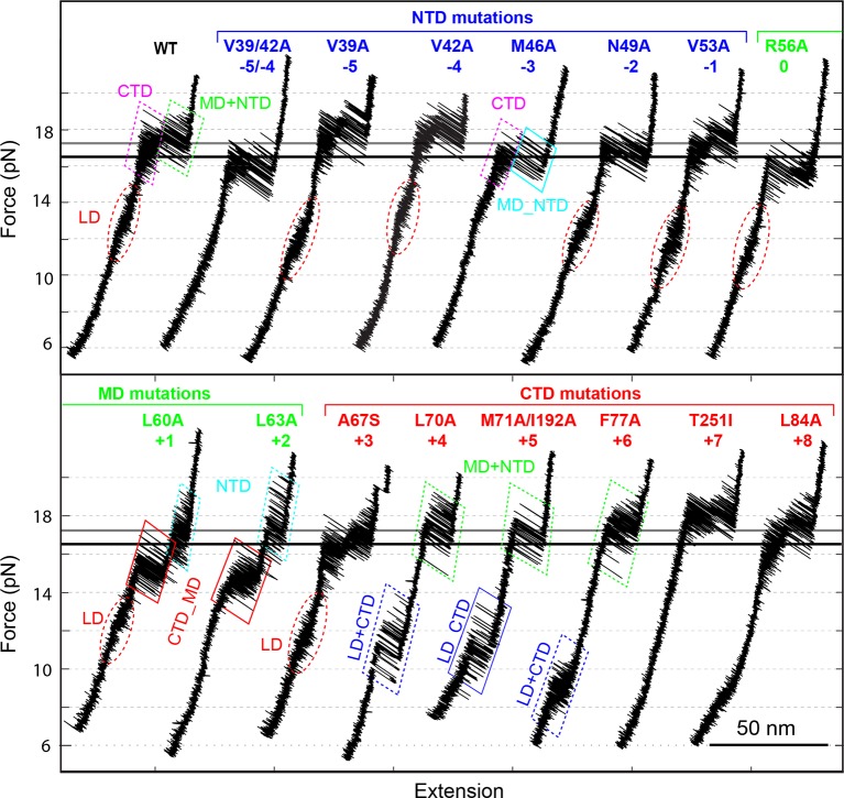
Figure 4. Position-dependent effects of layer mutations on SNARE assembly shown by the FECs of the wild-type and mutant SNARE complexes.
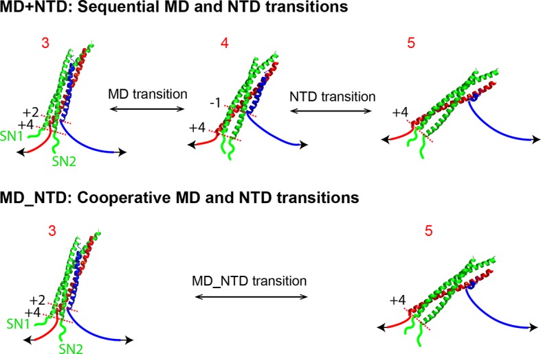
The SNARE mutations and their layer numbers are colored based on their associated domains: blue for NTD, green for MD, and red for CTD. While most mutants assemble sequentially as the wild type (WT), some mutants exhibit altered folding pathways, in which two neighboring domains fold and unfold cooperatively as combined domains. Throughout the text, two-state transitions of these new domains are marked by their associated subdomains connected by “_” (Figure 4—figure supplement 1). By comparison, overlapping sequential transitions are indicated by their associated domains linked by “+”. Different folding domains are marked by unique colored ovals or rectangles. Folding energies of the same domain in different SNARE complexes can be compared by the equilibrium forces of the domain transition. The black and gray horizontal lines indicate the average equilibrium forces of CTD (16.5 ± 0.8 pN) and MD+NTD (17.2 ± 0.8 pN), respectively, of the wild-type SNARE complex. CTD, C-terminal domain; FECs, Force-extensioncurves; MD, middle domain; NTD, N-terminal domain.
Figure 4—figure supplement 1. Comparison of sequential and cooperative domain transitions, using MD and NTD as an example.


