Abstract
Purpose
Functional neuroimaging of small cortical patches such as columns is essential for testing computational models of vision, but imaging from cortical columns at conventional 3T fields is exceedingly difficult. By targeting the visual cortex exclusively, we tested whether combined optimization of shape, coil placement, and electronics would yield the necessary gains in signal‐to‐noise ratio (SNR) for submillimeter visual cortex functional MRI (fMRI).
Method
We optimized the shape of the housing to a population‐averaged atlas. The shape was comfortable without cushions and resulted in the maximally proximal placement of the coil elements. By using small wire loops with the least number of solder joints, we were able to maximize the Q factor of the individual elements. Finally, by planning the placement of the coils using the brain atlas, we were able to target the arrangement of the coil elements to the extent of the visual cortex.
Results
The combined optimizations led to as much as two‐fold SNR gain compared with a whole‐head 32‐channel coil. This gain was reflected in temporal SNR as well and enabled fMRI mapping at 0.75 mm resolutions using a conventional GRAPPA‐accelerated gradient echo echo planar imaging.
Conclusion
Integrated optimization of shape, electronics, and element placement can lead to large gains in SNR and empower submillimeter fMRI at 3T. Magn Reson Med 76:321–328, 2016. © 2015 Wiley Periodicals, Inc.
Keywords: magnetic resonance imaging, phased‐array, fMRI, parallel imaging, shape optimization, ocular dominance columns, functional MRI, orientation columns, accelerated EPI
INTRODUCTION
Vision engages the largest portion of the human cerebral cortex and in multiple cortical areas is characterized by miniature functional units. For example, the two functional domains of the primary visual cortex, namely orientation and ocular preference, are represented by columns that span 0.77 mm to ∼1 mm 1, 2. Functional units of higher level areas are also marked by small subunits. Clusters approximating 1 mm in size have been reported in high‐level visual areas important for motion perception 3, 4 and similarly small sized modules are believed to represent complex object information in high‐level areas important for object recognition 5, 6. Noninvasive functional imaging of these small modules requires imaging at resolutions finer than 1 mm, a capability that is lacking at the large majority of research sites.
Using functional MRI (fMRI) and ultrahigh field strengths, a number of studies have demonstrated feasibility of mapping one of the subunits of the human visual cortex, namely ocular dominance columns 7, 8. For example, Yacoub and colleagues have demonstrated mapping ocular dominance columns in humans at 7T using a segmented spin echo acquisition scheme, but only in subjects with a flat calcarine sulcus 9. Goodyear and Menon successfully used a segmented gradient echo acquisition scheme at 4T to map out the ocular dominance columns 10. The methods used in these pioneering studies have seen very little extension, largely because of lack of access to ultrahigh‐field scanners and the challenges associated with high‐resolution image acquisition at such field strengths. Therefore, submillimeter imaging of the visual cortex has remained largely elusive for the bulk of this large field of neuroscientists.
Increasing field strength is a sure way to improve fMRI contrast, albeit an expensive one. At ultrahigh fields (∼7T), enough gain in sensitivity is achieved to allow for submillimeter fMRI assuming suitable gradients and radiofrequency (RF) hardware. However, such tools are generally unavailable to the majority of vision researchers, and their effective implementation is not straightforward (eg, segmented echo planar imaging [EPI] or three‐dimensional [3D] segmented acquisitions). Imaging smaller voxels places high demands on signal‐to‐noise ratio (SNR) that, aside from increasing field strength, can only be achieved through improvements in RF reception.
Optimizing coil design for the posterior head has been attempted on at least three previous occasions. Petridou et al. 11 and Adriany et al. 12 both have developed 16‐channel RF coils for high‐resolution functional imaging at 7T, with Petridou et al. demonstrating submillimeter resolution functional imaging but in a small constrained region of the posterior head. Barth and Norris 13 demonstrated very high‐resolution 3D functional imaging of the occipital cortex with a customized eight‐channel phased‐array receiver coil at 3T.
Visual cortex imaging presents a particular opportunity for high acceleration rates with good SNR. The bulk of the visual cortex is close to the skull and is constrained to the posterior of the head. Local increase of the receiver array density here could result in large gains in SNR and acceleration performance for this restricted region of the brain. In previous studies, we found an approximately 40% SNR gain when increasing the channel count from 32 to 64 with 65‐mm‐diameter loops 14 and gains of approximately 60% with when increasing the channel count to 96 with 50‐mm loops in the cortex near skull 15. Further reducing loop sizes, while still using room‐temperature conductors, forces new design choices in order to maintain sample‐noise dominance, namely that the coil housing has to closely follow the subject's head shape.
Because of the layout of the visual cortex and the restricted portion of the posterior skull that covers it, we sought to study the SNR gains of a densely packed open‐faced array consisting of 42‐mm elements for targeted imaging of this area. The design choice to pack the available channels to only cover the visual cortex restricts our imaging plane to those that are approximately tangential to the posterior skull, in contrast to previous whole‐head optimization approaches 14, 15, 16, 17. This integrated optimization led to a two‐fold increase in SNR for imaging the visual cortex compared with a commercial 32‐channel whole‐head coil and allowed for submillimeter functional imaging using single‐shot gradient echo EPI (GE‐EPI).
METHODS
Coil Construction
Coil Former and Housing
Because our goal was to focus and optimize the coil for visual cortex imaging, we were able to restrict the element placement to the head posterior. The resulting open‐faced topology is ideal for vision research as it allows for placement of optics (mirrors, lenses, patches, etc.). Sockets were placed on the housing face to facilitate attachment of such optics.
A critical component of our development was the identification and implementation of the optimal coil former shape. The coil former was modeled based on a nonlinear atlas of the International Consortium for Brain Mapping. The atlas used included a model of the neck as well, which allowed for optimal placement of the coils around the temporal lobe. A second consequence of this design was the subject comfort afforded by a contoured surface for resting the neck and head. The comfort afforded by the head and neck contours of our coil former allowed us to eliminate the need for padding. This further reduced the space between our elements and the head, contributing to greater sensitivity of the coil.
The layout of the overlapped circular coil elements was arranged by a hexagonal tiling pattern, which was printed onto the coil former together with standoffs to mount the preamplifiers and other coil electronic parts. Targeting the visual cortex as a region of interest, the tile size was adjusted appropriately to meet the desired number of 32 channels (Fig. 1). The loop diameter of 42 mm was derived from the size of the hexagon tiles, where the loop diameter is slightly larger than the diameter of the circle that inscribes the vertexes of the hexagon. All helmet parts, including its covers, were printed in polycarbonate plastic using a rapid prototyping 3D printer (Fortus 360; Stratasys Ltd., Eden Prairie, Minnesota, USA).
Figure 1.
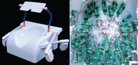
Dedicated 3T visual cortex coil for high‐resolution fMRI data acquisition. Thirty‐two coil elements are arranged in overlapping symmetry to target the visual cortex. The coil former follows the contour of the occipital pole and cerebellum to provide tight fitting coil elements at the region of‐interest. Special effort was made to create a comfortable head support to run fMRI with little or no foam cushioning.
Circuits
The 42‐mm loops were constructed from tin‐plated, 16‐gauge, oxygen‐free high thermal conductivity copper. Each loop contained bridges bent into the wire to allow the coil conductors to cross over. Each loop was symmetrically divided with two gaps, where the discrete RF components were placed [see schematic circuit in Keil et al. 16]. The discrete components were mounted on small FR4 circuit boards, manufactured with a rapid prototyping circuit router (T‐Tech‐7000; T‐Tech, Inc, Norcross, Georgia, USA) and then soldered to the loop conductor. These small circuit boards minimized mechanical stress between the loop wires and the ceramic capacitors (Series 11; Voltronics, Danville, New Jersey, USA). The tuning capacitor circuit board contained a variable capacitor (GFX2700NM; Sprague Goodman, Westbury, New York, USA) to fine‐tune the loop resonance to 123.25 MHz. The output circuit‐board incorporated a capacitive voltage divider to impedance‐match the element's output to an optimized noise‐matched impedance, Z NM, required by the preamplifier (Siemens AG, Healthcare Sector, Erlangen, Germany). Additionally, the output circuit board used an active detuning circuit across the match capacitor consisting of a hand‐wound inductor L and a PIN diode (MA4P4002B‐402; Macom, Lowell, Massachusetts, USA) to provide a parallel resonant circuit at the Larmor frequency when the diode is forward‐biased. Thus, when the PIN diode was forward‐biased (transmit mode), the resonant parallel LC circuit inserted a high impedance in series with the coil loop, blocking current flow at the Larmor frequency during transmit. Preamplifier decoupling was achieved by first transforming the preamplifier's input impedance to a low impedance (short‐circuit) across detuning trap, which turned this parallel LC circuit into a high‐serial impedance in the coil loop. Preamplifier outputs were connected to a cable trap to suppress common mode currents and to avoid interaction with the RF transmit system. More details of the RF coil circuitry are given in Keil et al. 16.
Bench Measurements
Bench measurements verified the element tuning, active detuning, nearest‐neighbor coupling, and preamplifier decoupling for each coil element. Additionally, the ratio of unloaded‐to‐loaded quality factor (Q U/Q L) was obtained with a coil element under test placed both external to the array assembly and within the populated but detuned array.
Active detuning was measured with an S 21 measure between two decoupled (∼80 dB) inductive probes slightly coupled to the array element under test. Nearest neighbor coupling was measured using a direct S 21 measurement between pairs of elements using coaxial cables connected directly to the preamplifier sockets of the two elements under test. The overlap between nearest neighbors was empirically optimized, while watching the S 21 measure between the two loops under test. When measuring the S 21 between an adjacent pair, all other elements of the array were detuned.
The preamplifier decoupling of a given loop was measured with all other loops detuned. Preamplifier decoupling was measured as the change in the double‐probe S 21 when the preamplifier socket was first terminated with the powered low impedance preamplifier and second with a power‐matched terminator 18.
MRI Data Acquisition and Reconstruction
Data were acquired on a 3T clinical MRI Siemens scanner (MAGNETOM, Trio a Tim system, Siemens AG Healthcare Sector, Erlangen, Germany) with 40 mT/m maximum amplitude gradient strength and a maximum slew rate of 200 mT/m/ms. SNR, g‐factor, and noise correlation measurement were obtained from in vivo scans. For all measurements, the body coil was used for transmit. These measurements were compared with a commercially available 32‐channel whole‐head coil using the same subject with identical slice prescription (atlas‐based auto‐align). GE images were used to acquire an SNR map using the following parameters: repetition time (TR) = 300 ms; echo time (TE) = 15 ms; flip angle (FA) = 20°; slice thickness = 3 mm; number of slices = 35; matrix = 64 × 64; field of view (FOV) = 192 × 192 mm2; and bandwidth (BW) = 200 Hz/pixel. Noise covariance information was acquired using the same pulse sequence but with no RF excitation. The SNR maps were calculated using the noise‐covariance weighted root sum‐of‐squares of the individual channel images, where the weights utilize coil sensitivity maps and noise covariance information 19, 20. The SNR data were coregistered to a T1‐weighted multiecho MPRAGE 21 acquired using a whole‐head coil (TR = 2.51 s; TI = 1.2 s; FA = 7°; four echoes with TE = 1.64 ms, 3.5 ms, 5.36 ms, and 7.22 ms; matrix = 192 × 192 × 176 with 1 mm isotropic voxel size; BW = 651 Hz/pixel; R = 3). A 3D surface representation was reconstructed from the MEMPRAGE image using FreeSurfer 22, 23 and was used to visualize the SNR data on the cortical surface. The SENSE g‐factor maps were calculated from the complex coil sensitivities and noise covariance matrix to assess noise amplification in parallel image reconstruction 24. For g‐factor calculations, an oblique‐coronal slice prescription was used, similar to that applied in visual cortex fMRI acquisition schemes.
Coil stability was evaluated on a spherical phantom using single‐shot GE‐EPI time series (FOV = 200 × 200 mm2; TR = 1000 ms; TE = 30 ms; FA = 90°; BW = 2298 Hz/pixel; matrix = 64 × 64; slice thickness = 5 mm; number of slices = 16; 500 measurements). Peak‐to‐peak variation in the signal intensity was averaged over a 15‐pixel square region of interest positioned in the center of the phantom after the removal of linear and quadratic trends from the time series 25.
Temporal SNR (tSNR) was measured at two resolutions—1 mm and 2 mm isotropic—using single‐shot GE‐EPI acquisitions with GRAPPA acceleration. For the 1‐mm images, acquisition parameters were TR = 250 ms; TE = 33 ms; FA = 33°; 3 × 1‐mm slices acquired interleaved with 0.1 mm slice gap; FOV = 128 × 128 mm; matrix = 128 × 128; BW = 1086 Hz/pixel; echo spacing = 1.05 ms; and R = 3 acceleration with fat saturation. For the 2‐mm images, the same parameters were used with the following exceptions: matrix = 64 × 64; 3 × 2‐mm slices acquired with a 0.2‐mm slice gap. During each measurement, 320 volumes were acquired from the posterior occipital cortex while subjects viewed two blocks of 10 s visual stimulation, followed by 30 s of rest. The 240 volumes corresponding to the rest period of the hemodynamic response function were used for the tSNR measurements 26. The tSNR measurements were performed on the visual cortex‐optimized coil as well as the vendor‐supplied whole‐head 32‐channel coil; therefore, a total of four tSNR measurements were performed. To calculate tSNR, measurement volumes were first assessed for motion using AFNI's 27 3dvolreg motion correction tool, but motion was negligible in all runs, therefore motion correction was not applied. The mean of all images was then divided by the standard deviation of the images voxel‐wise. A manually drawn mask was used to exclude nonbrain voxels in the tSNR estimates.
The coil underwent a battery of tests that assessed safety for the subjects. To check whether active detuning during transmit phase was sufficient, the power needed to achieve the adjustment flip angle (180°) was measured in a phantom with and without the receive coil present. The ratio of these two measures was required to be between 0.9 and 1.1. The coil was also tested for heating. After switching off the SAR monitor and the gradient stimulation monitor, measurements were made of the temperature increase in the coil caused by RF transmit power being absorbed by the receive circuitry or heating by induced currents from the gradient switching. The detuned coil and phantom were scanned for 15 min with a body coil B1‐field of 30 μT applied at a 10% duty cycle and repetition time of 60 ms, an RF power level well above the SAR limit.
Submillimeter functional MRI at 3T was performed successfully using the visual cortex coil. For these fMRI acquisitions, a standard single‐shot GE‐EPI protocol was used to acquire images at 0.75 mm isotropic resolution with the following parameters: TR = 3000 ms; TE = 31 ms; FA = 90°; fat saturation; FOV = 160 mm × 160 m; matrix = 214 × 214; partial Fourier = 6/8; R = 4; and BW = 834 Hz/pixel. The images were reconstructed with standard online Siemens EPI and GRAPPA reconstruction. During the acquisition, the subject viewed a stimulus that was back‐projected on a translucent screen at the back of the scanner bore and reflected onto the eyes with a mirror placed just above the head coil. The stimulus consisted of an alternating pattern of 30 s of the movie Despicable Me with a 30‐s blank screen, with the alternation occurring five times. The images were slice‐time and motion‐corrected but were not smoothed. Statistical parametric maps were generated using AFNI's 3dDeconvolve program, which fits a model time series consisting of the canonical hemodynamic response function convolved with the movie onsets. The exact same procedure was followed for acquiring and analyzing comparison data from the 32‐channel whole‐head vendor‐supplied coil. In order to directly compare the two datasets, the results of the analysis from the visual cortex coil were rigidly coregistered to the whole‐head data.
RESULTS
The 42‐mm‐diameter coil elements showed a Q U/Q L‐ratio of 273/114 = 2.3 and 258/123 = 2.1, for a single isolated coil loop and a loop surrounded by its six nonresonant neighboring elements, respectively. The Q U/Q L ratio showed that the sample and component losses contributed almost equally to the image noise for these small diameter loops with limited tissue volume under each element. In addition, upon sample loading, a frequency drop of 0.3 MHz was measured with an isolated coil element.
All safety tests were passed successfully. For assessing active detuning efficiency, the ratio of transmitted power with and without the coil present was 1.03. The temperature increase in the coil caused by RF transmit power being absorbed by the receive circuitry or heating by induced currents from the gradient switching was <2°C. Stability test indicated a peak‐to‐peak variation of 0.2% over a 15 × 15 pixel ROI for 500 time points for 3 × 3 × 5 mm resolution EPI (after detrending).
Figure 2 shows a representative noise correlation matrix obtained from noise‐only phantom images. The noise correlation ranged from 0.2% to 42% with an average of 13%. Bench tests showed a range of decoupling between nearest neighbor elements from −12 dB to −21 dB with an average of −14 dB, which is improved by additional reduction of 19 dB via preamplifier decoupling. Furthermore, active PIN diode detuning resulted in 40 dB isolation between tuned (PIN diode forward‐biased) and detuned states (PIN diode reverse‐biased) of the array elements.
Figure 2.
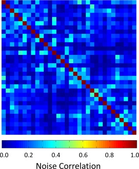
Noise correlation matrix of the constructed 32‐channel array coil. The noise correlation ranges from 0.2% to 42% (13% average).
Figure 3 shows volume‐ and surface‐based maps of the obtained visual cortex SNR of the constructed coil and a commercial 32‐channel whole brain array coil. The representative sagittal slice SNR map comparison was measured with the same subject. In the target region, the dedicated visual cortex coil shows a two‐fold SNR improvement compared with the whole‐head 32‐channel coil. The surface‐based SNR map depicts the SNR gain of the visual cortex coil over the whole‐head coil.
Figure 3.
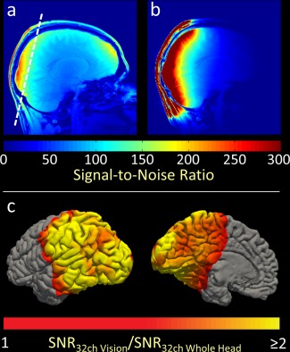
Volume‐ and surface‐based visualization of in vivo SNR comparison of the visual cortex coil compared with a vendor‐supplied 32‐channel whole‐head coil. (a) SNR map of the whole head. The dashed line indicates the slice position for the g‐factor maps (see Fig. 4). (b) SNR map of the visual cortex coil. (c) SNR gain of the visual cortex coil as a ratio of the whole head coil SNR. The optimizations employed in the visual cortex coil resulted in a two‐fold SNR improvement near the coils, and approximately 50% improvement elsewhere in the visual cortex.
Figure 4 shows the comparison of inverse local g‐factor maps in an oblique‐coronal plane (as typically used for visual cortex fMRI) for one‐dimensional accelerations derived from coil sensitivity profiles and noise correlations from the in vivo measurements. The dedicated 32‐channel visual cortex coil produces overall lower g‐factors, roughly providing a 1.5 additional unit of acceleration for a given noise amplification factor, when compared with a 32‐channel head coil. For example, for R = 3 the constructed coil showed an average of 28% less noise amplification. The combination of reduced g‐factor and improved occipital cortical SNR translates to improved image quality in visual fMRI studies.
Figure 4.
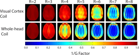
Coronal‐like maps of 1/g‐factors obtained from the dedicated 32‐channel visual cortex coil and the 32‐channel head coil. The visual cortex coil performs considerably better than the whole‐head coil in its target region, allowing for between 1‐2 higher units of acceleration than the whole‐head coil.
Figure 5 shows the mean and maximum tSNR estimates for 1 mm and 2 mm isotropic resolution GE‐EPI acquisitions made with the vendor‐supplied 32‐channel coil and the visual cortex coil, as well as representative tSNR maps for each of those measurements. Temporal SNR in the posterior occipital cortex was approximately two‐fold higher on average with the visual cortex coil than the vendor‐supplied whole‐head coil. The maximum SNR estimates in this brain area are even higher—approximately 2.5‐fold greater in this cortical area with the optimized coil than with the standard 32‐channel whole‐head coil. The tSNR gain from the whole‐head to the visual cortex coil was higher for the 1‐mm acquisitions, likely due to decreased partial volume effects at the higher resolution.
Figure 5.
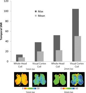
tSNR comparison at 2 mm and 1 mm between the visual cortex coil and the commercial 32‐channel whole‐head coil. The visual cortex coil generally exhibited greater than a two‐fold increase in tSNR when comparing it with the mean or the maximum tSNR of the same region imaged with the whole‐head coil. Bottom row: Temporal SNR maps for one slice at 1 mm and 2 mm in the posterior visual cortex imaged with the whole‐head coil versus the visual cortex coil along with relevant color scales.
Submillimeter fMRI at 0.75 mm isotropic resolution yielded excellent image quality (Fig. 6, top row) and was usable for fMRI measurements. Without spatial smoothing, activity‐related signal changes were observed in the posterior occipital cortex in response to the 30 s on, 30 s off movie stimulus, suggesting that even with such small voxels, fMRI responses can be robustly measured with appropriate hardware at 3 T (Figure 6, bottom row). In contrast to the robust fMRI signal change that was measureable with the visual cortex coil, the same paradigm resulted in negligible pattern of activity when measured using the whole‐head coil (Fig. 6, bottom row).
Figure 6.
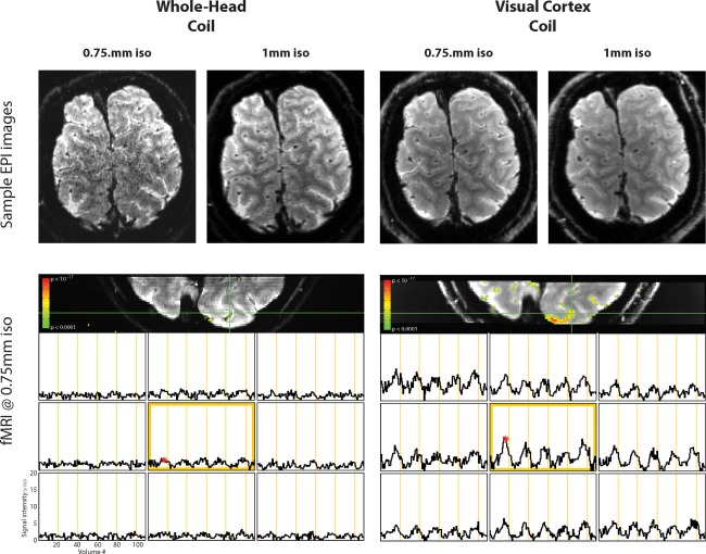
Images from the commercial 32‐channel whole‐head coil and the visual cortex coil measured at 0.75 mm and 1 mm, as well as BOLD fMRI at 0.75 mm isotropic resolution on both coils. Although fMRI activity measured with the visual cortex coil at 0.75 mm was robust, a similar pattern was not observed for the whole‐head coil.
DISCUSSION
In this study, we constructed and characterized a shape‐optimized, visual cortex–targeted 32‐channel receiver array coil. Through weighted design choices that sacrifice flexible imaging planes for higher SNR and better acceleration, dense packing of small loops covering the visual cortex yielded a doubling of SNR in this region of the brain. The SNR gains were sufficient for submillimeter fMRI at 3T, opening the way for new studies on the microstructure of cortical visual function.
Given that previous 64‐ and 96‐channel studies with dense arrays yielded only between 40% and 60% cortical SNR gain, respectively, over a 32‐channel whole‐head, we had not anticipated a doubling of SNR with the visual cortex coil. The previous coils 14, 15 utilized loops that were of similar material and electronics, although our 42‐mm‐diameter loops are slightly smaller compared with the 96‐channel whole‐head coil 15. However, our previous whole‐head coils did not specifically optimize the shape of the housing to the extent carried out here. Therefore, we suggest that shape optimization can be at least as important as electronic considerations in boosting SNR in phased‐array coil design, particularly when one region of the brain is targeted at the cost of the flexibility of whole‐head imaging.
The 32‐channel visual cortex coil was designed for stability in both highly accelerated and high‐resolution functional imaging on a clinical 3T scanner for robust daily use. The array coil performance was evaluated via 1) bench‐level measurements such as Q U/Q L‐ratios, tuned‐detuned isolation, and neighbor coupling; 2) system‐level validations, which included component heating, transmit field interactions, and stability measurements; and 3) in vivo brain performance tests, which were performed by pixel‐wise SNR maps, g‐factor maps, noise correlation, tSNR, and submillimeter functional imaging.
A number of technical issues arise in the implementation of large channel‐count arrays employing relatively small element sizes (such as the 42‐mm‐diameter elements used here). In particular, the interelement decoupling becomes more difficult and time‐consuming as the element density increases. In addition, maintaining a sufficient Q U/Q L ratio becomes problematic. For example, while a whole‐head 32‐channel adult coil with a loop diameter of ∼90 mm can be constructed out of flexible circuit material, array coils with smaller sized elements show significant eddy current losses in the flat circuit board conductors of the neighboring elements, leading to a lower Q U/Q L ratio and diminished SNR 15, 28. Spatially sparse wire conductors and carefully chosen location of the preamplifiers and their motherboards with at least 30 mm from the loop elements reduces the losses in these copper components. Also, the ability to mechanically optimize the overlap between two neighboring loops by bending the wire facilitated the element decoupling procedure. Despite these optimizations, the unloaded Q of a given loop was measurably diminished when the loop under test was placed in an array configuration, suggesting that losses within the conductors of neighboring elements were still present. Nonetheless, the Q U/Q L = 2.1 for our coil suggests that electronic noise and the sample noise is equally distributed. A frequency drop of 0.3 MHz upon sample loading, measured with an isolated coil element (no neighbors present) of the 32‐channel coil, indicates some imbalances in how the sample and coil interact through electric and magnetic fields. This source of loss could be compensated with more equally distributed series tuning capacitors to further balance the electrical field around the loop. When loop sizes are small, additional series capacitors increase the effective series loop resistance 28, which in turn reduces SNR. The practical implementation of higher capacitor counts in high‐density array coils is also seriously challenging.
To image the function of small brain structures accurately, both high‐resolution scans and high SNR values are required. The BOLD‐fMRI contrast‐to‐noise ratio can be expressed as the product of the tSNR and the fractional change in relaxivity, R2*, during activation (ΔR2*/R2*) 29. Because the latter is determined mainly by biology, tSNR can be increased by improving acquisition hardware and/or field strength. The latter is both expensive and introduces its own challenges, while hardware optimization can be economical and effective, albeit restricted to a region of interest, in this case, the visual cortex. For high‐resolution accelerated scans, this means optimizing the intrinsic detection sensitivity (the effective B 1 − of the array coil), the g‐factor of the accelerated image while maintaining temporal stability.
Temporal stability is critical for highly accelerated imaging. For example, GRAPPA kernels are trained on multishot data to match the echo spacing of the accelerated data, and multishot sequences are intrinsically more sensitive to temporal instabilities than single‐shot sequences. This means that temporal instabilities inadvertently reduce tSNR both directly by modulating the single‐shot data and indirectly by increasing the g‐factor. Therefore, high‐resolution fMRI acquisitions using GRAPPA demand both maximal stability and sufficient image encoding capabilities to allow for detection of small ΔR2*/R2*.
The developed coil provides both a high time course stability of 0.2% peak‐to‐peak and overall low noise amplification when using fMRI‐relevant acceleration factors (R = 3, R = 4). Furthermore, the high SNR of the multiple small elements can be invested into submillimeter resolution, which brings the tSNR into a thermal noise dominated regimen by reducing the physiological noise, the amplitude of which scales with the MR signal strength in a given voxel 30. Therefore, acquisitions at higher resolutions have the additive advantage of reducing the associated time series artifacts caused by unwanted physiological noise contributions (cardiac and respiratory fluctuations) resulting in increased sensitivity. In addition to increased localized activations and the ability to resolve the visual cortex in its smallest modules, higher‐resolution fMRI acquisitions allow for less through‐plane signal dephasing, limited partial volume effects, and improved biological point spread function of the BOLD effect. This isolation process and the achieved high spatial specificity ultimately allow us a better understanding of intrinsic properties of functional networks in both stimulus‐related and spontaneous neural activities.
CONCLUSION
By optimizing the shape of the MRI coil to optimally fit the head, and by guiding the placement of small‐diameter elements with a surface‐based 3D model of the brain in the skull, we were able to realize substantial gains in SNR and performance for imaging of the human visual cortex. The coil performance was adequate for functional imaging in the submillimeter range using a conventional GRAPPA‐accelerated GE‐EPI sequence.
ACKNOWLEDGMENTS
We thank Andrew Janke, Vladimir Fonov, and Louis Collins for help with head image data.
RF is a shareholder in Güdform Neurotechnology Inc, a company that is seeking to commercialize the Visual Cortex coil.
Correction added after online publication 26 February 2016. Due to a publisher's error, the authors' disclosure statement was omitted from their article and has been added in this version.
REFERENCES
- 1. Yacoub E, Harel N, Ugurbil K. High‐field fMRI unveils orientation columns in humans. Proc Natl Acad Sci USA 2008;105:10607–10612. [DOI] [PMC free article] [PubMed] [Google Scholar]
- 2. Adams DL, Sincich LC, Horton JC. Complete pattern of ocular dominance columns in human primary visual cortex. J Neurosci 2007;27:10391–10403. [DOI] [PMC free article] [PubMed] [Google Scholar]
- 3. Albright TD, Desimone R, Gross CG. Columnar organization of directionally selective cells in visual area MT of the macaque. J Neurophysiol 1984;51:16–31. [DOI] [PubMed] [Google Scholar]
- 4. Zimmermann J, Goebel R, De Martino F, van de Moortele P‐F, Feinberg D, Adriany G, Chaimow D, Shmuel A, Uğurbil K, Yacoub E. Mapping the organization of axis of motion selective features in human area MT using high‐field fMRI. PLoS One 2011;6:e28716. [DOI] [PMC free article] [PubMed] [Google Scholar]
- 5. Grill‐Spector K, Sayres R, Ress D. High‐resolution imaging reveals highly selective nonface clusters in the fusiform face area. Nat Neurosci 2006;9:1177–1185. [DOI] [PubMed] [Google Scholar]
- 6. Wang G, Tanaka K, Tanifuji M. Optical imaging of functional organization in the monkey inferotemporal cortex. Science 1996;272:1665–1668. [DOI] [PubMed] [Google Scholar]
- 7. Ogawa S, Lee TM, Kay AR, Tank DW. Brain magnetic resonance imaging with contrast dependent on blood oxygenation. Proc Natl Acad Sci USA 1990;87:9868–9872. [DOI] [PMC free article] [PubMed] [Google Scholar]
- 8. Kwong KK, Belliveau JW, Chesler DA, Goldberg IE, Weisskoff RM, Poncelet BP, Kennedy DN, Hoppel BE, Cohen MS, Turner R. Dynamic magnetic resonance imaging of human brain activity during primary sensory stimulation. Proc Natl Acad Sci USA 1992;89:5675–5679. [DOI] [PMC free article] [PubMed] [Google Scholar]
- 9. Yacoub E, Shmuel A, Logothetis N, Uğurbil K. Robust detection of ocular dominance columns in humans using Hahn Spin Echo BOLD functional MRI at 7 Tesla. Neuroimage 2007;37:1161–1177. [DOI] [PMC free article] [PubMed] [Google Scholar]
- 10. Goodyear BG, Menon RS. Brief visual stimulation allows mapping of ocular dominance in visual cortex using fMRI. Hum Brain Mapp 2001;14:210–217. [DOI] [PMC free article] [PubMed] [Google Scholar]
- 11. Petridou N, Italiaander M, van de Bank BL, Siero JC, Luijten PR, Klomp DW. Pushing the limits of high‐resolution functional MRI using a simple high‐density multi‐element coil design. NMR Biomed 2013;26:65–73. [DOI] [PubMed] [Google Scholar]
- 12. Adriany G, Waks M, Tramm B, Schillak S, Yacoub E, de Martino F, Van de Moortele P‐F, Naselaris T, Olman C, Vaughan T, Ugurbil K. An Open Faced 4 ch. Loop Transmit/16 ch. Receive Array Coil for HiRes fMRI at 7 Tesla. In Proceedings of the 20th Annual Meeting of ISMRM, Melbourne, Victoria, Australia, 2012. p. 429.
- 13. Barth M, Norris DG. Very high‐resolution three‐dimensional functional MRI of the human visual cortex with elimination of large venous vessels. NMR Biomed 2007;20:477–484. [DOI] [PubMed] [Google Scholar]
- 14. Keil B, Blau JN, Biber S, Hoecht P, Tountcheva V, Setsompop K, Triantafyllou C, Wald LL. A 64‐channel 3T array coil for accelerated brain MRI. Magn Reson Med 2013;70:248–258. [DOI] [PMC free article] [PubMed] [Google Scholar]
- 15. Wiggins GC, Polimeni JR, Potthast A, Schmitt M, Alagappan V, Wald LL. 96‐Channel receive‐only head coil for 3 Tesla: design optimization and evaluation. Magn Reson Med 2009;62:754–762. [DOI] [PMC free article] [PubMed] [Google Scholar]
- 16. Keil B, Alagappan V, Mareyam A, McNab JA, Fujimoto K, Tountcheva V, Triantafyllou C, Dilks DD, Kanwisher N, Lin W, Grant PE, Wald LL. Size‐optimized 32‐channel brain arrays for 3 T pediatric imaging. Magn Reson Med 2011;66:1777–1787. [DOI] [PMC free article] [PubMed] [Google Scholar]
- 17. Wiggins GC, Triantafyllou C, Potthast A, Reykowski A, Nittka M, Wald LL. 32‐channel 3 Tesla receive‐only phased‐array head coil with soccer‐ball element geometry. Magn Reson Med 2006;56:216–223. [DOI] [PubMed] [Google Scholar]
- 18. Reykowski A, Wright SM, Porter JR. Design of matching networks for low noise preamplifiers. Magn Reson Med 1995;33:848–852. [DOI] [PubMed] [Google Scholar]
- 19. Kellman P, McVeigh ER. Image reconstruction in SNR units: a general method for SNR measurement. Magn Reson Med 2005;54:1439–1447. [DOI] [PMC free article] [PubMed] [Google Scholar]
- 20. Roemer PB, Edelstein WA, Hayes CE, Souza SP, Mueller OM. The NMR phased array. Magn Reson Med 1990;16:192–225. [DOI] [PubMed] [Google Scholar]
- 21. Van der Kouwe AJW, Benner T, Salat DH, Fischl B. Brain morphometry with multiecho MPRAGE. Neuroimage 2008;40:559–569. [DOI] [PMC free article] [PubMed] [Google Scholar]
- 22. Dale AM, Fischl B, Sereno MI. Cortical surface‐based analysis. I. Segmentation and surface reconstruction. Neuroimage 1999;9:179–194. [DOI] [PubMed] [Google Scholar]
- 23. Fischl B, Sereno MI, Dale AM. Cortical surface‐based analysis. II: Inflation, flattening, and a surface‐based coordinate system. Neuroimage 1999;9:195–207. [DOI] [PubMed] [Google Scholar]
- 24. Pruessmann KP, Weiger M, Scheidegger MB, Boesiger P. SENSE: sensitivity encoding for fast MRI. Magn Reson Med 1999;42:952–962. [PubMed] [Google Scholar]
- 25. Weisskoff RM. Simple measurement of scanner stability for functional NMR imaging of activation in the brain. Magn Reson Med 1996;36:643–645. [DOI] [PubMed] [Google Scholar]
- 26. Murphy K, Bodurka J, Bandettini PA. How long to scan? The relationship between fMRI temporal signal to noise ratio and necessary scan duration. Neuroimage 2007;34:565–574. [DOI] [PMC free article] [PubMed] [Google Scholar]
- 27. Cox RW. AFNI: software for analysis and visualization of functional magnetic resonance neuroimages. Comput Biomed Res 1996;29:162–173. [DOI] [PubMed] [Google Scholar]
- 28. Kumar A, Edelstein WA, Bottomley PA. Noise figure limits for circular loop MR coils. Magn Reson Med 2009;61:1201–1209. [DOI] [PMC free article] [PubMed] [Google Scholar]
- 29. Wald LL, Polimeni JR, 2015. High‐speed, high‐resolution acquisitions In Toga AW, editor. Brain mapping: an encyclopedic reference. San Diego, CA: Academic Press. [Google Scholar]
- 30. Triantafyllou C, Hoge RD, Krueger G, Wiggins CJ, Potthast A, Wiggins GC, Wald LL. Comparison of physiological noise at 1.5 T, 3 T and 7 T and optimization of fMRI acquisition parameters. Neuroimage 2005;26:243–250. [DOI] [PubMed] [Google Scholar]


