Abstract
Cone beam computed tomography (CBCT) systems with rotational gantries that have standard flat panel detectors (FPD) are widely used for the 3D rendering of vascular structures using Feldkamp cone beam reconstruction algorithms. One of the inherent limitations of these systems is limited resolution (<3 lp/mm). There are systems available with higher resolution but their small FOV limits them to small animal imaging only.
In this work, we report on region-of-interest (ROI) CBCT with a high resolution CMOS detector (75 μm pixels, 600 μm HR-CsI) mounted with motorized detector changer on a commercial FPD-based C-arm angiography gantry (194 μm pixels, 600 μm HL-CsI). A cylindrical CT phantom and neuro stents were imaged with both detectors. For each detector a total of 209 images were acquired in a rotational protocol. The technique parameters chosen for the FPD by the imaging system were used for the CMOS detector. The anti-scatter grid was removed and the incident scatter was kept the same for both detectors with identical collimator settings. The FPD images were reconstructed for the 10 cm x10 cm FOV and the CMOS images were reconstructed for a 3.84 cm × 3.84 cm FOV.
Although the reconstructed images from the CMOS detector demonstrated comparable contrast to the FPD images, the reconstructed 3D images of the neuro stent clearly showed that the CMOS detector improved delineation of smaller objects such as the stent struts (~70 μm) compared to the FPD. Further development and the potential for substantial clinical impact are suggested.
Purpose
Rotational angiography has been a very effective tool for 3D reconstruction on clinical C-arm gantry systems for years [1-3]. These systems have the capability to provide both fluoroscopy and 3D volume reconstruction [4-5]. They use either x-ray image intensifiers (XII) or flat panel detectors (FPD), which have inherent limitations that put restrictions on the imaging capabilities. Depending on the detector being used, nominal resolution of these systems is less than 3 lp/mm; however, high resolution imaging capabilities are essential to visualize small vasculature structures. Due to their inherent limitations, present state-of-the-art detectors do not fulfill the criteria for optimum imaging detectors. There are systems available with higher resolution but their small field of view (FOV) limits them to small animal imaging only [6-10]. The small FOV of a high resolution detector may result in truncated data and artifacts in CBCT but some other groups are working actively to find acceptable solutions [10-11]. In this study we have carried out the experimental demonstration of CBCT with a high resolution CMOS detector whose design may be used as the successor to present state-of-the-art detectors.
Method and Materials
The CMOS x-ray detector (Dexela Model 1207, Dexela Limited London, UK) being used has a design based on an active pixel sensor (APS) architecture. For this detector, each pixel has the special feature of two different full well capacities. The high full well capacity mode or low sensitivity mode has a full well capacity of 1.4 M electrons and noise of 400 electrons, while the high sensitivity mode has a full well capacity of 0.36 M electrons and 200 electrons noise. The main specifications for this detector are summarized in Table 1 [12].
Table 1.
CMOS Detector Specifications
| Pixel Size | 75 micron |
| Image Matrix Size | 1536 × 864 |
| Full Well Capacity (FWC) | 0.36 M and 1.4 M electrons |
| Frame Rate | 60 fps (1×1 binning) |
| Noise | 200 and 400 electrons |
| Scintillator | CsI(Tl) 600 micron HR type |
| Binning Modes | 1 × 1, 2 × 2, 3 × 3, 4 × 4 |
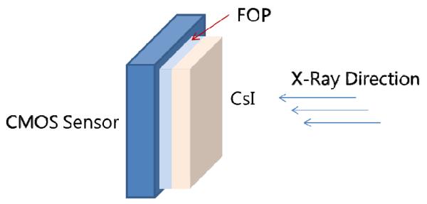
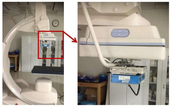
The 512 × 512 unbinned region of the CMOS detector was used for the image reconstruction. For this study, the detector was operated in low sensitivity mode. Figure 1 shows the schematic of the detector. This high resolution detector is mounted on a C-arm gantry with a state-of-the-art flat panel detector as shown in figure 2. The CMOS detector is attached to a special changer to enable it to be deployed in front of the standard flat panel detector when used and retracted to be parked within the C-arm when not being used.
Fig. 1.
Schematic of high resolution CMOS detector. A fiber-optic plate (FOP) interfaces the CsI(Tl) phosphor to the CMOS sensor.
Fig. 2.
C-arm gantry is shown with a high resolution CMOS detector mounted on a holder in front of the FPD (Shown by zoomed view within red box). The CMOS detector could be deployed or retracted using the motorized changer.
A commercial flat panel detector on the C-arm gantry was also used for the comparison. CBCT scans were taken with the two detectors of two neuro stents (Wingspan (Boston Scientific Neurovascular, Fremont, California) and Enterprise (Codman Neurovascular, Raynham, Massachusetts)) which were placed in a water-filled tube (fig 3) that was inserted in the center hole of a 16 cm CTDI PMMA phantom. The same matrix size, 512 × 512, was used for both detectors as shown in figure 4. The field of view of the FPD was 10 cm × 10 cm. while the FOV for the CMOS detector was 3.84 cm × 3.84 cm. For comparison, FPD data with its original pixel size of 194 microns and CMOS data with 75 microns was used for the reconstruction. The collimated field was set to the same size (10 cm × 10 cm in the detector plane) for both detectors to maintain the same scatter fraction. The technique parameters (80 kVp, 125 mA, 40 ms) chosen for the FPD by the imaging system were used for both detector assemblies. The anti-scatter grid on the FPD was removed and no grid was placed on the CMOS detector. The absence of an anti-scatter grid and the same technique parameters provide a fair detector comparison at the same dose to the detector; this results in the same patient dose, although the integral dose to the patient would be reduced with the CMOS detector due to its small field size (fig 4). For the input images to the reconstruction, we cropped 512 × 512 size images from both the detectors as shown in fig 4. The cropping of similar size image matrices with different pixel sizes provides different reconstruction volumes for the two detectors.
Fig. 3.
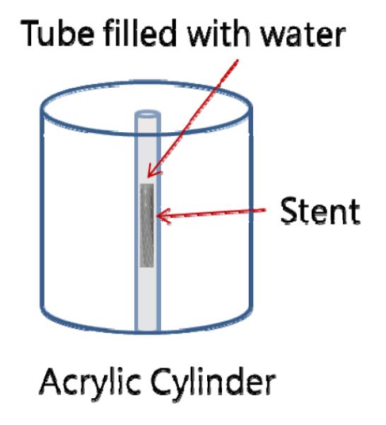
Schematic cylindrical phantom used for the study
Fig. 4.
The same 512 × 512 image matrix size was used for the FPD and the CMOS reconstruction as shown above.
For each detector, a total of 209 images were acquired using the rotational protocol with a 1 degree interval between images. The images were corrected for gain and offset, and used for the image reconstruction using a method based on the Feldkamp cone-beam reconstruction algorithm. The reconstructed images from both detectors were compared for image quality and spatial resolution. For the comparison of spatial resolution, 20 different struts cross sectional profiles were taken from the maximum intensity projection (MIP) images for both detectors and the averages of these 20 profiles were compared.
Results
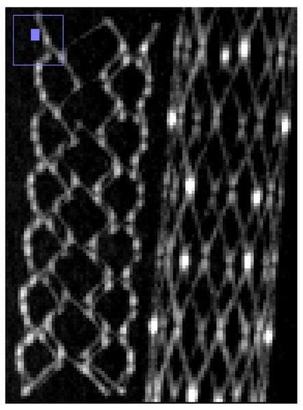
Comparison of reconstructed images of the cylindrical phantom with stents showed that the CMOS detector is capable of providing similar contrast and much improved spatial resolution capabilities. For the basic comparison, the same slice is shown for the two detectors in Fig. 5a and Fig. 5b. Visual comparison of images shown in fig 5 hints of the better spatial resolution with CMOS detector, where details of stent cross-sections are more clearly visualized - including instances where struts that are adjacent to one another are resolved only in the CMOS images. The strut thickness for the Enterprise stent is about 78 microns while that for the Wingspan stent is about 70 microns.
Fig. 5a.
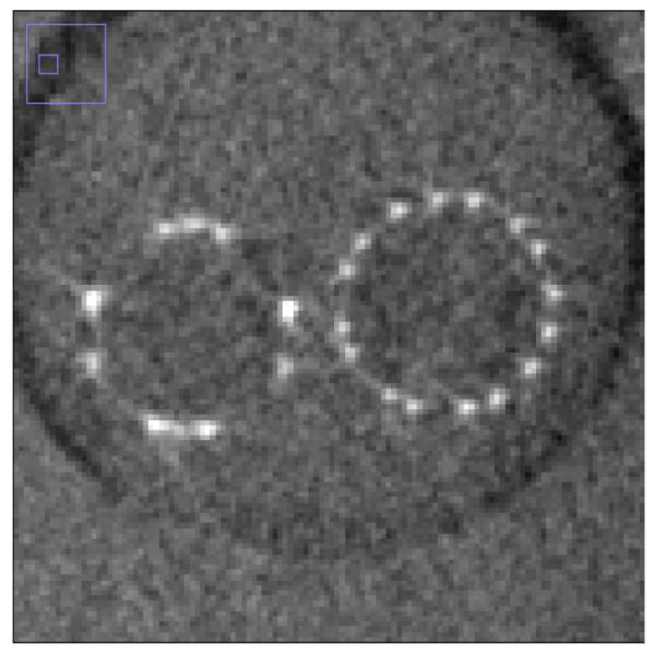
Stent phantom slice reconstructed with FPD images. (left: Enterprise stent, right: Wingspan stent
Fig. 5b.
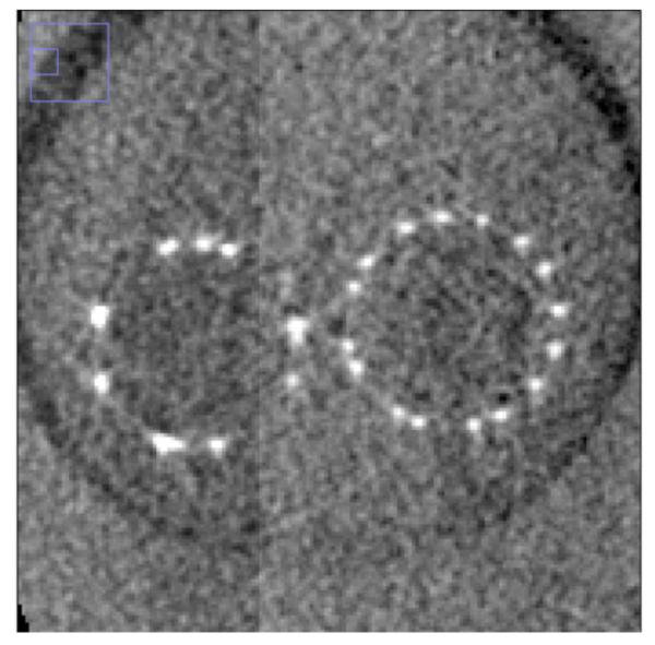
Stent phantom slice reconstructed with CMOS images. (left Enterprise stent, right: Wingspan stent) (Region shown with small blue box in left upper corner of each image shows the zoomed area of the image)
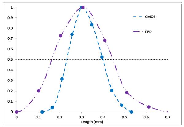
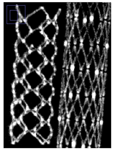
Fig. 6a and Fig. 6b shows the MIP images for the FPD and the CMOS. It is evident from these images that the use of the CMOS detector provides improved spatial resolution in comparison to the FPD. For the quantitative confirmation, 20 different line profiles of the struts of the Wingspan stent at the same location for both detectors are taken and aligned to get their average. These averages are plotted in figure 7. The FWHM for the average line profile for the FPD is about 300 microns while for the CMOS it is about 160 microns. This difference in the FWHM is also evident in the images. In figure 8, we have shown another MIP display of the reconstructed images. The stent on the right in fig. 8a and 8b has a different design in that the struts are not all connected. It is an open-cell design whereas the stent on the left appears as an Enterprise stent of the closed-cell kind. For the one on the right we can clearly see the gaps between the cells much better with the CMOS detector. While with the MIP display of the FPD images, it is hard to draw a conclusion about the stent cell structure.
Fig. 6a.
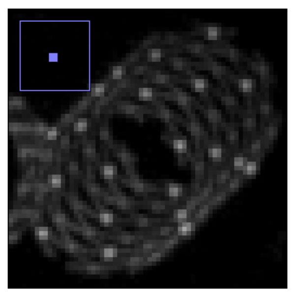
Maximum intensity projection image display of volume reconstructed images for the FPD
Fig. 6b.
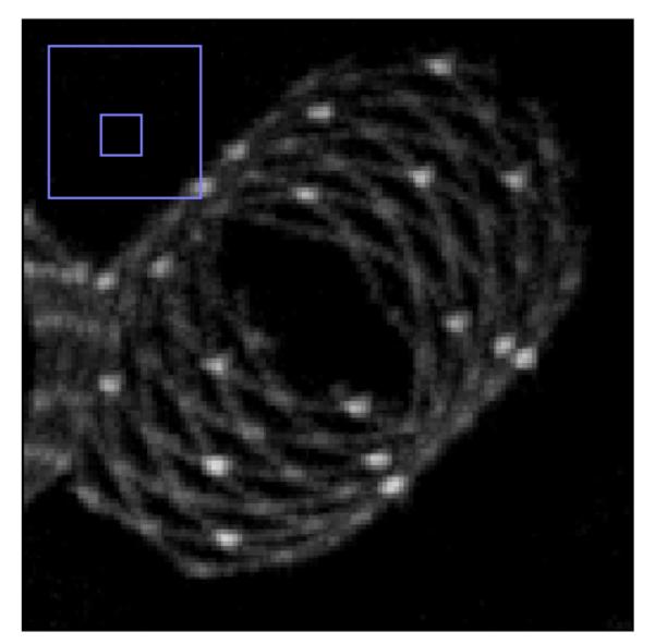
Maximum intensity projection image display of volume reconstructed images for the CMOS
Fig 7.
Comparison of line profiles of the stent struts in the MIP images obtained for the CMOS and the FPD shown above in figs. 6a and 6b.
Fig. 8a.
MIP display of reconstructed images from the FPD. (left: Enterprise stent, right: Wingspan stent)
Fig. 8b.
MIP display of reconstructed images from the CMOS. (left: Enterprise stent, right: Wingspan stent)
Conclusions
A high resolution CMOS detector was used as a ROI CBCT detector on a standard commercial angiography gantry to provide improved, high resolution 3D images. This CMOS detector can provide improved resolution 3D images with decreased integral patient dose if it is used with smaller field of view [13]. For this study, we were careful to avoid truncated data set but in real practice if we encounter with truncated data set, we could implement solution provided by others [10-11]. The full potential of a high resolution detector in x-ray imaging is not utilized fully due to the limitation and degrading effect of the finite size focal spot and geometric magnification. [14-15]. Use of a smaller focal spot will provide improvement in the overall imaging capability of the detector. For this work, even with the limitation imposed by the focal spot and magnification, the CMOS detector presents an improved image quality choice for x-ray and CBCT imaging. Thus further development of the concept and future clinical application are anticipated.
References
- 1.Bidaut LM, Laurent C, Piotin M, Gailloud P, Muster M. Second-generation three-dimensional reconstruction for rotational three-dimensional angiography. Acad. Radiol. 1998;5(12):836–849. doi: 10.1016/s1076-6332(98)80244-4. et. al. [DOI] [PubMed] [Google Scholar]
- 2.Fahrig R, Fox AJ, Lownie S, Holdworth DW. Use of a C-arm system to generate true three-dimensional computed rotational angiograms: preliminary in vitro and in vivo results. AJNR Am. J. Neuroradiol. 1997;18(8):1507–1514. [PMC free article] [PubMed] [Google Scholar]
- 3.Ning R, Kruger RA. Image intensifier-based computed tomography volume scanner for angiography. Acad. Radiol. 1996;3(4):344–350. doi: 10.1016/s1076-6332(96)80255-8. [DOI] [PubMed] [Google Scholar]
- 4.van Rooij WJ, Sprengers ME, de Gast AN, Peluso JPP, Sluzewski M. 3D rotational angiography: The new gold standard in the detection of additional intracranial aneurysms. AJNR Am. J. Neuroradiol. 2008;29(5):976–979. doi: 10.3174/ajnr.A0964. [DOI] [PMC free article] [PubMed] [Google Scholar]
- 5.Garcia JA, Chen J, Hansgen A, Wink O, Movassaghi B, Messenger JC. Rotational angiography (RA) and three-dimensional imaging (3-DRA): an available clinical tool. Int. J. Cardiovasc. Imaging. 2007;23(1):9–13. doi: 10.1007/s10554-006-9088-5. [DOI] [PubMed] [Google Scholar]
- 6.Ionita CN, Hoffmann KR, Bednarek DR, Chityala R, Rudin S. Cone-beam micro-CT system based on LabVIEW software. J. Digit Imaging. 2007;21(3):296–305. doi: 10.1007/s10278-007-9024-9. http://www.pubmedcentral.nih.gov/articlerender.fcgi?tool=pubmed&pubmedid=17333411. [DOI] [PMC free article] [PubMed] [Google Scholar]
- 7.Lee SC, Kim HK, Chun IK, Cho MH, Lee SY, Cho MH. A flat-panel detector based micro-CT system: performance evaluation for small-animal imaging. Phys. Med. Biol. 2003;48(24):4173–4185. doi: 10.1088/0031-9155/48/24/014. [DOI] [PubMed] [Google Scholar]
- 8.Song X, Frey EC, Tsui BMW. Development and evaluation of a MicroCT system for small animal imaging. IEEE Nuclear Science Symposium Conference Record.2001. pp. 1600–1604. [Google Scholar]
- 9. http://www.gehealthcare.com/usen/fun_img/pcimaging/products/rsmicroct.html.
- 10.Patel V, Hoffmann KR, Ionita CN, Keleshis C, Bednarek DR, Rudin S. Rotational micro-CT using a clinical C-arm angiography gantry. Med. Phys. 2008;35(10):4757–4764. doi: 10.1118/1.2989989. http://www.pubmedcentral.gov/articlerender.fcgi?artid=2663400. [DOI] [PMC free article] [PubMed] [Google Scholar]
- 11.Yu L, Zou Y, Sidky E, Pelizzari C, Munro P, Pan X. Region-of-interest reconstruction from truncated circular cone-beam data. IEEE Trans. Med. Imaging. 2006;25:869–881. doi: 10.1109/tmi.2006.872329. [DOI] [PubMed] [Google Scholar]
- 12.Jain A, Bednarek DR, Rudin S. Experimental and theoretical performance analysis for a CMOS-based high resolution image detector. Proc. SPIE. 2014:9033. doi: 10.1117/12.2043053. http://www.ncbi.nlm.nih.gov/pmc/articles/PMC4187383/ [DOI] [PMC free article] [PubMed] [Google Scholar]
- 13.Gill K, Ionita C, Bednarek D, Rudin S. Effective Dose Rate Comparison between the Micro Angiographic Fluoroscope (MAF) and the X Ray Image Intensifier (XII) Used during Neuro-Endovascular Device Deployment Procedures. Med Phys. 2011;38(6) [Google Scholar]
- 14.Jain A, Bednarek D, Rudin S. Evaluation of the microangiographic fluoroscope (MAF) using generalized system performance metrics. Med. Phys. 2013;40:031915. doi: 10.1118/1.4792460. http://www.ncbi.nlm.nih.gov/pmc/articles/PMC3598874/ [DOI] [PMC free article] [PubMed] [Google Scholar]
- 15.Jain A, Kuhls-Gilcrist AT, Gupta SK, Bednarek DR, Rudin S. Generalized two-dimensional (2D) linear system analysis metrics (GMTF, GDQE) for digital radiography systems including the effect of focal spot, magnification, scatter, and detector characteristics. Proc. SPIE. 2010;7622:1–10. doi: 10.1117/12.845293. 76220K. http://www.pubmedcentral.gov/articlerender.fcgi?artid=3021385. [DOI] [PMC free article] [PubMed] [Google Scholar]


