Abstract
A digital light projector is implemented as an integrated illumination source and scanning element in a confocal non-mydriatic retinal camera, the Digital Light Ophthalmoscope (DLO). To simulate scanning, a series of illumination lines are rapidly projected on the retina. The backscattered light is imaged onto a 2-dimensional rolling shutter CMOS sensor. By temporally and spatially overlapping the illumination lines with the rolling shutter, confocal imaging is achieved. This approach enables a low cost, flexible, and robust design with a small footprint. The 3rd generation DLO technical design is presented, using a DLP LightCrafter 4500 and USB3.0 CMOS sensor. Specific improvements over previous work include the use of yellow illumination, filtered from the broad green LED spectrum, to obtain strong blood absorption and high contrast images while reducing pupil constriction and patient discomfort.
Keywords: Digital Light Ophthalmoscope, LightCrafter, rolling shutter, DLP, CMOS, imaging, retina, confocal imaging
1. INTRODUCTION
Confocal imaging is a well-known imaging technique in which light returning from a target is spatially filtered prior to detection. Spatial filtering is commonly used to reduce image artifacts, improve image contrast, and isolate features of interest, which has helped popularize it for biomedical imaging applications.
Laser scanning confocal imaging systems traditionally illuminate a target with a point or line that is rapidly scanned across the field of view. The light returning from the target is descanned and directed through an aperture to a photosensitive detector. By synchronizing the scanning with the exposure timing of the detector, a two-dimensional image of the target is constructed. Adjustments to the aperture position, shape, and size allow a user to trade off the amount of spatial filtering with the amount of light returning from the target that is detected.
An alternate approach to laser scanning confocal imaging makes use of the rolling shutter method of detection that is common to complementary metal oxide semiconductor (CMOS) sensor chips1-3. Unlike a global shutter, which integrates charge evenly across the entire active sensor area during the exposure time, the rolling shutter integrates light over one or more pixel rows at a time, spanning a “shutter width.” During each frame, the rolling shutter progressively scans across the active sensor region with a shutter width equal to the exposure time divided by the horizontal line read time3. Light incident on the sensor outside the active rolling shutter read area is not captured, and therefore cannot reduce contrast.
The rolling shutter means of detection has historically been criticized for its performance when imaging moving targets and using short exposure times, which can cause wobble, skew, smear, and partial exposure. However, these detection characteristics can also be used to one’s advantage, for example, in pose recovery motion algorithms4 and line-scanning confocal retinal imaging5, 6. To perform confocal imaging with the rolling shutter, a target is illuminated with a line that is scanned across the field of view. Rather than descanning the light returning from the target, it is imaged directly onto a 2D CMOS pixel array. The position of the line focused on the target is matched to the position of the rolling shutter throughout the frame exposure. With spatial filtering provided by a narrow shutter width, directly backscattered light is preferentially detected, while out-of-focus and multiply scattered light is rejected.
A benefit of confocal imaging using the rolling shutter is that it allows adjustments to the shutter position and width in pixel increments on a frame-to-frame basis. Compared with mechanical apertures, the rolling shutter allows much more precise and rapid changes to the spatial filter function since it is electronically controlled in real-time.
The Laser Scanning Digital Camera (LSDC) is a line-scanning camera that uses the rolling shutter to obtain confocal images of the retina for cost-effective diabetic retinopathy screening and visual function measurements7-9. By offsetting the rolling shutter position with respect to the illumination line, the imaging system can rapidly switch to a dark-field imaging mode, which has been used to detect scattering defects in the deeper retina that are normally masked by scattering in the superficial retina10.
The rolling shutter spatial filter has also been demonstrated as an optical frequency filter when a dispersive element is added to the detection pathway. In this case, the rolling shutter is matched to a particular wavelength of light returning from the target. The shutter width controls the spectral bandwidth that is detected while its starting position adjusts the center wavelength. When applied to fluorescence imaging, the spectral components of the fluorescent emission from the target can be selectively isolated and imaged11.
To perform confocal imaging, the LSDC requires a laser illumination source and galvanometer scanning element to deliver light onto the retina. The present technique has been developed in which the source and scanning element required in laser scanning confocal systems are substituted for a digital light projector (DLP)12,13. The DLP uses a choice of high power red, green, and blue light emitting diodes (LEDs) to illuminate a digital micromirror array that is located at a conjugate target plane. To simulate line-scanning, the DLP is programmed to rapidly project a series of narrow adjacent lines, which are matched to the position of the sensor’s rolling shutter during a frame exposure. Confocal imaging using a DLP illumination source has been demonstrated for retinal imaging, dual-wavelength and fluorescence imaging, and for Fourier domain optical coherence tomography13-17.
The combination of the spatial light modulation of a DLP with the spatial filtering provided by the rolling shutter of a CMOS sensor permits a cost effective and compact implementation of a confocal imaging system. The fact that the DLP can be used as a source without hardware modification and can be driven directly from software reduces electronic complexity while allowing for more versatile illumination geometries than that provided by a pair of scanning mirrors.
In this work, the third generation of the Digital Light Ophthalmoscope (DLO) retinal camera is presented, shown in Figure 1. Improvements over the previous generation design18 include the use of a newer DLP (DLP LightCrafter 4500, Texas Instruments Inc., Dallas, TX) which provides greater illumination power and improved timing synchronization. The additional illumination power allows for retinal imaging using yellow light that is filtered from the broad green LED spectrum. Combined with a new USB3.0 CMOS camera (UI-3480CP-M, IDS Imaging Development Systems GmbH, Obersulm, Germany) that uses the same Aptina 5MP MT9P031 sensor chip, and an improved optical design that better rejects wanted corneal reflections, the third generation DLO performs real-time non-mydriatic retinal imaging at a maximum frame rate of 41 Hz with a 38 deg. retinal field of view.
Figure 1.
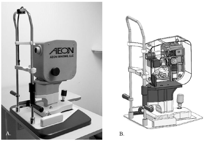
A: The 3rd generation Digital Light Ophthalmoscope (DLO). B: The DLO enclosure, built with a 3D printer, uses press-fit grooves for simple and fast optical component placement. Fine alignment of the illumination field of view and sensor region of interest is performed through software.
The illumination wavelength for retinal imaging is typically chosen depending on source availability, cost, available power, and imaging application19. For high contrast visualization of the superficial retina, visible green wavelength light (near 530 nm) is often used in fundus cameras due to its strong hemoglobin and oxygenated hemoglobin absorption, shown in Figure 220. Unfortunately, illumination at these wavelengths with relatively low average powers cause pupil constriction, increased melanin absorption, and patient discomfort. These side effects are all detrimental to the task of obtaining a high proportion of gradable non-mydriatic images among a diverse population for applications such as diabetic retinopathy screening.
Figure 2.
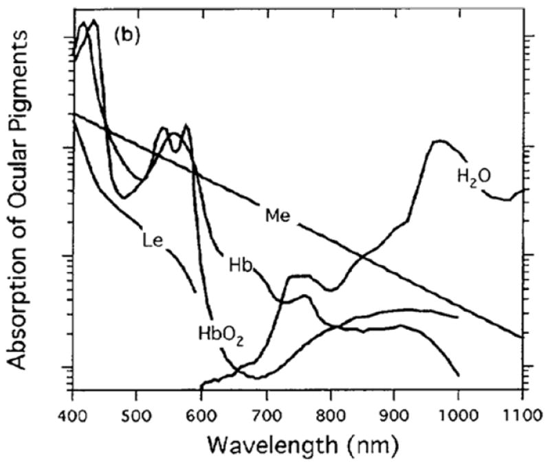
Ocular pigment absorption measured through the visible and near infrared wavelength range measured with a scanning laser ophthalmoscope by Elsner et. al. in 199620. Imaging of the superficial retina, with high contrast visualization of the vasculature is frequently done with green wavelength sources, though strong hemoglobin (Hb) and oxygenated hemoglobin (HbO2) absorption exists at slightly longer wavelengths in the yellow and orange (560-590 nm).
As shown by Elsner et. al.20, the absorption of hemoglobin and oxygenated hemoglobin peaks near 560 nm and starts to rapidly decrease thereafter. Although the use of an illumination wavelength between 560 nm and 600 nm still provides strong blood absorption, and would largely mitigate the unwanted side-effects of using wavelengths shorter than 560 nm, the availability of laser sources in this wavelength range remains cost-prohibitive. A key benefit of the 3rd generation DLO is the ability to long pass filter the broadband green illumination LED and maintain sufficient power for retinal imaging with 560-600 nm yellow light.
2. METHODOLOGY
The third generation DLO uses the DLP LightCrafter 4500 released in 201321, which has a 912×1140 digital micromirror resolution and a 3 channel 8-bit red, green, and blue LED output. As in previous DLO implementations, the DLP is operated in its structured light mode in order to project a series of adjacent rectangular lines in rapid progression that are timed and spatially located according to the position of the CMOS rolling shutter. In this configuration, a series of 48 monochrome illumination lines are pre-loaded into an internal memory buffer and displayed with a maximum pattern projection rate of 4.225 kHz. Unlike the 2nd generation DLO, the DLP is run as the master, sending a start-of-frame trigger signal to the CMOS camera after every 48 displayed patterns.
A comparison power measurement between the DLP LightCrafter and DLP LightCrafter 4500 was made when projecting a solid green internal test pattern at the maximum LED current. The light output from the projector was collected and refocused to a power meter head. A reflective ND1.0 filter (ND10A, Thorlabs Inc., Newton, NJ) reduced the light output to stay within the measurement range of a PM100D power meter with an S120C power meter head (Thorlabs Inc., Newton, NJ). Unlike the LightCrafter 4500, the LightCrafter does not include active fan cooling of the LED heatsinks, which results in decreasing power output over minutes of use when the LED is driven at its maximum current. The LED current was therefore switched from minimum to maximum for only the several seconds required to perform a power measurement. The green LED was found to have approximately 2.5 times greater power output on the LightCrafter 4500.
The spectrum of the LightCrafter 4500’s white-light output, shown in Figure 3, was measured with a USB4000-VIS-NIR spectrometer (Ocean Optics, Inc., Dunedin, FL, USA). The three peaks show, from left to right, the spectrum from the blue, green and red LED channels, respectively. The blue LED channel is not used for retinal imaging due to ocular safety considerations and patient comfort. Figure 4 shows a section of the green LED spectrum, measured after inserting a 570 nm long pass filter (46-061, Edmund Optics Inc., Barrington, NJ). The long pass filter rejects approximately 86% of the green LED power output, allowing just the tail end of the spectrum to reach the eye.
Figure 3.
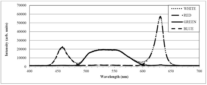
Optical spectrum of Texas Instruments’ DLP LightCrafter 4500. The three peaks show, from left to right, the output of the blue, green, and red LED channels, respectively.
Figure 4.
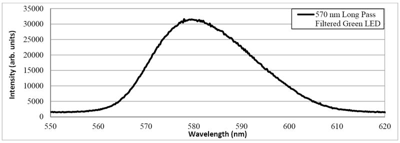
Optical spectrum of the DLP LightCrafter 4500’s green LED illumination after 570 nm long pass filtering. Sufficient optical power remains in the tail of the green LED spectrum to perform retinal imaging with a center wavelength of approximately 580 nm.
The 5 megapixel monochrome CMOS sensor used by the IDS camera was set to operate with a region of interest of 1920×1920 pixels, with 2x binning. Unlike the 2nd generation DLO, the timing synchronization was performed with the DLP LightCrafter 4500 acting as the master. The LightCrafter 4500 was configured to output a trigger pulse every 48 patterns, thus removing the need for additional timing electronics. Although the individual line patterns were no longer triggered by a factor of the sensor row read-out, the temporal stability of the line patterns and rolling shutter was sufficient to maintain temporal synchronization through-out the frame exposure. The 3rd generation DLO used half the number of line patterns as compared to its predecessor, resulting in wider illumination lines at the retina and reducing the ability to spatially filter the light return from the retina. This trade-off was required to make use of the additional light output from the LightCrafter 4500 for pupil separation and for filtering the green LED to obtain yellow illumination.
The use of the LightCrafter 4500 and rolling shutter method of detection enables a simple free-space optical design for retinal imaging, as shown in Figures 5 and 6. The illumination pathway, shown in Figure 5, collimates, polarizes and long pass filters the projected light from the DLP. The illumination is relayed by a pair of 60 mm achromat lenses to a conjugate pupil plane where it is spatially filtered by an iris that is offset from the optical axis. The spatial filtering allows fine control over pupil separation, and permits average illumination power at the cornea to be traded off with illumination pupil size. Since the system is telecentric, the offset iris uniformly reduces the intensity of the illumination seen at the conjugate retinal imaging plane. The spatially filtered light passes through a polarizing beamsplitter. For simplicity, the polarizing beamsplitter is shown in Figure 5 to transmit approximately all of the polarized illumination light towards the eye. In the 3D printed DLO, the polarizing beamsplitter reflects the illumination light toward the eye, which permits a smaller overall footprint, and a center of mass that is not offset from its alignment base. The light is relayed by a 100 mm achromat lens to an ocular lens pair with an effective focal length of 35 mm, where it is then focused into the eye. Refractive error correction is achieved by adjusting the distance between lenses L3 and L4.
Figure 5.

Optical diagram of the Digital Light Ophthalmoscope (DLO) illumination pathway. Light projected by the DLP LightCrafter 4500 (left) is projected through a series of optics to the eye (right). The light is polarized with polarizer P1, and long-pass filtered at 570nm with F1. Lenses L1 and L2 relay the illumination to a conjugate pupil plane, where an iris is offset from the optical axis. The iris diameter is directly proportional to the pupil diameter, and is set for 20-30 μW of average power is at the cornea with yellow illumination. The edge of the iris is positioned at the optical axis. The polarizer is set so that the light transmitted by the polarizing beamsplitter PBS is maximized. Lenses L3 and L4 relay the illumination to the eye, where it is focused through the pupil to the retina. Focus adjustment is achieved by adjusting the distance between lenses L3 and L4.
Figure 6.

Optical diagram of the Digital Light Ophthalmoscope (DLO) detection pathway. Cross-polarized light return from the retina (left) passes through lenses L4 and L3 and is reflected by the polarizing beamsplitter PBS to the CMOS camera. The camera and camera lens are positioned so that the camera lens stop is located at a conjugate pupil plane. The camera and camera lens are offset from the optical axis, with the iris stop diameter adjusted so that it removes reflections at and close to the pupil plane. A small offset from the optical axis (one quarter the conjugate pupil size) is used to minimize optical aberrations.
The light return pathway from the retina to the camera is shown in Figure 6. Cross-polarized light return is reflected by the polarizing beamsplitter to the detection pathway, where is it focused by a 16 mm focal length compound camera lens through an adjustable iris (MVL16M23, Thorlabs Inc., Newton NJ) to the IDS camera. The camera lens is positioned so that the internal iris is located at the conjugate pupil plane. The camera and camera lens are then slightly offset from the optical axis in the opposite direction to the illumination pupil. By adjusting the illumination and detector irises, reflections from the pupil plane can be removed while maintaining a full retinal imaging field of view. Cross-polarized light detection is performed to remove unwanted reflections from the optical elements placed between the polarizing beamsplitter and the eye. The focus of the LightCrafter 4500 and camera lens are both set to a target placed in the conjugate retinal plane. Temporal synchronization between the rolling shutter and illumination lines is achieved by adjusting the camera’s trigger delay. Fine adjustments to the spatial synchronization are achieved by reloading spatially shifted illumination line patterns or, when the sensor region of interest permits, the starting pixel row of the frame exposure.
The integration of the light sources, driver, and spatial light modulator into a single DLP package reduces the cost and time required to align a separate light source and galvanometer scanner, and interface it to the rest of the imaging system. By adjusting the starting row and column of the illumination and detection regions of interest, small adjustments to the optical alignment may be made through software without the need for kinematic mounts or time-consuming manual alignment. The DLO components are enclosed in a pair of plastic mounts that were custom designed and built by a 3rd party vendor (Quickparts.com Inc., Atlanta, GA). The DLO enclosure not only eliminates stray light and keeps the components protected from the environment, but also holds the optics in set locations according to the optical design. The 3rd generation DLO occupies a footprint of approximately 10”×6.7”×10” and weighs approximately 5 lbs.
The DLO is attached to a standard slit-lamp base for retinal imaging, shown in Figure 7. The retina is illuminated using the DLP’s built-in red (centered at 630 nm) or yellow filtered-green (centered at 580 nm) LED channels. A small, adjustable, input-output pupil of approximately 2-3 mm permits non-mydriatic imaging in patients with small pupils. Acquired red and yellow image frames overlaid to present the operator with a real-time pseudo color fundus image with a digital resolution of 960 × 960 pixels. Image acquisition is performed on an Intel Core i7 laptop (Asus Q550LF) running Windows 8 through a custom-built user interface. Monochrome retinal images were acquired with 12 bit-depth resolution. The green and red LEDs were alternately enabled and disabled every frame. Image frames were dark-background subtracted and auto-intensity scaled before being combined into a pseudo-color image OpenGL for display.
Figure 7.
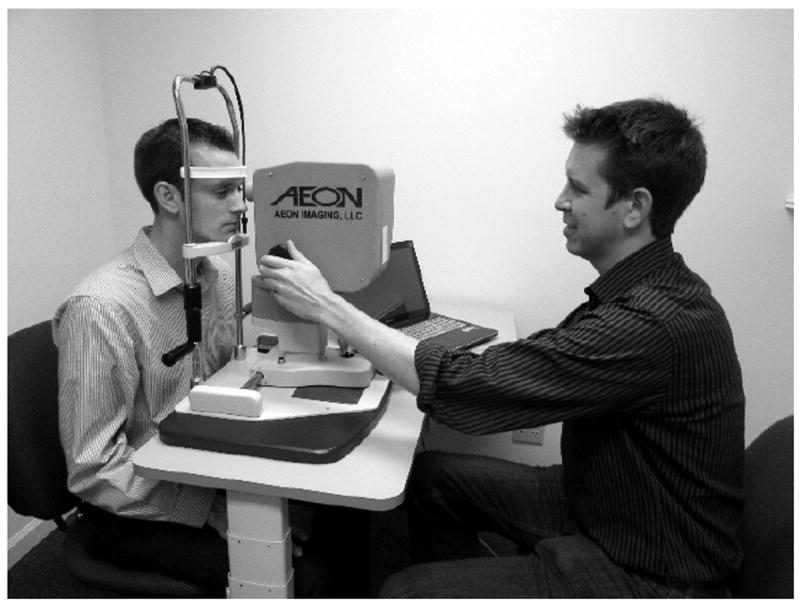
The Digital Light Ophthalmoscope (DLO), mounted on a slit-lamp alignment base for retinal imaging.
In addition to the sequence of lines, the DLP also projects an X used to guide the subject’s fixation. The subject perceives this brighter fixation pattern over a red light background. The X is projected when the rolling shutter is displaced laterally in the retinal field, which excludes the backscattered fixation light from appearing in the retinal image. Typically, the illumination pupil iris diameter was decreased until an average power between 20 μW and 30 μW was obtained at the cornea for both the red and yellow-filtered green channels. With additional image registration, filtering and averaging, retinal images have been obtained on undilated subjects with as little as 5 μW time-averaged power per channel. At an average power of 20 – 30 μW, the illumination is comfortable for subjects, the combined illumination and detection pupils have a diameter less than 3 mm and very minimal pupil constriction occurs. With a line-illumination geometry, the time-averaged powers are well-within ANSI safe exposure limits.
By switching to the IDS camera, the 3rd generation design obtains three specific advantages. First, the USB3.0 camera interface is readily compatible with new desktop and laptop hardware and Windows software, while achieving similar pixel transfer rates to the 2nd generation sensor’s parallel bit read-out, which required a Linux-based driver. Second, the IDS camera allows adjustments to the external trigger delay, which permits users to set a temporal offset between the rolling shutter and projected line illumination for multiply scattered light imaging. In previous designs, synchronization offsets for scattered light imaging were achieved spatially by adjusting the sensor’s pixel region of interest. Adjustment to the starting pixel row usually causes a dropped frame, which limits the frame rate that can be achieved when acquiring alternating bright- and dark-field images in real-time. Further, adjustment to the starting row had the undesired effect of spatially shifting the field of view. Third, the IDS camera software permits adjustments to the pixel clock in MHz increments. Combined with a variable DLP pattern exposure time, the 3rd generation DLO allows users to actively tradeoff imaging frame rate for increased light exposure time, while maintaining a constant confocal shutter width. In the present design, the pattern time was increased from 385 μsec to 1.45 msec, reducing the frame rate to 14.3 Hz. The maximum frame rate is limited by the speed of the sensor, equal to 41 Hz at a 1920×1920 pixel resolution with 2X binning.
The DLO illumination line width of 20 pixels at the sensor after 2x binning is limited by the pattern storage of the LightCrafter 4500 (only 48 patterns can be pre-loaded without incurring additional timing overhead), and the desired sensor frame rate and imaging pixel resolution. A sensor exposure time of 3.5 msec was used, corresponding to a rolling shutter width of approximately 75 binned pixel rows, which provides a good trade-off between the amounts of spatial filtering (perceived by retinal vessel contrast) and light detected. With the illumination line width roughly equal to one-quarter the rolling shutter width, the projected lines closely approximate a continuous line scanning system.
3. RESULTS
A sample 50-frame averaged pseudo color retinal image of an undilated 64 year old female Caucasian subject is shown in Figure 8A. Its composite red and green color channel images were taken with red (630 nm) and yellow (580 nm) illumination with an average power at the cornea of 25 μW. Due to the DLO’s polarization sensitive detection and the birefringence present in Henle’s fiber layer, a circular intensity variation in the macula, called the macular cross, is visible in images of the healthy retina (shown with arrow in Figures 8C and 9A). Accurate localization of the fovea can be helpful, particularly with respect to the location of retinal lesions when diagnosing treatment for retinal disease, or for assessing central visual function. The macular cross can also provide a useful landmark for adaptive optics imaging systems, which acquire high magnification retinal images over small (2-3 deg) fields of view at a specific retinal location of interest that is determined a priori.
Figure 8.

50-frame averaged DLO image of an undilated 64 year old normal Caucasian female imaged at the Indiana University School of Optometry. A: Pseudo color retinal image. B: Red channel image, acquired with red illumination (630 nm). C: Green channel image, acquired with yellow illumination (580 nm). The macular bow tie (shown with arrow), caused by the birefringence in Henle’s fiber layer, can help locate the fovea. Accurate foveal localization can be important for the diagnosis of vision threatening disease, as well as for repositioning small field of view devices, such as adaptive optics imaging systems.
Figure 9.
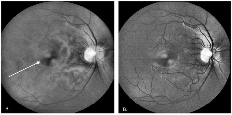
50-frame averaged DLO image of an undilated 28 year old normal Asian male imaged at the Indiana University School of Optometry. A: Red channel image, acquired with red illumination (630 nm). White arrow shows the macular bow tie pattern caused by the birefringence in Henle’s fiber layer. B: Green channel image, acquired with yellow illumination (580 nm). The red illumination penetrates the deeper retina, providing visualization of the choroidal vasculature, whereas the yellow illumination has higher blood vessel contrast and provides better visualization of the superficial retina and nerve fiber layer.
The sample image shown in Figure 8A is comprised of two 50-frame buffers that were acquired using alternating red and yellow-filtered green LED illumination. The frames were registered to account for eye motion and averaged in post-processing. The images were further filtered to remove fixed pattern noise from the DLP, and their intensity was nonlinearly scaled to avoid image saturation around the optic disc. The averaged images were then overlaid to create a color representation of the retina that is familiar to eye care professionals. By alternating the illumination every frame, pseudo color image frame pairs contain little retinal motion, which simplifies the post-processing registration steps and maintains accurate pseudo coloring of the retina. The use of these alternating operating modes slows the frame rate to 7.2 Hz (per pair of image frames), which makes the imaging more susceptible to motion artifacts in patients with poor fixation stability. However, frames with excessive eye motion or image shearing can be removed in post-processing, and the pixel clock rate and pattern exposure rate on the 3rd generation DLO can both be increased to perform imaging at higher rates (up to 20.5 Hz per pair of image frames).
Although many eye care providers prefer color fundus photos, separate review of the red and green illumination DLO images can provide diagnostically useful information. Consistent with Elsner17, red illumination penetrates the deeper retina, providing visualization of the choroidal vasculature and detection of scattering defects in the retinal pigment epithelium, while green illumination provides a view of the superficial retina, with strong vessel contrast due to blood absorption. An example red and green image pair of a 28 year old Asian male is shown in Figure 9A and 9B, which illustrates the imaging differences resulting from illumination wavelength.
The 3rd generation DLO was found to resolve its most significant previously reported limitations. The Texas Instruments DLP LightCrafter 4500, as opposed to the DLO’s previously used Texas Instruments DLP LightCrafter (2nd generation) and DLP v2.0 Software Development Kit (1st generation), provides brighter LEDs, enabling power trade-offs for filtering the green LED illumination to 580 nm yellow light, and for improved pupil separation to remove corneal reflections, particularly in patients with small pupils. Furthermore, the 3rd generation DLO is able to obtain high quality images with less than half the light levels used by the 2nd generation system, due to the acquisition of all 12 bits from the camera, reduced dark levels, increased pattern and sensor exposure time, and real-time auto-intensity scaling post-processing. The 3rd generation DLO illumination is no longer excessively bright to patients and minimizes pupil constriction, due to the lower average power levels, and the use of yellow, rather than green illumination. One drawback with the new generation system is the use of wider lines on the retina, which reduces the amount of spatial filtering of undesired scattered light by the rolling shutter. However, the visibility of fine, third- and fourth-order vessel branches indicates that the imaging performance has been maintained despite using a slightly wider confocal rolling shutter.
4. CONCLUSIONS
The DLP LightCrafter 4500 has been implemented in a 3rd generation DLO to perform cost-effective non-mydriatic retinal imaging. By rapidly projecting a series of rectangular lines onto a target, the DLP simulates line-scanning. The lines are temporally and spatially overlapped with the rolling shutter of a 2D CMOS sensor, which spatially filters the light returning from the target. The DLP can be adjusted in real-time for green or red illumination imaging, as well as for bright and dark field imaging. As expected, imaging with red illumination causes less pupillary constriction, displays greater retinal scattering, and provides deeper penetration for visualization of the choroidal vessels and defects in the retinal pigment epithelium layer. The yellow-filtered green illumination provides higher vessel contrast due to blood absorption and better visualization of the superficial retina and nerve fiber than the red illumination, while reducing pupil constriction and patient discomfort as compared to shorter wavelength green illumination. Images obtained using commercially available flood illumination and confocal scanning laser cameras show comparable levels of fine retinal vessel detail.
The use of the 3 channel LEDs and micromirror array integrated in the DLP provide several advantages over existing confocal laser scanning technology. Handheld DLPs are compact, robust, and cost-effective, making them strong candidates for use in portable devices outside of controlled clinical and research environments. They are controlled by software, which permits real-time adjustments to the output pattern in response to image feedback, or depending on the imaging modality desired. Finally, their implementation with rolling shutter CMOS sensors avoids descanning and any associated hardware modifications, permitting relatively simple integration into an imaging system. The 3rd generation DLO’s use of an IDS camera permits adjustments to the trigger delay to control the temporal synchronization, and adjustments to the pixel clock frequency. When combined with the pattern exposure time, the DLO can increase its sensitivity in exchange for a lower frame rate, while maintaining the same amount of confocal rejection of scattered light.
The use of a spatial light modulator to simulate line scanning in confocal imaging with rolling shutter detection permits large reductions in imaging system size, cost, and complexity for a range of imaging applications, while the key hardware limitations have solutions that are well-aligned with the goals of DLP commercial development for consumer presentation devices, and the goals of CMOS sensor development for cost-effective cameras in consumer tablets, webcams, and smart phones. The benefit of the CMOS rolling shutter used when progressively scanned is demonstrated.
References
- 1.Key differences between rolling shutter and frame (global) shutter. Point Grey Research, Inc.; [1/19/2015]. Knowledge Base. http://www.ptgrey.com/support/kb/index.asp?a=4&q=115. [Google Scholar]
- 2.Introduction to CMOS Image Sensors. Olympus America; [1/19/2015]. http://www.olympusmicro.com/primer/digitalimaging/cmosimagesensors.html. [Google Scholar]
- 3.Shutter Methods. [1/19/2015];IDS Imaging Development Systems GmbH, uEye manual 4.60. https://en.ids-imaging.com/manuals/uEye_SDK/EN/uEye_Manual/index.html.
- 4.Ait-Aider O, Andreff N, Lavest JM, Martinet P. Simultaneous Object Pose and Velocity Computation Using a Single View from a Rolling Shutter Camera. ECCV 2006. 2006;3952:56–68. Part II, LNCS. [Google Scholar]
- 5.Zhao Y, Elsner AE, Haggerty BP, et al. Confocal Laser Scanning Digital Camera for Retinal Imaging. Invest Ophthal Vis Sci. 2007;48:4265. [Google Scholar]
- 6.Elsner AE, Petrig BL. Laser Scanning Digital Camera with Simplified Optics and Potential for Multiply Scattered Light Imaging. #7,831,106. US Patent. 2007
- 7.Muller MS, Elsner AE, VanNasdale DA, et al. Low Cost Retinal Imaging for Diabetic Retinopathy Screening. Invest Ophthal Vis Sci. 2009;50:3305. [Google Scholar]
- 8.Ozawa GY, Litvin T, Cuadros JA, et al. Comparison of Flood Illumination to Line Scanning Laser Opthalmoscope Images for Low Cost Diabetic Retinopathy Screening. Invest Ophthal Vis Sci. 2011;52:1041. [Google Scholar]
- 9.Petrig BL, Muller MS, Papay JA, Elsner AE. Fixation Stability Measurements Using the Laser Scanning Digital Camera. Invest Ophthal Vis Sci. 2010;51:2275. [Google Scholar]
- 10.Muller MS, Elsner AE, VanNasdale DA, Petrig BL. Multiply Scattered Light Imaging for Low Cost and Flexible Detection of Subretinal Pathology. OSA Tech Digest. 2009 FiO FME5. [Google Scholar]
- 11.Muller MS, Elsner AE, Petrig BL. Inexpensive and Flexible Slit-Scanning Confocal Imaging Using a Rolling Electronic Aperture. OSA Tech Digest. 2008 FiO FWW2. [Google Scholar]
- 12.Muller MS. Confocal Imaging Device Using Spatially Modulated Illumination with Electronic Rolling Shutter Detection. No. 8,237,835. US Patent. Issued August 7, 2012.
- 13.Muller MS. A Pico Projector Source for Confocal Fluorescence and Ophthalmic Imaging. Proc SPIE. 2012;8254 doi: 10.1117/12.909574. [DOI] [PMC free article] [PubMed] [Google Scholar]
- 14.Muller MS, Elsner AE, VanNasdale DA. Low-cost Confocal Retinal Imaging with a Digital Light Projector Source. Invest Ophthal Vis Sci. 2012;53:3099. [Google Scholar]
- 15.Elsner AE, Muller MS, Petrig BL, et al. Low-cost digital light projector camera for screening applications. UC Berkeley BCSDP Annual Conference; 2012. [Google Scholar]
- 16.Elsner AE, Young S, McIntyre C, et al. Scattered Light Imaging with Patterned Illumination. Am Acad Opt. 2012 120434. [Google Scholar]
- 17.Litvin TV, Ozawa GY, Cuadros JA, et al. Evaluation of the Digital Light Projector Camera (DLP-Cam) for Low-Cost Diabetic Retinopathy Screening. Invest Ophthal Vis Sci. 2013;54:5844. [Google Scholar]
- 18.Muller MS, Elsner AE, Ozawa GY. Non-Mydriatic Confocal Retinal Imaging Using a Digital Light Projector. Proc SPIE. 2013;85670Y doi: 10.1117/12.2001305. [DOI] [PMC free article] [PubMed] [Google Scholar]
- 19.Elsner AE, Muller MS. Laser applications and system considerations in ocular imaging. Laser Photonics Review. 2008;2(5):350–376. doi: 10.1002/lpor.200810015. [DOI] [PMC free article] [PubMed] [Google Scholar]
- 20.Elsner AE, Burns SA, Weiter JJ, Delori FC. Infrared Imaging of Sub-retinal Structures in the Human Ocular Fundus. Vision Research. 1996;36(1):191–205. doi: 10.1016/0042-6989(95)00100-e. [DOI] [PubMed] [Google Scholar]
- 21.DLP LightCrafter 4500 Evaluation Module User’s Guide. Texas Instruments Inc.; Jan 18, 2015. Literature Number DLPU011D, July 2013, Rev. June 2014 < http://www.ti.com/lit/ug/dlpu011d/dlpu011d.pdf>. [Google Scholar]


