Abstract
Photoinduced bond cleavage is often employed for the generation of highly reactive carbocations in solution and to study their reactivity. Diphenylmethyl derivatives are prominent precursors in polar and moderately polar solvents like acetonitrile or dichloromethane. Depending on the leaving group, the photoinduced bond cleavage occurs on a femtosecond to picosecond time scale and typically leads to two distinguishable products, the desired diphenylmethyl cations (Ph2CH+) and as competing by-product the diphenylmethyl radicals (). Conical intersections are the chief suspects for such ultrafast branching processes. We show for two typical examples, the neutral diphenylmethylchloride (Ph2CH–Cl) and the charged diphenylmethyltriphenylphosphonium ions () that the role of the conical intersections depends not only on the molecular features but also on the interplay with the environment. It turns out to differ significantly for both precursors. Our analysis is based on quantum chemical and quantum dynamical calculations. For comparison, we use ultrafast transient absorption measurements. In case of Ph2CH–Cl, we can directly connect the observed signals to two early three-state and two-state conical intersections, both close to the Franck-Condon region. In case of the , dynamic solvent effects are needed to activate a two-state conical intersection at larger distances along the reaction coordinate.
I. INTRODUCTION
Photoinduced bond cleavage constitutes a common way to generate highly reactive species like carbocations in situ.1–6 In particular, in the case of diarylmethyl (Ar2CH) compounds, the in situ generated carbocations are used to study their reactions with nucleophiles.6,7 Ph2CH+ and its various derivatives serve as reference electrophiles for one of the most extensive reactivity scales covering 40 orders of magnitude which is being developed by Mayr and coworkers.7–10 Different leaving groups (LGs) are used depending on the conditions under which the reactive species are generated.4–6 In the case of polar solvents like acetonitrile, Ph2CH–Cl is a suitable precursor. But for less polar solvents like dichloromethane or chloroform, the Ph2CH+ cation yield is extremely small on the nanosecond time scale.5,6 Using these solvents, constitutes a much better precursor for the Ph2CH+ generation.4,6 From a chemists point of view, this seems to be reasonable as the LG carries already a positive charge, and thus the generation of cations should be electrostatically preferred because no charge separation is necessary during bond cleavage.
Ultrafast broadband transient absorption measurements show that the Ph2CH+ generation differs for both LGs. In the case of Cl, initially homolytic bond cleavage occurs on the hundreds of femtoseconds time scale followed by an electron transfer, which finally results in the ion pairs Ph2CH+ + Cl−.5 The smaller driving force of the electron transfer in less polar solvents is the reason why the Cl LG is not suited for moderately polar solvents. In the case of , the measurements reveal a direct formation of Ph2CH+ for polar as well as moderately polar solvents.4 These observations already indicate that the underlying bond cleavage mechanisms might be different.
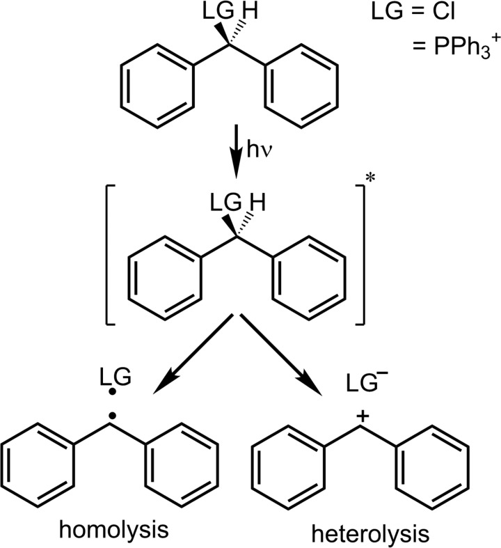
In the present work, we theoretically investigate the photoinduced bond cleavage of Ph2CH–Cl and (see Fig. 1) by means of state-of-the-art quantum chemical and quantum dynamical methods. We will discuss the individual molecular features introduced by the LG including two- and three-state conical intersections (CoIns) optimized at the complete active space self consistent field (CASSCF) level of theory. Three-state CoIns have already been shown to be important for photochemistry.11–13 To perform quantum dynamics (QD), we calculated potential energy surfaces (PESs) for both precursors in reduced dimensionality at the “our own n-layered integrated molecular orbital and molecular mechanics” (ONIOM) level of theory.14–17 In the case of Ph2CH–Cl, the PESs have been diabatized to describe the coupling through the three-state CoIn properly. For the first time to our knowledge, we present QD simulations including a three-state CoIn seam. Moreover in the case of , the solvent environment comes into play during the bond cleavage and has a decisive influence on the reaction process.18,19
FIG. 1.
Reaction scheme for the photoinduced bond cleavage of diphenylmethyl derivatives. Note that in the case of being the leaving group (LG), homolysis () as well as heterolysis (Ph2CH+ + PPh3) result in one positively charged and one neutral fragment.
The article is structured as follows: In Sec. II A, we discuss the quantum chemical results for Ph2CH–Cl. Subsequently, the QD simulations are presented (Sec. II B). Then, the results for are compared therewith. Again they are split into a quantum chemical (Sec. III A) and a quantum dynamical part (Sec. III B). Finally, we conclude in Section IV.
II. BOND CLEAVAGE OF Ph2CH–Cl
This section discusses the dissociation process of Ph2CH–Cl that has been extensively studied experimentally.1,5,20,21 The initial bond cleavage is found to be mainly homolytic on the sub-hundred femtosecond time scale, while a small heterolytic fraction is slightly delayed.21 In a previous theoretical study, a S1/S0 CoIn was identified connecting the heterolytic and homolytic product channel, but two-dimensional QD simulations revealed that the wave packet does not reach the CoIn.22 Thus, the exclusive product of the initial bond cleavage was—in contradiction to the experimental results—the ion pair of Ph2CH+ and Cl−. In this previous study, the calculations have been performed at the CASSCF level of theory with an active space built up from all π-orbitals of one phenyl ring and the σ- and σ*-orbitals of the carbon chlorine bond.22 Later, the importance of the Cl lone pairs has been shown by quantum chemical calculations.21
In the present work, we take both Cl lone pairs into account and employ an active space of 12 electrons in 10 orbitals, i.e., CASSCF(12,10). In addition, we use the ONIOM method.14–16 The angle between the phenyl moieties of Ph2CH–Cl at the Franck-Condon (FC) point is 77°, which is comparable to triarylmethyl derivatives for which it is reported in the literature that the π-systems of the phenyl rings are uncoupled.23,24 In previous CASSCF calculations for the whole molecule, it was demonstrated that the π- and π*-orbitals of the phenyl rings can be separated.22 Furthermore, CASSCF calculations including the π-orbitals of both phenyl rings in the active space have shown that only one phenyl ring can interact with the σ*-orbital of the C1-Cl bond.21 Therefore, it is possible that the high-level system treated at the CASSCF level of theory contains only one phenyl ring. This significantly reduces the computational cost. The second phenyl ring of the diphenylmethyl (Ph2CH) moiety is replaced by a H atom in the high-level system and is solely included in the low-level system. It is evaluated at the UB3LYP level using Gaussian.25 Fig. 2(a) displays the partitioning of the molecule with the thicker drawn part representing the high-level or model system. The constrained low-level state (CLS) approximation for ONIOM is used throughout the whole work.17 The basis set employed in all calculations is 6-31G(d).
FIG. 2.
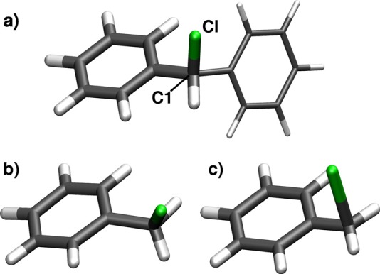
(a) Optimized geometry of the S0 minimum and visualization of the ONIOM partitioning for Ph2CH–Cl: The thicker drawn part represents the high-level system treated with CASSCF(12,10). The second phenyl ring is only included in the low-level calculations with UB3LYP. (b) Optimized geometry of the three-state CoIn for the model system with a C1-Cl distance of 2.15 Å. (c) Optimized geometry of the two-state CoIn for the model system with a C1-Cl distance of 2.58 Å.
A. Potential energy surfaces and the influence of the chlorine lone pairs
We optimized two CoIns for the model system which are shown in Figs. 2(b) and 2(c). A three-state CoIn could be located between the ππ* S1 state and both lone pair states exhibiting nπ* character with the program package COLUMBUS26–29 (see Fig. 2(b)). The C1-Cl distance is 2.15 Å, the maximum energy gap between each pair of states is 0.017 eV. A second CoIn—this time a two-state CoIn—between the S4 state of mixed ππ* and πσ* character and the ππ* state S1 is located at a C1-Cl distance of 2.58 Å with the program package Molpro30–33 (see Fig. 2(c)). Here, the energy gap is 2.4 × 10⁻⁴ eV.
First, we calculated PESs along the dissociation coordinate, the C1-Cl distance rC1Cl. Fig. 3 illustrates them in the diabatic representation as used in the QD calculations which will be discussed in Sec. II B. The bound S0 state (black) correlates with the homolytic bond cleavage leading to radical pairs. The reaction starts with a π-π* excitation to the S1 state (red). The excitation energy is 4.88 eV (254 nm), which is in good agreement with the experimental value of 4.66 eV (266 nm).20 At 2.12 Å, the lone pair states (green) cross the S1 forming a three-state CoIn and are more and more stabilized with increasing C1-Cl distance, while their character changes from nπ* to nσ*. Finally, they become degenerate with the ground state S0. Therefore, the lone pair states constitute a direct connection between the optically accessed S1 state and the homolytic product channel. After the three-state CoIn, the S1 energy increases slightly to reach the S4/S1 CoIn at 2.60 Å. The S4 state (blue) is identified as the heterolytic reaction channel for large C1-Cl distances. The S1 state finally correlates with the first excited radical channel. Altogether, two consecutive CoIns are accountable for the product splitting, and the lone pair states are the key elements here.
FIG. 3.
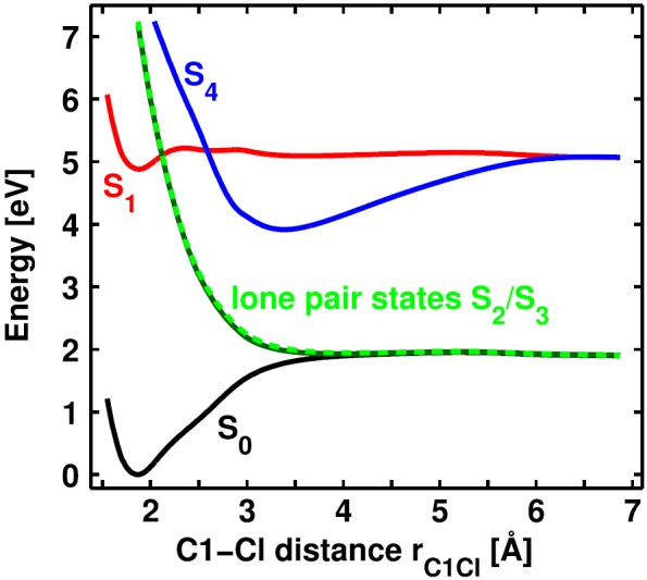
Diabatic PESs of Ph2CH–Cl calculated at the ONIOM level of theory along the C1-Cl distance rC1Cl. The S0 state (black) and the lone pair states (green) form the homolytic product channel, the S4 state (blue) forms the heterolytic product channel. The S1 state (red) leads to excited radical pairs.
To demonstrate the crucial influence of the Cl lone pairs, we performed CASSCF calculations without the Cl lone pairs being in the active space, i.e., CASSCF(8,8). At this level of theory, we optimized an additional S1/S0 CoIn for the model system which is the analog to the one identified previously,22 showing the Cl atom above an allylic subunit. We linearly interpolated the structure between the optimized S1/S0 CoIn and the S0 minimum of the model system. Based on the obtained geometries, Fig. 4 compares the resulting PESs at the CASSCF(8,8) (dashed lines) and the CASSCF(12,10) level of theory (solid lines). Around the FC region, both methods yield similar results. But as soon as the lone pair states (green solid lines) cross the S1 state (red solid line), the PESs begin to differ. In the case of CASSCF(8,8), the S1/S0 CoIn is clearly visible at rC1Cl = 3.11 Å with an energy gap of 4.96 × 10⁻⁵ eV. In contrast thereto, the S1/S0 energy gap increases to 1.59 eV at the CASSCF(12,10) level of theory because the lone pair states intrude. Nevertheless, the character of S0 and S1 is remarkably similar. Obviously, the Cl lone pairs prevent the S1/S0 CoIn observed at the CASSCF(8,8) level of theory. Instead, they open up a completely new and direct connection between S1 and S0 already in the FC region, resulting in the formation of radical pairs.
FIG. 4.
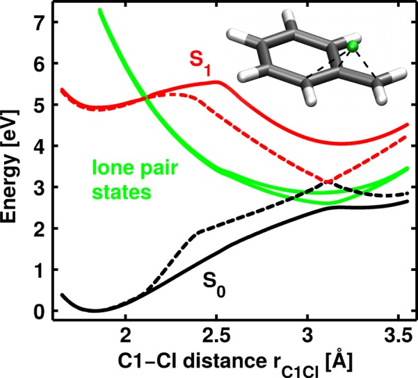
PESs for the model system of Ph2CH–Cl using two different active spaces. The dashed lines show the results for the active space containing only the π-system and the C1-Cl bond (CASSCF(8,8)). The solid lines are obtained if the Cl lone pairs are additionally included in the active space (CASSCF(12,10)). The geometries are interpolated between the S0 minimum and a S1/S0 CoIn located using CASSCF(8,8). This CoIn connects S1 (red) and S0 (black) at rC1Cl = 3.11 Å. Its geometry is depicted in the right upper corner as inlay. The lone pair states (green) which are shown as diabatic states separate S1 and S0 by 1.59 eV at the former CoIn.
B. Quantum dynamics in the presence of a three-state conical intersection
As a full dimensional quantum dynamical treatment is not feasible, we use a two-dimensional subspace to describe the reaction. The chosen coordinates are the C1-Cl distance and a coordinate accounting for the relaxation occurring in the carbon backbone during the bond cleavage. Most important is the hybridization of the central carbon atom C1 which changes from sp3 to sp2. Thus, the C1 environment gets more and more planar during the reaction. We use the pyramidalization distance dpy to measure the distance of C1 above the plane formed by its three remaining neighboring atoms as coordinate. It includes additional relevant changes during re-hybridization like adaptations of bond lengths and ring positioning. As the lone pair states are rather independent of the carbon backbone relaxation, the three-state CoIn forms a seam along the pyramidalization distance dpy (see Fig. 5).
FIG. 5.
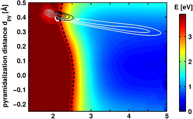
PES of the adiabatic S1 state of Ph2CH–Cl calculated at the ONIOM level of theory. Three wave packet snapshots taken from the diabatic propagation at different time points are also plotted. The first snapshot (gray isolines) is taken after 19 fs, the second (black isolines) after 36 fs, and the third (white isolines) after 82 fs. The three-state CoIn seam (black dashed line) is visible around the energy range of 3.3 eV (bright red).
Since the quantum dynamical study should include population transfer between electronic states, the calculation of coupling elements is necessary. As the two lone pair states are always nearly degenerate, there will be significant coupling throughout the whole coordinate space that is not relevant for the product formation. To avoid this omnipresent coupling, we switch to the diabatic picture where the electronic states maintain their specific character while passing a CoIn. In this picture, the coupling between the lone pair states can easily be set to zero. To transform the PESs, we solely employ ab initio molecular properties, namely, dipole and transition dipole moments forming the matrix μad. The matrix elements are functions depending on the electronic structure and thus show the same behavior at the CoIn as the electronic energy. We will briefly discuss the procedure which is based on transformations for two-state CoIns.34–36 Due to the three-state CoIn, the matrix dimension is 3 × 3.
Because the population transfer only occurs if two states come very close, it is useful to neglect the coupling far from the CoIn. Therefore, the off-diagonal terms between the states i and j are damped according to the following equation:34
| (1) |
Here, is multiplied by an exponential function depending on a damping factor f and the squared energy difference ΔEij. The damping factor f has to be chosen carefully with respect to a smooth behavior in the resulting PESs. In the present work, f = 500 for the three-state CoIn and f = 5000 to 10 000 for the two-state CoIn. The modified matrix is then diagonalized
| (2) |
and the resulting transformation matrix U is applied to obtain the diabatic energies and couplings of the matrix H (Eq. (3))
| (3) |
Ek represents the adiabatic energies.
Fig. S1 in the supplementary material37 shows the resulting two-dimensional diabatic PESs. The QD simulations were performed using the Chebychev propagation scheme38 and the Wilson G-matrix formalism39–41 (for details, see supplementary material37). The ground state vibrational eigenfunction was transferred to the S1 PES and slightly shifted to a smaller C1-Cl distance and a higher pyramidalization distance dpy to account for the minimal barrier being not contained in the ONIOM PES. Fig. 5 depicts snapshots of the wave packet at three points in time. Although the propagation is performed in the diabatic presentation, the adiabatic S1 PES is shown. This allows to place the three wave packets in the respective potential, which they experience during the propagation. The three-state CoIn seam (black dashed line) is very prominent in this representation. It is present for all values of dpy in the range of rC1Cl = 2.1 Å to rC1Cl = 2.5 Å at an energy of approximately 3.3 eV (bright red).
The first snapshot (gray isolines) is taken 19 fs after the propagation has been started and shows the wave packet at the S1 minimum in the FC region. After 36 fs (black isolines), the wave packet has already coupled through the three-state CoIn seam and starts to follow the steep gradient of the lone pair state PES toward larger rC1Cl. As there is also a small gradient in dpy toward planarization, the wave packet is slightly asymmetric in the direction of dpy. After 82 fs (white isolines), the wave packet is stretched from the three-state CoIn seam at rC1Cl = 2.1 Å to rC1Cl = 4.9 Å which results from the ongoing coupling through the three-state CoIn seam, while the first parts of the wave packet evolve very fast. It reaches a maximum C1-Cl distance of rC1Cl = 5 Å, which means that the bond cleavage is fully performed. But there still maintains a considerably large pyramidalization of dpy = 0.3 Å. This observation is in agreement with experimental observations and on-the-fly simulations which reveal that the formation of the full absorption signal of the Ph2CH+ cation occurs with a time constant of 300 fs, which is attributed to planarization and solvation effects.42
Fig. 6 illustrates the product formation obtained by the QD simulations. Therefore, the population of each state is collected at rC1Cl = 4.0 Å. It is clearly visible that the radical pairs are the main product of the initial bond cleavage. In the course of the propagation, 82% of the initial population reach the dissociation limit in the lone pair states or in the excited radical channel. At 67 fs, the radical yield starts to grow very rapidly as more and more parts of the wave packet couple through the three-state CoIn seam. This delay time is in very good agreement with the experimentally observed 76 fs.21 The delay time of 143 fs for the ion pairs is only slightly longer than the measured one of 124 fs (Ref. 21) and in excellent agreement with previous QD calculations where the lone pair states have not been considered.22 The simulated product yields deviate more from the experimental observations.5 The experimental radical yield of 40% is approximately half of the simulated yield of 82%. This may be attributed to recombination which is not considered in the simulation. On the other hand, the cation yield is underestimated with 0.2% here compared to 2% in the experiment. This might be due to the fact that the minimal barrier in the S1 state before the S4/S1 CoIn is not included in the PES. Thus, the fraction of the wave packet reaching the S4/S1 CoIn is underestimated. All in all, it is possible to successfully model the initial bond cleavage of Ph2CH–Cl with radical pairs as the main product by the sequential passage through the CoIns in the FC region and to reproduce the observed delay times very well.
FIG. 6.
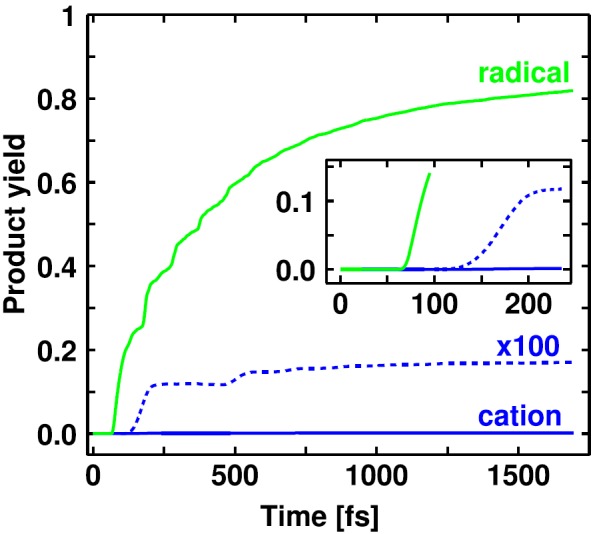
Product yield progress for the propagation of Ph2CH–Cl up to 1700 fs. The ion pair yield is additionally plotted enlarged by the factor 100 with dashed lines. The inset especially depicts the onset of the rise of the product yield curves for the first 250 fs.
The subsequent processes—in particular, electron transfer, diffusional separation, and geminate recombination—can be treated with a combined Marcus-Smoluchowski model.5 Thereto, a pair of coupled differential equations can be set up and solved numerically (for details, see Ref. 5). The secondary processes typically take place on a time scale ranging from a few picoseconds up to several nanoseconds. They determine the chemically relevant cation yield which is available for subsequent, mostly bimolecular reactions.6–8,10
III. BOND CLEAVAGE OF Ph2CH−PPh3+
In this section, we will focus on the bond cleavage of , which contains as LG in contrast to the previously investigated Ph2CH–Cl. At first sight, the exchange of the LG introduces four major modifications: First, the moiety is considerably larger than the Cl atom. Second, it carries a positive charge. Third, the additional phenyl rings on the LG can be excited at a similar energy as the Ph2CH moiety and thus are competing chromophores. And fourth, in contrast to the Cl, the P atom does not posses any lone pairs which have shown to be of great importance for the bond cleavage of Ph2CH–Cl. Altogether, these changes coming along with the exchange of the Cl atom with the moiety already indicate changes of the key features during the bond cleavage.
A. Potential energy surfaces and a second chromophore carrying a positive charge
Initially, we take a look at the optical excitation process. As already mentioned, the phenyl rings of the moiety constitute additional chromophores, which absorb in the same spectral region as the phenyl rings of the Ph2CH moiety. This results in an increased excited state manifold. The full system exhibits five locally excited states which are energetically quite close—two on the Ph2CH moiety and three on the LG.43 In addition, charge transfer excitations between both moieties are present. They are energetically well separated from the locally excited states and higher in energy.43 Like in the case of Ph2CH–Cl, the PESs for the QD calculations are evaluated at the ONIOM level of theory. The characteristics of in the FC region—in particular, the charge transfer states—already reveal that the high-level system has to contain not only one phenyl ring of the Ph2CH moiety but also one of the moiety. Thus, the interplay between locally excited and charge transfer states can be described. Fig. 7(a) shows the ground state minimum structure of . The thick part of the molecule is the high-level system phenylmethylphenylphosphonium ion (PhCH2–PH2Ph+), while the thinner phenyl rings are only contained in the low-level system. The high-level system is calculated at the CASSCF(10,10) level of theory. The active space contains two π- and two π*-orbitals of each phenyl ring as well as the σ- and σ*-orbitals of the C1-P bond.43 The low-level system is evaluated at the density functional theory (DFT) level of theory (functional M06-2X44).
FIG. 7.
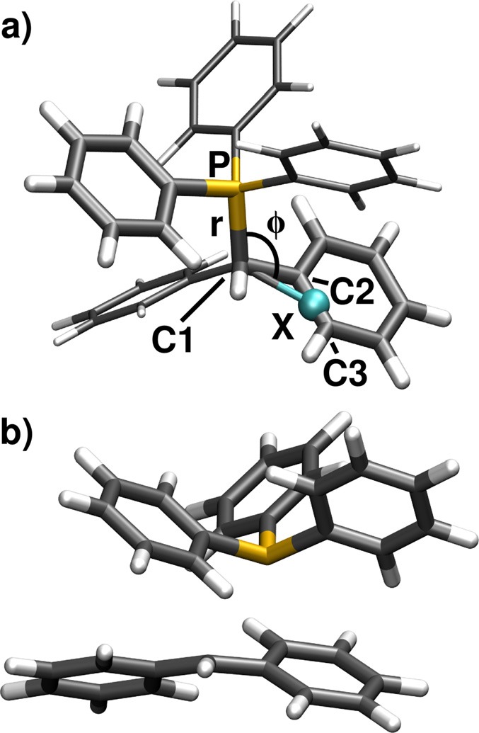
(a) Ground state minimum geometry of optimized at the DFT level of theory (functional B3LYP). The thicker drawn part of the molecule constitutes the high-level system of the ONIOM calculations, while the thinner drawn phenyl rings are only contained in the low-level system. (b) Geometry of the S1/S0 CoIn of calculated at the ONIOM level of theory.
Fig. 8 illustrates the PES of the four lowest singlet states along the C1-P distance rC1P for a constant P-C1-X angle (see Fig. 7). A local π-π* excitation on leads to the S1 state (red line), while the S2 (blue line) is characterized by a local π-π* excitation on the Ph2CH moiety. The S3 state (orange line) has charge transfer character in the FC region. To observe bond cleavage experimentally, the system is excited to the locally excited states.4 The S1 state opens the preferred reaction path compared to the S2 as first it has the lower barrier, and second the S2 population can immediately relax to the S1 via a S2/S1 CoIn.43 Therefore, we will focus on the S1 state from now on. At a C1-P distance of rC1P = 2.1 Å, the S1 state exhibits a barrier of 0.3 eV. Here, the S1 character changes to πσ* followed by a change to a σσ* character. This is in clear contrast to the excited state bond cleavage of Ph2CH–Cl, where the Cl lone pairs induce the strong energetic stabilization of the adiabatic S1 state after the three-state CoIn. In the dissociation limit, the ground state S0 of has heterolytic character leading to Ph2CH+ + PPh3, whereas the first and second excited state—S1 and S2—have homolytic character. They result in the formation of radical pairs: diphenylmethyl radicals . This is the second major difference with respect to the Cl leaving group, where the S0 has homolytic and the S1 heterolytic character. The difference can be traced back to the initial positive charge of , which leads to one positively charged and one neutral fragment in both (homolytic and heterolytic) dissociation channels. Thus, no charge separation occurs during the bond cleavage, which is the major reason for the destabilization of the heterolytic channel in Ph2CH–Cl.
FIG. 8.
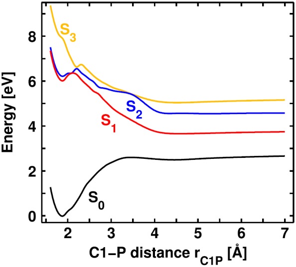
Potential energy surface of the four lowest singlet states of along the C1-P distance rC1P calculated at the ONIOM level of theory. The P-C1-X angle is kept constant at .
Due to the lack of lone pairs at the P atom, the three-state CoIn which is present in the FC region of Ph2CH–Cl disappears completely in as mentioned above. But at the same time, an energetically low lying two-state CoIn between S1 and S0 can be optimized in the high-level system PhCH2–PH2Ph+, which is located at a larger C1-P distance.43 The P atom is located above an allylic C3 subunit containing C1, C2, and C3 showing a related geometry to the S1/S0 CoIn of Ph2CH–Cl calculated at the CASSCF(8,8) level of theory. For the full system , this S1/S0 CoIn is depicted in Fig. 7(b). The C1-P distance is rC1P = 2.9 Å; the P-C1-X angle is . The energy difference between S1 and S0 is 0.085 eV at the ONIOM level of theory. In the case of Ph2CH–Cl, the CoIn was prevented by the Cl lone pairs (cf. Fig. 4). After the photoexcitation of , the experimentally observed main products are Ph2CH+ and PPh3.4 Hence, the system has to relax to the ground state during the bond cleavage process because only there the Ph2CH+ are formed. The localized S1/S0 CoIn offers a fast way for the system to reach the S0.
In order to test the efficiency of the S1/S0 CoIn by QD simulations, like in Ph2CH–Cl, a two-dimensional subspace is chosen in such a way that the CoIn can be described.18,19 Besides the C1-P distance rC1P, an angular motion of the LG is necessary to reach the structure of the CoIn.43 Thus, the P-C1-X angle shown in Fig. 7(a) is introduced as the second coordinate. The dummy atom X is placed in such a way in the allylic plane at the optimized CoIn of PhCH2–PH2Ph+ that the angle optimally leads to the CoIn.45 The relaxation of the carbon backbone of the Ph2CH moiety which is the second coordinate in the case of Ph2CH–Cl is embedded into the rC1P coordinate.45 As a result, the CoIn shown in Fig. 7(b) is contained in the ONIOM PES.
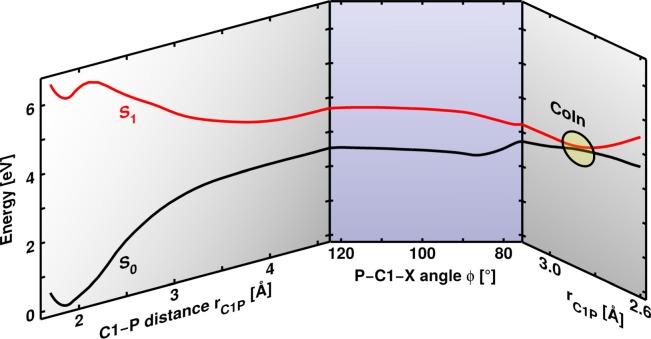
Fig. 9 shows a one-dimensional representation of the minimum energy path (MEP) in the S1 state in the two-dimensional subspace at the ONIOM level of theory. The first part on the left side starts in the FC region and is depicted depending on rC1P. After crossing the barrier, the system moves mainly along rC1P gaining about 2.6 eV of potential energy. Simultaneously, the energy of the ground state rises by 2.5 eV. In the second part (middle), where the primary motion is along , the energy of both electronic states remains almost constant. Only from to , the S1 energy lowers by approximately 0.36 eV. The last part of the MEP (right) is depicted again depending on rC1P. A shortening of the C1-P distance to rC1P = 2.9 Å finally leads to the S1/S0 CoIn, where in principle the S1 population can be transferred to the ground state to generate Ph2CH+. The S1 MEP emphasizes the fact that the system has to move considerably along . The key question is whether the motion from the FC region toward the CoIn is possible despite the large initial gradient along rC1P.
FIG. 9.
Minimum energy path in the first excited state S1 (red line) for the bond cleavage of in the two-dimensional coordinate space . The ground state S0 is depicted in black. The PES is displayed in three parts along the respective mainly changing coordinate. The first and the third part primarily involve changes in rC1P, while in the second part the major motion is along .
B. Quantum dynamics influenced by the solvent cage
We could show that the molecular PES does not allow for the change of momentum from the rC1P to the coordinate necessary to reach the CoIn.18 As the experiments are performed in solution, the solvent has to be considered in the simulation. In the case of , both dissociation channels lead to one positively charged and one neutral fragment. Therefore, electrostatic solvent effects are insignificant.43 Only dynamic solvent effects can come into play.18,19
Thereby, the solvent cage prevents the free dissociation of the fragments and decelerates the motion along rC1P. These dynamic solvent effects can be accounted for in QD calculations by means of an additional potential term in the Hamiltonian ,18,19
| (4) |
with the kinetic energy operator and the molecular potential . Recently, we developed two different approaches with increasing complexity to calculate the solvent potential . The first method includes the solvent effects in a continuum-like fashion,18 the second treats the solvent environment explicitly.19 We will give a brief overview of both methods in the following.
In the dynamic continuum ansatz, Stokes' law is employed to calculate a decelerating force which acts on the wave packet. Thereto, the dynamic viscosity of the solvent η together with the expectation value of velocity of the wave packet and an effective radius Reff are needed
| (5) |
Reff takes into account the different masses and radii of the generated fragments. To guarantee a deceleration of the wave packet only in an area where the solvent cavity is deformed, the actual decelerating force Fdec(r, t) is obtained by multiplication of F0(t) with a sigmoid shape function. It was fitted to the course of the cavity surface area along the major bond cleavage coordinate rC1P. Finally, an integration of Fdec(rC1P, t) over rC1P yields the solvent potential Vsolv,
| (6) |
In addition to the usual spatial dependence of a potential, Vsolv(rC1P, t) is time-dependent. This is due to the time-dependence of the expectation value of velocity and describes the deceleration decrease with reducing velocity. For a more detailed description, see Ref. 18.
The second method, the QD/MD approach, combines QD calculations with molecular dynamics (MD) simulations of the solvent environment.19 Randomly selected snapshots from the MD trajectories give an averaged picture of the atomistic solvent surrounding of the reactant. The solvent potential Vsolv is calculated for each snapshot individually. It contains the quantum chemically calculated interaction energy Esf between each of the two fragments and each solvent molecule
| (7) |
with Nfrag and Nsolv being the number of fragments and solvent molecules, respectively. For each thus obtained Vsolv, a QD simulation is conducted. The average of all wave packet propagations describes the effect of the solvent environment. More details to the QD/MD approach can be found in Ref. 19.
Here, we want to focus on the results obtained with the dynamic continuum ansatz. Acetonitrile is used as solvent with its dynamic viscosity of η = 0.343 mPas at 25 °C. But first of all, let us take a look at the bond cleavage process in the molecular potential without taking the solvent into account. Fig. 10(a) shows the S1 PES together with snapshots from different QD simulations. The snapshots depicted by the dark gray and the black isolines are obtained by a QD simulation using only the molecular potential. They are taken 170 fs (dark gray) and 290 fs (black) after the wave packet started in the FC region. Obviously, the wave packet misses the CoIn as the initial gain of momentum in the rC1P direction is too large to be compensated by the comparably small gradient toward the CoIn. Thus, the system dissociates in the first excited state, and radical pairs are generated.18 This is in clear contrast to the experimental observations in solution where Ph2CH+ cations are the main product.4
FIG. 10.
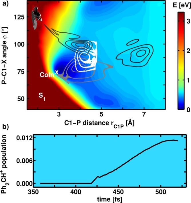
(a) Potential energy surface of the S1 state of calculated at the ONIOM level of theory. The S0 minimum is located at rC1P = 1.87 Å and . In addition, snapshots from two different wave packet propagations are shown: The dark gray and black isolines depict wave packets from a normal propagation taken at 170 fs (dark gray) and 290 fs (black) after starting in the FC region. The white and light gray isolines display wave packets from a QD simulation with the dynamic continuum ansatz. They are taken at 290 fs (white) and 390 fs (light gray) after starting in the FC region. (b) Population of the S0 state which evolves toward larger rC1P values after coupling through the CoIn finally leading to Ph2CH+ cation generation.
Fig. 10(a) displays two additional wave packet snapshots obtained from a propagation with the dynamic continuum ansatz. The snapshots are taken at 290 fs (white isolines) and 390 fs (light gray isolines) after starting in the FC region. The white isolines show the wave packet after the same propagation time as the black isolines for the QD simulation without the solvent potential. It is clearly visible that the motion along rC1P is decelerated due to the solvent surrounding. Thus, the wave packet can experience the small gradient toward the CoIn and approaches it after approximately 390 fs. Here, the S1 population can relax to the ground state where finally the formation of the experimentally observed Ph2CH+ cations takes place. Fig. 10(b) shows the rise of the Ph2CH+ cation population in the ground state after transfer through the S1/S0 CoIn calculated in the adiabatic picture.18 The population rise between 400 and 500 fs compares well with the experimentally observed initial rise of the cation absorption signal.4
IV. SUMMARY
We theoretically investigated the initial bond cleavage process in two Ph2CH derivatives, namely, Ph2CH–Cl and . By means of quantum chemical calculations, we first identified the individual molecular features of both precursors, which are clearly depending on the LG. Based on the knowledge of the important stationary points, we calculated PESs at the ONIOM level of theory and performed two-dimensional QD simulations.
The lowest excited state of both molecules is characterized by a local π-π* excitation on one phenyl ring. In the case of Ph2CH–Cl, it is located on the Ph2CH moiety; in the case of on the LG. These local ππ* S1 states initiate the bond cleavage. We showed that for Ph2CH–Cl the Cl lone pairs have a decisive impact on the molecular features in the FC region. Two successive CoIns determine the product formation at a very early stage of the bond cleavage. The first CoIn is a three-state CoIn which includes the lone pair states and opens the homolytic reaction channel, resulting in the formation of . The second CoIn—this time a two-state CoIn—occurs at a slightly elongated C1-Cl distance and leads to the heterolytic channel with Ph2CH+ + Cl−. QD simulations on the diabatic PESs reveal an extremely fast and efficient formation of within 67 fs. This delay time is in very good agreement with the observed 76 fs.21 The ion pair formation takes place on a slightly longer time scale of 143 fs compared to the experimental value of 124 fs and is like in the experiment the minor product channel. Our QD simulation shows the key role of the three-state CoIn seam during the photoinduced bond cleavage of Ph2CH–Cl and compares well with the experiment.
Changing the LG to results in significantly different molecular features. As the LG does not possess any lone pairs, the corresponding states being decisive in Ph2CH–Cl do not exist. Instead, we localized a two-state CoIn at longer C1-P distance far beyond the FC-region which connects both reaction channels. QD simulations for the isolated molecule show that the wave packet misses the CoIn and dissociates in the S1 state which has homolytic character. Thus, radical pairs are generated which is in contrast to the experimentally observed formation of Ph2CH+ cations.4 Only if the dynamic solvent effects are taken into account which lead to a deceleration of the wave packet during dissociation, the molecular system can follow the slight gradient toward the CoIn and reaches it after approximately 390 fs. Here, the S1 population can relax to the ground state which has heterolytic character in the dissociation limit. The simulated onset of the Ph2CH+ population is in accordance with the initial rise of the Ph2CH+ absorption signal in the experiment.4
In a simplistic concept of photoinduced bond cleavage, the LG has just the function to leave the precursor and form a fragment, which is as stable as possible in the desired product channel. Our results impressively demonstrate that changing the LG may introduce far more extensive changes of the molecular features which set the stage for the bond cleavage process. In the presented cases of Ph2CH–Cl and , the LG controls the position of the CoIns which decide the branching for the product formation. Furthermore, the delay time until the products are formed also depends on the spatial and energetic position of the CoIns. In addition, the LG influences the environmental impact on the reaction. In the case of , the solvent cage decelerates the wave packet on the sub-picosecond time scale, and only thus enables a coupling through the CoIn to form the Ph2CH+ cations. The influence of the solvent environment occurs on a longer time scale for Ph2CH–Cl. Here, an electron transfer subsequent to the initial bond cleavage described in the present work leads to Ph2CH+ generation. This electron transfer is strongly depending on the polarity of the solvent. Changing the LG of Ph2CH derivatives from neutral to charged does not only modify the stability of the isolated fragments after bond cleavage, it also alters the molecular response and reaction outcome on the femtosecond time scale. Thus, a minor chemical change leads to a substantial change in the femtochemistry of the system.
ACKNOWLEDGMENTS
Financial support by the Deutsche Forschungsgemeinschaft through the SFB749 and the excellence cluster Munich-Centre for Advanced Photonics (MAP) is acknowledged. We thank Benjamin Fingerhut, Eberhard Riedle, Christian Sailer, Herbert Mayr, and Johannes Ammer for fruitful discussions.
References
- 1. Bartl J., Steenken S., Mayr H., and McClelland R. A., J. Am. Chem. Soc. 112, 6918 (1990). 10.1021/ja00175a028 [DOI] [Google Scholar]
- 2. Das P. K., Chem. Rev. 93, 119–144 (1993). 10.1021/cr00017a007 [DOI] [Google Scholar]
- 3. McClelland R. A., Tetrahedron 52, 6823–6858 (1996). 10.1016/0040-4020(96)00020-8 [DOI] [Google Scholar]
- 4. Ammer J., Sailer C. F., Riedle E., and Mayr H., J. Am. Chem. Soc. 134, 11481–11494 (2012). 10.1021/ja3017522 [DOI] [PubMed] [Google Scholar]
- 5. Sailer C. F., Thallmair S., Fingerhut B. P., Nolte C., Ammer J., Mayr H., Pugliesi I., de Vivie-Riedle R., and Riedle E., ChemPhysChem 14, 1423 (2013). 10.1002/cphc.201201057 [DOI] [PubMed] [Google Scholar]
- 6. Ammer J. and Mayr H., J. Phys. Org. Chem. 26, 956–969 (2013). 10.1002/poc.3132 [DOI] [Google Scholar]
- 7. Mayr H., Tetrahedron 71, 5095–5111 (2015). 10.1016/j.tet.2015.05.055 [DOI] [Google Scholar]
- 8. Mayr H. and Patz M., Angew. Chem., Int. Ed. 33, 938–957 (1994). 10.1002/anie.199409381 [DOI] [Google Scholar]
- 9. Mayr H., Bug T., Gotta M. F., Hering N., Irrgang B., Janker B., Kempf B., Loos R., Ofial A. R., Remennikov G., and Schimmel H., J. Am. Chem. Soc. 123, 9500–9512 (2001). 10.1021/ja010890y [DOI] [PubMed] [Google Scholar]
- 10. Mayr H., Ammer J., Baidya M., Maji B., Nigst T. A., Ofial A. R., and Singer T., J. Am. Chem. Soc. 137, 2580–2599 (2015). 10.1021/ja511639b [DOI] [PubMed] [Google Scholar]
- 11. Coe J. D., Ong M. T., Levine B. G., and Martínez T. J., J. Phys. Chem. A 112, 12559 (2008). 10.1021/jp806072k [DOI] [PubMed] [Google Scholar]
- 12. González-Vázquez J. and González L., ChemPhysChem 11, 3617–3624 (2010). 10.1002/cphc.201000557 [DOI] [PubMed] [Google Scholar]
- 13. Krause P. and Matsika S., J. Chem. Phys. 136, 034110 (2012). 10.1063/1.3677273 [DOI] [PubMed] [Google Scholar]
- 14. Svensson M., Humbel S., Froese R. D. J., Matsubara T., Sieber S., and Morokuma K., J. Phys. Chem. 100, 19357–19363 (1996). 10.1021/jp962071j [DOI] [Google Scholar]
- 15. Dapprich S., Komáromi I., Byun K., Morokuma K., and Frisch M. J., J. Mol. Struct.: THEOCHEM 461–462, 1–21 (1999). 10.1016/S0166-1280(98)00475-8 [DOI] [Google Scholar]
- 16. Vreven T. and Morokuma K., J. Chem. Phys. 113, 2969 (2000). 10.1063/1.1287059 [DOI] [Google Scholar]
- 17. Bearpark M. J., Larkin S. M., and Vreven T., J. Phys. Chem. A 112, 7286 (2008). 10.1021/jp802204w [DOI] [PubMed] [Google Scholar]
- 18. Thallmair S., Kowalewski M., Zauleck J. P. P., Roos M. K., and de Vivie-Riedle R., J. Phys. Chem. Lett. 5, 3480–3485 (2014). 10.1021/jz501718t [DOI] [PubMed] [Google Scholar]
- 19. Thallmair S., Zauleck J. P. P., and de Vivie-Riedle R., J. Chem. Theory Comput. 11, 1987–1995 (2015). 10.1021/acs.jctc.5b00046 [DOI] [PubMed] [Google Scholar]
- 20. Peters K. S., Chem. Rev. 107, 859 (2007). 10.1021/cr068021k [DOI] [PubMed] [Google Scholar]
- 21. Sailer C. F., Krebs N., Fingerhut B. P., de Vivie-Riedle R., and Riedle E., EPJ Web Conf. 41, 05042 (2013). 10.1051/epjconf/20134105042 [DOI] [Google Scholar]
- 22. Fingerhut B. P., Geppert D., and de Vivie-Riedle R., Chem. Phys. 343, 329 (2008). 10.1016/j.chemphys.2007.07.034 [DOI] [Google Scholar]
- 23. Manring L. E. and Peters K. S., J. Phys. Chem. 88, 3516–3520 (1984). 10.1021/j150660a028 [DOI] [Google Scholar]
- 24. Bizjak T., Karpiuk J., Lochbrunner S., and Riedle E., J. Phys. Chem. A 108, 10763–10769 (2004). 10.1021/jp0473772 [DOI] [Google Scholar]
- 25. Frisch M. J., Trucks G. W., Schlegel H. B., Scuseria G. E., Robb M. A., Cheeseman J. R., Scalmani G., Barone V., Mennucci B., Petersson G. A., Nakatsuji H., Caricato M., Li X., Hratchian H. P., Izmaylov A. F., Bloino J., Zheng G., Sonnenberg J. L., Hada M., Ehara M., Toyota K., Fukuda R., Hasegawa J., Ishida M., Nakajima T., Honda Y., Kitao O., Nakai H., Vreven T., J. A. Montgomery, Jr. , Peralta J. E., Ogliaro F., Bearpark M., Heyd J. J., Brothers E., Kudin K. N., Staroverov V. N., Kobayashi R., Normand J., Raghavachari K., Rendell A., Burant J. C., Iyengar S. S., Tomasi J., Cossi M., Rega N., Millam J. M., Klene M., Knox J. E., Cross J. B., Bakken V., Adamo C., Jaramillo J., Gomperts R., Stratmann R. E., Yazyev O., Austin A. J., Cammi R., Pomelli C., Ochterski J. W., Martin R. L., Morokuma K., Zakrzewski V. G., Voth G. A., Salvador P., Dannenberg J. J., Dapprich S., Daniels A. D., Farkas Ö., Foresman J. B., Ortiz J. V., Cioslowski J., and Fox D. J., “Gaussian 09, Revision D.01, Gaussian, Inc., Wallingford CT, 2009” (2009).
- 26. Lischka H., Shepard R., Shavitt I., Pitzer R. M., Dallos M., Müller T., Szalay P. G., Brown F. B., Ahlrichs R., Böhm H. J., Chang A., Comeau D. C., Gdanitz R., Dachsel H., Ehrhardt C., Ernzerhof M., Höchtl P., Irle S., Kedziora G., Kovar T., Parasuk V., Pepper M. J. M., Scharf P., Schiffer H., Schindler M., Schüler M., Seth M., Stahlberg E. A., Zhao J.-G., Yabushita S., Zhang Z., Barbatti M., Matsika S., Schuurmann M., Yarkony D. R., Brozell S. R., Beck E. V., Blaudeau J.-P., Ruckenbauer M., Sellner B., Plasser F., and Szymczak J. J., “COLUMBUS, an ab initio electronic structure program, release 7.0” (2013).
- 27. Manaa M. R. and Yarkony D. R., J. Chem. Phys. 99, 5251 (1993). 10.1063/1.465993 [DOI] [Google Scholar]
- 28. Matsika S. and Yarkony D. R., J. Chem. Phys. 117, 6907 (2002). 10.1063/1.1513304 [DOI] [Google Scholar]
- 29. Dallos M., Lischka H., Shepard R., Yarkony D. R., and Szalay P. G., J. Chem. Phys. 120, 7330 (2004). 10.1063/1.1668631 [DOI] [PubMed] [Google Scholar]
- 30. Werner H.-J., Knowles P. J., Knizia G., Manby F. R., Schütz M., Celani P., Korona T., Lindh R., Mitrushenkov A., Rauhut G., Shamasundar K. R., Adler T. B., Amos R. D., Bernhardsson A., Berning A., Cooper D. L., Deegan M. J. O., Dobbyn A. J., Eckert F., Goll E., Hampel C., Hesselmann A., Hetzer G., Hrenar T., Jansen G., Köppl C., Liu Y., Lloyd A. W., Mata R. A., May A. J., McNicholas S. J., Meyer W., Mura M. E., Nicklass A., O'Neill D. P., Palmieri P., Peng D., Pflüger K., Pitzer R., Reiher M., Shiozaki T., Stoll H., Stone A. J., Tarroni R., Thorsteinsson T., and Wang M., “MOLPRO, version 2012.1, a package of ab initio programs” (2012).
- 31. Bearpark M. J., Robb M. A., and Schlegel H. B., Chem. Phys. Lett. 223, 269–274 (1994). 10.1016/0009-2614(94)00433-1 [DOI] [Google Scholar]
- 32. Eckert F., Pulay P., and Werner H.-J., J. Comput. Chem. 18, 1473–1483 (1997). [DOI] [Google Scholar]
- 33. Sicilia F., Blancafort L., Bearpark M. J., and Robb M. A., J. Chem. Theory Comput. 4, 257–266 (2008). 10.1021/ct7002435 [DOI] [PubMed] [Google Scholar]
- 34. Werner H.-J. and Meyer W., J. Chem. Phys. 74, 5802 (1981). 10.1063/1.440893 [DOI] [Google Scholar]
- 35. Dobbyn A. J. and Knowles P. J., Mol. Phys. 91, 1107 (1997). 10.1080/002689797170842 [DOI] [Google Scholar]
- 36. Kryachko E. S. and Yarkony D. R., Int. J. Quantum Chem. 76, 235 (2000). [DOI] [Google Scholar]
- 37.See supplementary material at http://dx.doi.org/10.1063/1.4941600E-SDTYAE-3-012693 for the two-dimensional diabatic PES of diphenylmethylchloride (Fig. S1), details of the QD simulations, and optimized geometries.
- 38. Tal-Ezer H. and Kosloff R., J. Chem. Phys. 81, 3967 (1984). 10.1063/1.448136 [DOI] [Google Scholar]
- 39. Podolsky B., Phys. Rev. 32, 812 (1928). 10.1103/PhysRev.32.812 [DOI] [Google Scholar]
- 40. E. B. Wilson, Jr. , Decius J. C., and Cross P. C., Molecular Vibrations: The Theory of Infrared and Raman Vibrational Spectra ( Dover Publications, New York, 1980). [Google Scholar]
- 41. Schaad L. and Hu J., J. Mol. Struct.: THEOCHEM 185, 203 (1989). 10.1016/0166-1280(89)85014-6 [DOI] [Google Scholar]
- 42. Fingerhut B. P., Sailer C. F., Ammer J., Riedle E., and de Vivie-Riedle R., J. Phys. Chem. A 116, 11064–11074 (2012). 10.1021/jp300986t [DOI] [PubMed] [Google Scholar]
- 43. Thallmair S., Fingerhut B. P., and de Vivie-Riedle R., J. Phys. Chem. A 117, 10626–10633 (2013). 10.1021/jp403082r [DOI] [PubMed] [Google Scholar]
- 44. Zhao Y. and Truhlar D., Theor. Chem. Acc. 120, 215–241 (2008). 10.1007/s00214-007-0310-x [DOI] [Google Scholar]
- 45. Thallmair S., Roos M. K., and de Vivie-Riedle R., “ The design of specially adapted reactive coordinates to economically compute potential and kinetic energy operators including geometry relaxation” (unpublished). [DOI] [PubMed]
Associated Data
This section collects any data citations, data availability statements, or supplementary materials included in this article.
Data Citations
- See supplementary material at http://dx.doi.org/10.1063/1.4941600E-SDTYAE-3-012693 for the two-dimensional diabatic PES of diphenylmethylchloride (Fig. S1), details of the QD simulations, and optimized geometries.


