Abstract
To assess facial form, one has to determine the size, position, orientation, shape, and symmetry of the different facial units. Many of these assessments require a frame of reference. The customary coordinate system used for these assessments is the ‘standard anatomical frame of reference’, a three-dimensional Cartesian system made by three planes: the sagittal, the axial, and the coronal. Constructing the sagittal plane seems simple, but because of universal facial asymmetry, it is complicated. Depending on the method one selects, one can build hundreds of different planes, never knowing which one is correct. This conundrum can be solved by estimating the sagittal plane a patient would have had if his or her face had developed symmetrically. We call this the ‘primal sagittal plane’. To estimate this plane we have developed a mathematical algorithm called LAGER (Landmark Geometric Routine). In this paper, we explain the concept of the primal sagittal plane and present the structure of the LAGER algorithm.
Keywords: primal frame of reference, primal sagittal plane, midsagittal plane, three-dimensional, head, anatomical, geometry, deformity quantification, orthognathic, craniomaxillofacial, dentofacial
Introduction
At first glance, building a sagittal plane for a head seems simple. This simplicity stems from the fact that when we envision this task, we picture doing it on a perfectly symmetrical subject. Unfortunately, no human head is perfectly symmetrical1,2. In facial asymmetry, we can build hundreds of different sagittal planes, not knowing which one is correct.
So, how can we build a sagittal plane for an asymmetric head? One solution is to use the ‘orthogonal best-fit method’. In this method, a computer algorithm first creates a three-dimensional (3D) Cartesian system comprised of three orthogonal planes. Then the algorithm translates and rotates the frame of reference until the sum of distances between the planes and key craniofacial landmarks is minimal. Unfortunately, the orthogonal best-fit method is flawed.
Another solution for building a sagittal plane for patients with asymmetric heads is to use the natural head posture (NHP)4,6. Unfortunately, the NHP method is inconsistent for two reasons. First, some patients have difficulty aligning their heads in the NHP. Second, even within the same patient, there are temporal variations in the NHP.
In order to solve this clinical problem, we first sought to answer a fundamental question: What is the ideal plane of symmetry for any patient? At conception, our genes are programmed to produce perfect facial symmetry, yet this never occurs. We know this because no individual has perfect facial symmetry1,2. To various degrees, we are all asymmetric; a multitude of stressors influence craniofacial development, resulting in asymmetry. Yet to measure facial deformity and to plan its correction there is no better frame of reference than the one a subject would have had if he or she did not have asymmetry3. We call this the ‘primal frame of reference’.
To estimate this plane we have developed a mathematical algorithm called LAGER (Landmark Geometric Routine). In this paper, we explain the concept of the primal sagittal plane and present the structure of the LAGER algorithm.
Estimation of the primal sagittal plane
The estimation of the primal sagittal plane is a challenging and fascinating problem. Fortunately, we have made significant progress, and now have a method that works very well in most circumstances. We have codified the solution in an algorithm we call LAGER, for Landmark Geometric Routine.
Landmark Geometric Routine (LAGER)
The goal of LAGER is to estimate the best plane of symmetry for an asymmetric individual. As its name implies, it uses landmarks—discrete anatomical points—for its calculations. The sagittal plane (the plane of symmetry of the body) can be easily calculated for an individual with body symmetry. The difficulty arises when the body is asymmetric. In this circumstance, asymmetric landmarks skew the sagittal plane. Yet removing the displaced landmarks can prevent the distortion. Our algorithm uses this principle to determine the best plane of symmetry.
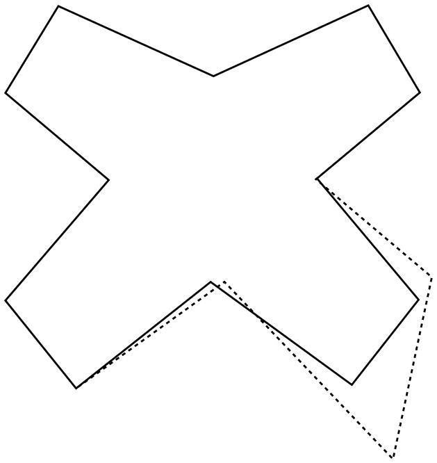
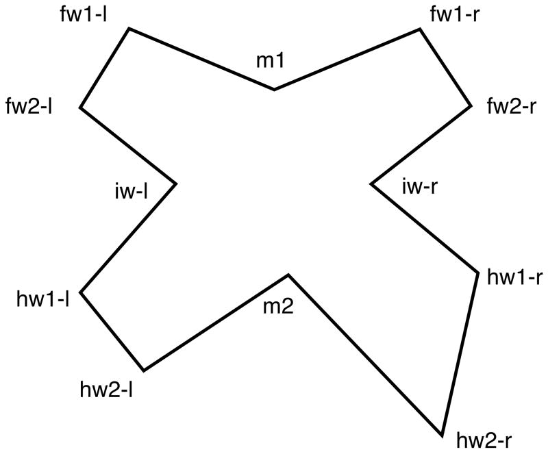
LAGER is easier to comprehend by looking at a simple example. Consider a young butterfly that is exposed to pesticides early in life. Because of the exposure, its right hind-wing overgrows (Fig. 1). We get to see the butterfly, for the first time, as a deformed adult. To analyze its form, we take a picture looking at it from above. On the picture, we identify two midline landmarks and five bilateral landmarks. The midline landmarks m1 and m2 delimit the butterfly’s body, m1 being anterior and m2 being posterior. The bilateral landmarks demarcate the outline of the wings (Fig. 2).
Fig. 1.
A young butterfly (solid line) grows abnormally (dashed line). Its right hind-wing overgrows. The dashed drawing is scaled down to show the differences in shape.
Fig. 2.
The mature butterfly as seen for the first time by an observer. Two midline landmarks (m1 and m2) delimit the body. Five bilateral landmarks delineate the wings: forewing 1 (fw1), forewing 2 (fw2), interwing (iw), hind-wing 1 (hw1), and hind-wing 2 (hw2); ‘-r’ denotes right, ‘-l’ denotes left.
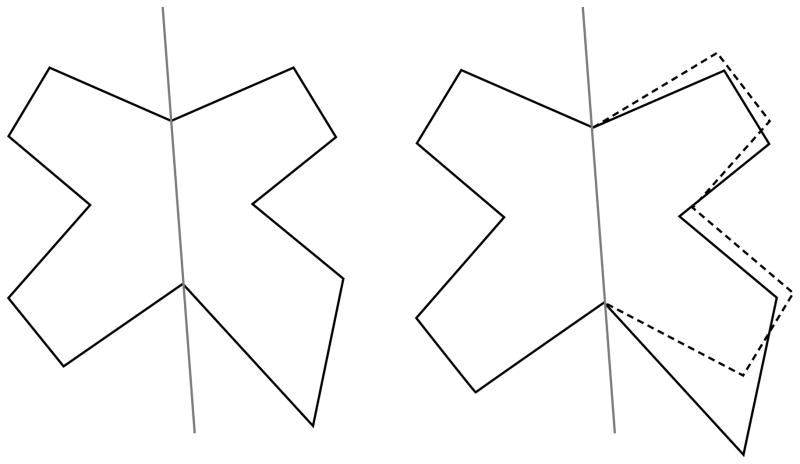
When trying to examine the butterfly’s asymmetry, our first inclination is to compare the right and left sides after we have superimposed them. For the superimposition, we will most likely fold one of the butterfly’s sides on its body axis—the line demarcated by m1 and m2. As a result of the assessment, we will conclude that the forewings and the hind-wings are asymmetric (Fig. 3). Yet we know that only the hind-wing was deformed (Fig. 1).
Fig. 3.
Our tendency is to evaluate the butterfly’s form by superimposing one side over the other. For the superimposition, we will fold one of the sides over the visible midline. This analysis will lead us to conclude that both the forewing and the hind-wing are deformed. Yet we know this is not true.
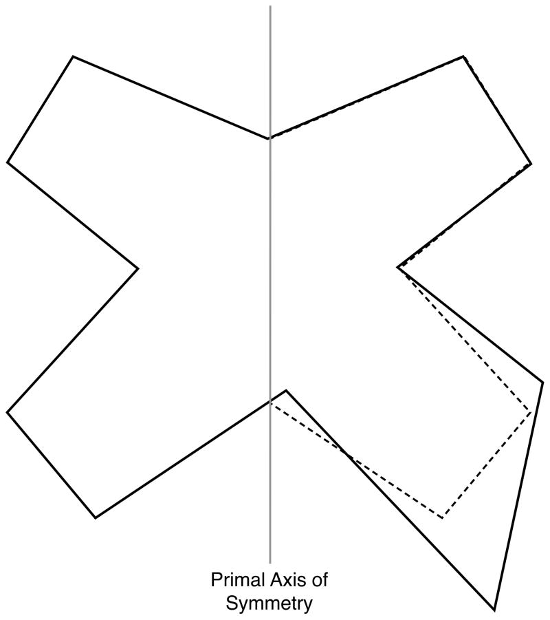
But what if we knew the primal sagittal plane for the butterfly? Would an analysis of form based on this plane have shown us the truth? Conveniently, our butterfly is synthetic (a man-made thought experiment). Thus, we can answer this question. In Fig. 4, we superimpose the right and left sides of the butterfly by folding one of its sides on the primal axis of symmetry. As you can see, this approach correctly shows that the forewings are symmetrical, only the hind-wings are uneven.
Fig. 4.
If we fold one side of the butterfly on the primal midline (the one the butterfly had before it became asymmetric) we will correctly deduce that only the hind-wing is deformed.
LAGER estimates the best plane of symmetry in three steps. The first step scores all landmarks for their degree of asymmetry, the second step removes the most asymmetric landmarks, and the third step calculates the sagittal plane.
To detect asymmetric structures, LAGER uses a Procrustes method5,7. Geometric objects have four basic characteristics: size, location, orientation, and shape. An ordinary Procrustes analysis is a mathematical method that detects shape differences between similar objects. The analysis begins by superimposing the objects optimally. For the superimposition, the objects are first translated to the same location. Next, they are scaled to the same size. Then, one of them is kept static as a target, while the other is rotated until the sum of the (squared) distances between corresponding landmarks is minimized.
At times, rather than looking for differences in shape, one is interested in comparing forms—form being the combination of size and shape. To compare forms, a Procrustes superimposition does not scale the objects to the same size. This is the type of Procrustes superimposition we codified in LAGER.
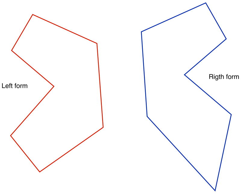
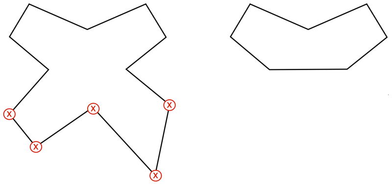
We begin the Procrustes analysis of symmetry by dividing the form of the whole butterfly into two half-forms: right and left. To divide the form, the landmarks of the whole form are divided into two groups: the right set containing all the right landmarks, as well as all the midline landmarks, and the left set containing all left landmarks and again the midline landmarks (Fig. 5).
Fig. 5.
LAGER divides the butterfly into two half-forms: right and left.
Next, using a series of maneuvers (transformations), we superimpose the two half-forms. However, before starting, we have to pick one half-form to be the object of the transformations and the other as the target. Which half-form (right or left) becomes the object is inconsequential. In this example, we transform the right half-form; the left remains as the target.
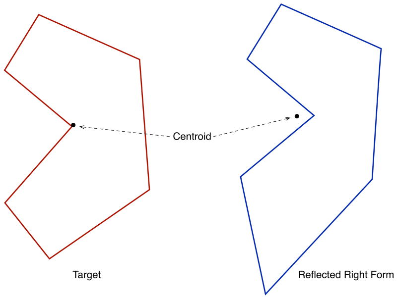
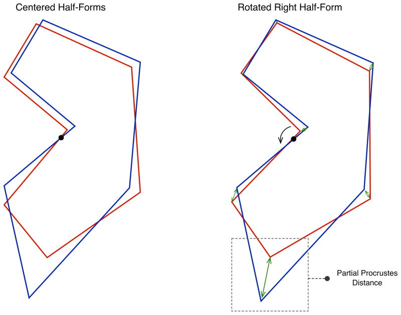
The first maneuver reflects (flips) the right half around its antero-posterior axis, creating a mirror image. This operation makes both halves comparable (Fig. 6). The second maneuver centers both halves on a Cartesian coordinate system. To center the halves we first determine the centroid of each half. Then, we translate both forms until their centroids are on the origin of the Cartesian system (Fig. 6). The third maneuver rotates the right half around its center until it is aligned to the left half (target). Alignment is reached when the distances between corresponding landmarks—of the right and the left halves—are minimal (Fig. 7).
Fig. 6.
LAGER reflects (flips) one of the half-forms, making the half-forms comparable. LAGER also calculates the centroids of each half-form.
Fig. 7.
LAGER translates (moves) both half-forms, setting their centroids at the origin of a Cartesian coordinate system. Next, LAGER rotates one of the half-forms until the sum of the (squared) distances between corresponding landmarks is minimized. Then, LAGER measures the (partial Procrustes) distances between corresponding landmarks.
To quantify the degree of asymmetry of each landmark, we measure the distances between analogous right and left landmarks (Fig. 7). These distances, called ‘partial Procrustes distances’, are (directly) proportional to the degree of asymmetry. Thus, they work well for our estimations.
Unfortunately, Procrustes superimposition is susceptible to the Pinocchio effect7, a phenomenon that occurs when outlier landmarks sway the alignment of a form, magnifying the Procrustes distances of other, less displaced landmarks. Fortunately, we have been able to curtail the Pinocchio effect using a recursive method.
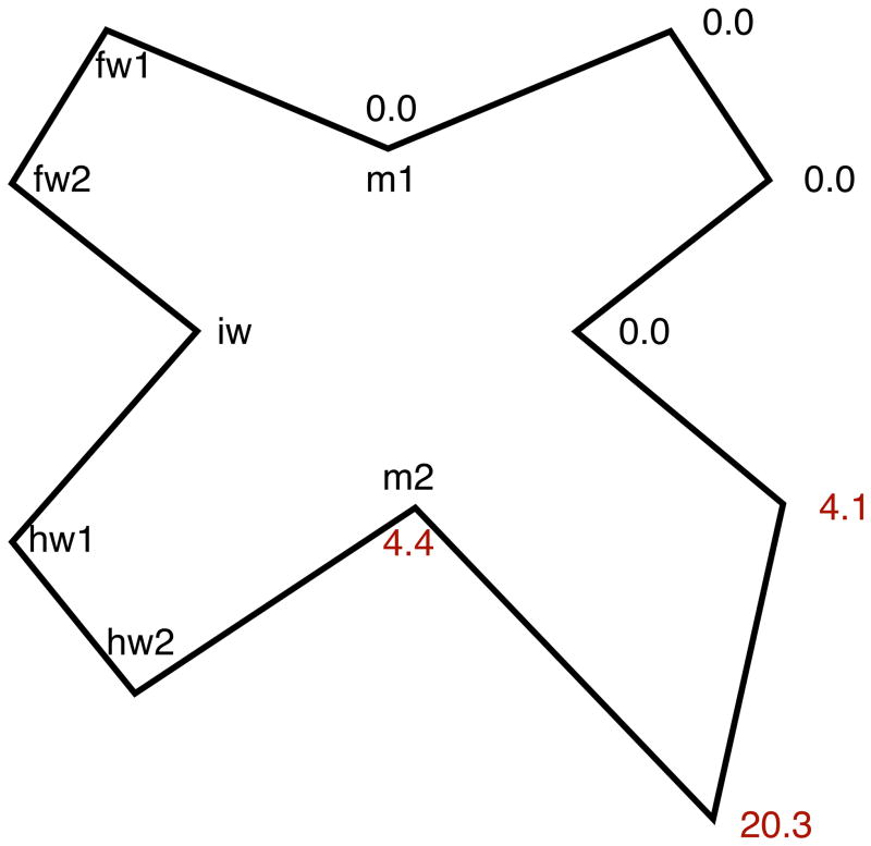
Once LAGER determines the degree of asymmetry of all landmarks, it sorts them from the most asymmetric to the least. Then, it removes the most asymmetric landmarks. Fig. 8 presents the scores for our asymmetric butterfly. Fig. 9 shows how LAGER removed the three asymmetric landmarks, keeping the four symmetric ones.
Fig. 8.
After using a recursive method to control for the Pinocchio effect, LAGER uses the Procrustes distances to scores all landmarks for degree of asymmetry.
Fig. 9.
In the second part of the algorithm, LAGER removes the asymmetric landmarks.
In real patients, however, no landmark is perfectly symmetrical. Instead, we find a gradient of asymmetry that affects the whole head. Thus, selecting the ideal cutoff point for landmark removal is tricky; yet empirical results show that a rule can be developed for the great majority of cases.
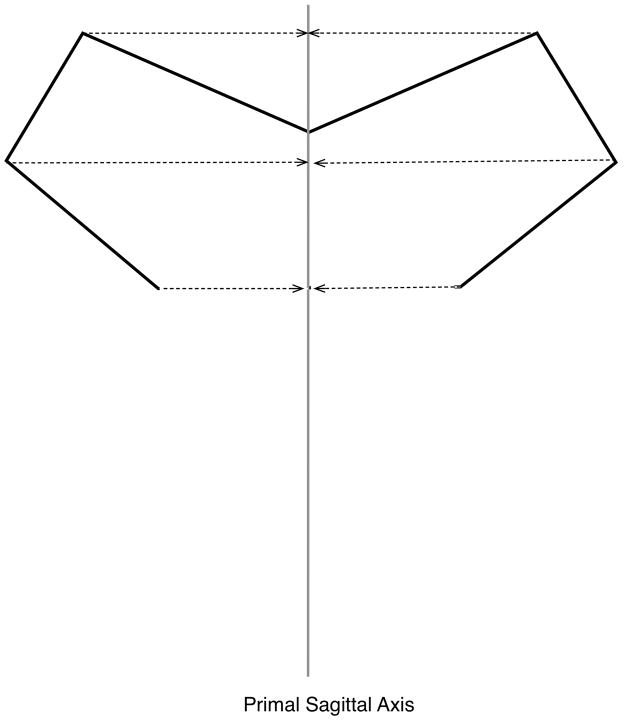
Once all asymmetric landmarks are removed, the third part of the algorithm locates the sagittal plane using a mathematical function that (1) minimizes the distances between the sagittal plane and the remaining midline landmarks; (2) minimizes the distances between the sagittal plane and the midpoints of the residual bilateral landmarks; and (3) minimizes the obliqueness of the lines that connect pairs of bilateral landmarks, as they cross the sagittal plane.
Fig. 10 illustrates how LAGER calculates the primal sagittal axis for our butterfly.
Fig. 10.
In the third part of the algorithm, LAGER estimates the primal sagittal plane by calculating the plane that best-fits the residual landmarks.
Clinical example
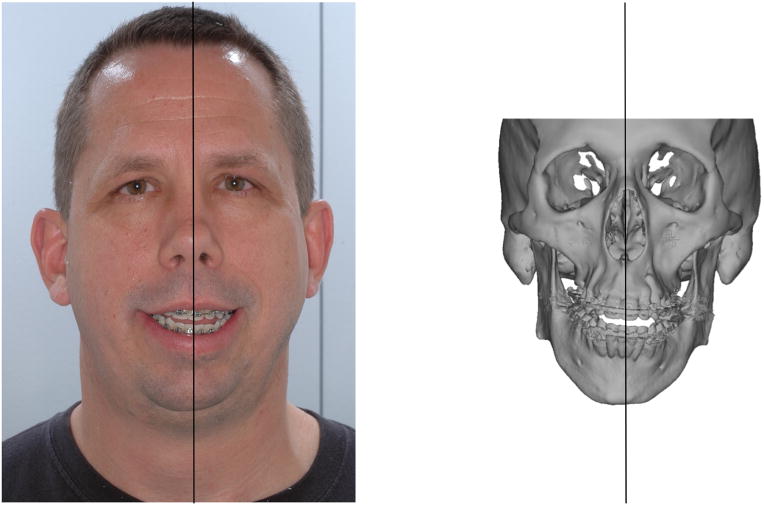
LAGER can estimate the primal sagittal plane for patients with facial asymmetry. Fig. 11 shows the case of a man with significant facial asymmetry. In addition, he also had mandibular retrognathia, an anterior open bite, and severe obstructive sleep apnea. To measure his deformity and to plan his surgery, we estimated the primal frame of reference of his face.
Fig. 11.
Clinical example of a patient with facial asymmetry. On the right, we show how LAGER calculates the primal sagittal plane.
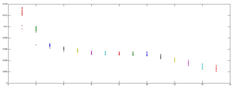
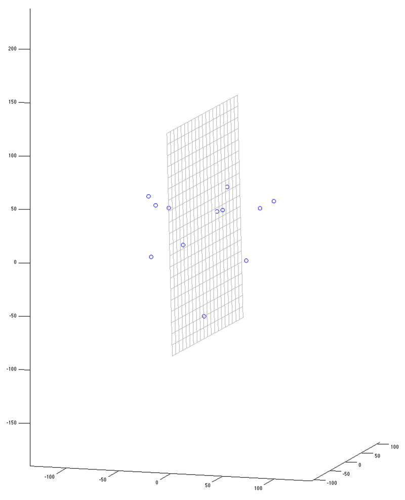
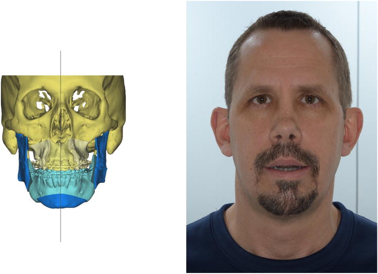
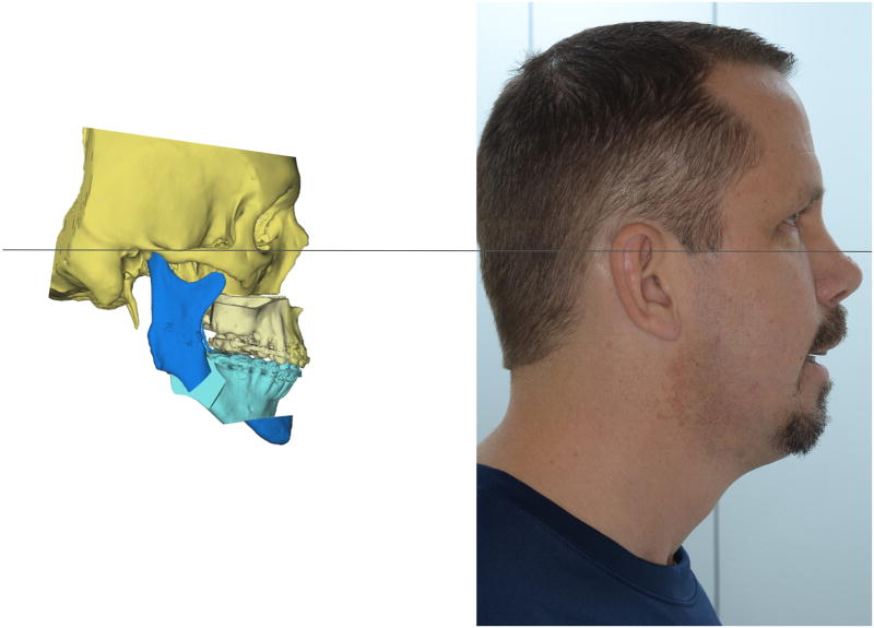
LAGER estimated his primal sagittal plane by first scoring the degree of asymmetry of the different facial landmarks (Fig. 12), then removing the asymmetric landmarks, and finally calculating the best-fit plane for the remaining landmarks (Fig. 13). During planning, we re-established symmetry by balancing the upper and lower jaws across the primal sagittal plane. As can be seen in Figs. 14 and 15, surgery corrected his facial asymmetry.
Fig. 12.
Asymmetry scores for the patient presented in Fig. 11. The landmarks are sorted from left to right, from the most asymmetric to the least.
Fig. 13.
The primal sagittal plane calculated by LAGER. LAGER discards the most asymmetric landmarks before estimating the sagittal plane.
Fig. 14.
On the left, we show the planned operation. On the right, we show the outcome: excellent facial symmetry.
Fig. 15.
On the left, we show the planned operation. On the right, we show the outcome: a straight profile.
Discussion
At first glance, building a sagittal plane for a head seems simple. This simplicity stems from the fact that when we envision this task, we picture doing it on a perfectly symmetrical subject. The face and cranium have two types of landmark: central and lateral. Central landmarks, like nasion, sella, and pogonion, are single. Lateral landmarks, like porion, orbitale, and gonion, are paired. In a symmetrical head, all central landmarks lie on a plane. So we can build the sagittal plane using any combination of three central landmarks. We can also build the sagittal plane using paired lateral landmarks, because each pair of landmarks locates a midpoint that lies on the sagittal plane. Any three midpoints suffice to build the plane. Alternatively, we can build a sagittal plane using a single pair of lateral landmarks, as the sagittal plane crosses the midpoint between corresponding right and left landmarks, staying perpendicular to the line that joins them.
Unfortunately, no human head is perfectly symmetrical1,2, thus building an anatomical frame of reference is complicated. In facial asymmetry—the norm—the middle landmarks are not coplanar. So any combination of three mid landmarks results in a different sagittal plane; the same occurs for bilateral landmarks. We can build hundreds of different sagittal planes, not knowing which one is correct.
So, how can we build a sagittal plane for an asymmetric head? One solution is to use the ‘orthogonal best-fit method’, a method that takes into consideration the universal asymmetry of the head. In this method, a computer algorithm first creates a 3D Cartesian system comprised of three orthogonal planes. Then the algorithm translates and rotates the frame of reference until the sum of distances between the planes and key craniofacial landmarks is minimal. In this approach, the sagittal plane is the plane that best fits all midline landmarks. The axial plane is the plane that best fits all Frankfort landmarks. The coronal plane is the plane that passes through bregma, the point of intersection of the coronal and sagittal sutures.
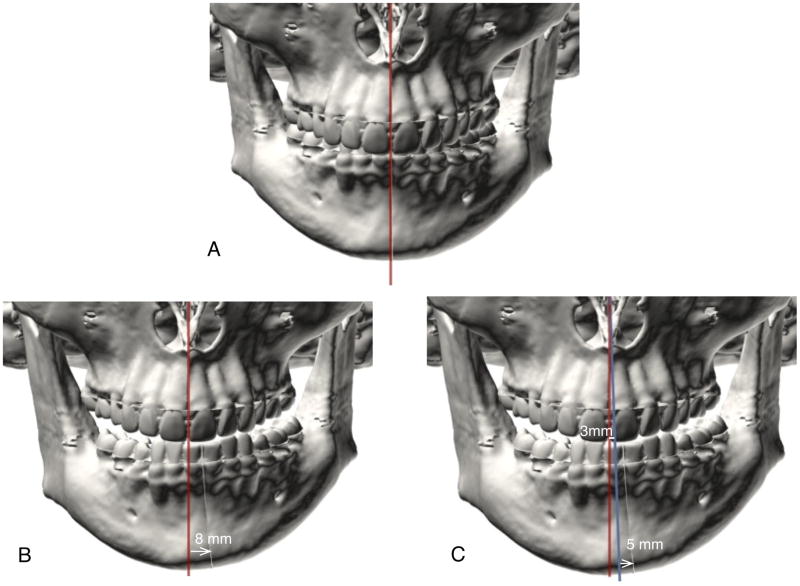
Unfortunately, the orthogonal best-fit method is flawed. Let us explain using an example. Consider an adolescent girl with unilateral condylar hyperplasia. Ten months before we ever see her, her right mandibular condyle begins to grow abnormally, resulting in severe mandibular laterognathia, a deformity that shifts her chin 8 mm to the left. Because the abnormal growth was quick, the rest of her face (including the upper jaw) remains unchanged (Fig. 16).
Fig. 16.
Limitations of the orthogonal best-fit method. (A) A perfectly symmetrical subject. (B) The subject develops unilateral (right) condylar hyperplasia, causing her jaw to shift 8 mm to her left. Because her jaw grows fast, the rest of the face, including the upper jaw, remains unchanged. (C) A computer builds a sagittal plane using the orthogonal best-fit method (blue line). On evaluating the face using this sagittal plane, it will be concluded that the upper jaw is right-deviated by 3 mm and that the chin is left-deviated by 5 mm. We know this is not true; only the lower jaw is deviated.
After seeing the patient for the first time, we order a 3D computed tomography (CT) scan. To analyze the scan, we align it to a standard frame of reference, using the orthogonal best-fit method (Fig. 16). With this method, any cephalometric analysis will show that both her maxilla and her mandible have shifted: the upper jaw to the right by 3 mm, and the lower jaw to the left by 5 mm. We know, however, that only her mandible is affected.
Why did this happen? Why do we get the impression that both jaws are deformed, when only one, the lower one, is? The problem is that the orthogonal best-fit algorithm uses all landmarks in the computations—including the displaced ones. Displaced landmarks skew the sagittal plane.
How can we avoid this problem? In this particular patient, with recent unilateral condylar hyperplasia, we intuitively know which landmarks are displaced. Hence, we can remove them. This tactic eliminates the data that can skew the reference frame, keeping those that do not. However, this ploy rarely works for most patients, because most patients are affected by a gradient of unevenness over the whole craniofacial area. In these patients, it is not obvious which landmarks should be discarded. An extreme example of this problem is a patient with craniofacial microsomia. In order to solve this clinical problem, we first have to answer a fundamental question: What is the ideal plane of symmetry for any patient?
At conception, our genes are programmed to produce perfect facial symmetry, and yet this never occurs. We know this because no individual has perfect facial symmetry1,2. To various degrees, we are all asymmetric; a multitude of stressors influence craniofacial developmental, resulting in asymmetry. Yet to measure facial deformity and to plan its correction there is no better frame of reference than the one a subject would have had if he or she did not have asymmetry. We call it the ‘primal frame of reference’.
How can we determine the sagittal plane in people who already have facial asymmetry? Until now, we have done this by using the NHP4,6. The principle behind its use is that the primal frame of reference of the head can be derived from the NHP. When humans stand erect, looking straight forward, the cardinal directions of their faces (anterior, posterior, superior, inferior, right, and left) are orthogonal to gravity. The axial plane is perpendicular to the gravitational pull. The sagittal and coronal planes are aligned with it. Thus, when the head is in the NHP, constructing a sagittal plane is simple: the sagittal plane is the vertical plane that best divides the face into right and left halves. Since the NHP is unaltered by developing jaw asymmetries, a sagittal plane determined by this method is unaffected by these deformities.
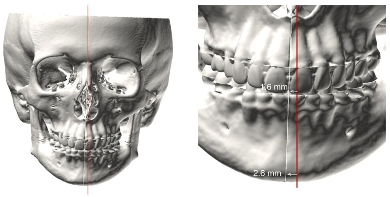
Unfortunately, the NHP method is inconsistent for two reasons. First, some patients have difficulty aligning their heads in the NHP. This is particularly true in children, patients with neuromuscular problems, patients with torticollis, and patients with eye muscle imbalances. Second, even within the same patient, there are temporal variations in the NHP. When we record the NHP for the same patient at different times, we obtain different measurements6. Most of the time, the measurements are close to each other, varying within two degrees. However, even these small variations are problematic. Fig. 17 presents the example of a clinically symmetric patient who rolled his head (around nasion) two degrees during NHP recording. This small error caused the upper incisal midpoint and pogonion to look right-deviated—the upper incisal point by 1.6 mm and pogonion by 2.6 mm—when they were not. These are significant errors.
Fig. 17.
Effect of a small head-tilt during recording of NHP. A symmetric person tilts his head 2 degrees clockwise. The tilt causes his upper dental midpoint and pogonion to look right-deviated, the upper dental midpoint by 1.6 mm and pogonion by 2.6 mm. These are substantial errors.
To solve these problems, our group has developed a new method to define the ‘primal sagittal plane’ of the head, the plane of symmetry a person would have had if he or she had developed symmetrically. This new frame of reference should improve the correctness of our cephalometric measurements and surgical plans.
We estimate the primal sagittal plane using a new algorithm we call LAGER. LAGER works in three steps. In the first step, the algorithm scores all facial landmarks for degree of asymmetry. In the second step, the algorithm removes the most asymmetric landmarks. In the third step, the algorithm calculates the best fitting plane for the remaining landmarks.
Acknowledgments
Funding
This work was partially supported by NIH/NIDCR research grants R42DE016171, R01DE022676, and R01DE021863.
Footnotes
Competing interests
None.
Ethical approval
Not required.
Patient consent
Patient consent was obtained.
Publisher's Disclaimer: This is a PDF file of an unedited manuscript that has been accepted for publication. As a service to our customers we are providing this early version of the manuscript. The manuscript will undergo copyediting, typesetting, and review of the resulting proof before it is published in its final citable form. Please note that during the production process errors may be discovered which could affect the content, and all legal disclaimers that apply to the journal pertain.
References
- 1.Ercan I, Ozdemir ST, Etoz A, Sigirli D, Tubbs RS, Loukas M, Guney I. Facial asymmetry in young healthy subjects evaluated by statistical shape analysis. J Anat. 2008;213:663–669. doi: 10.1111/j.1469-7580.2008.01002.x. [DOI] [PMC free article] [PubMed] [Google Scholar]
- 2.Ferrario VF, Sforza C, Ciusa V, Dellavia C, Tartaglia GM. The effect of sex and age on facial asymmetry in healthy subjects: a cross-sectional study from adolescence to mid-adulthood. J Oral Maxillofac Surg. 2001;59:382–388. doi: 10.1053/joms.2001.21872. [DOI] [PubMed] [Google Scholar]
- 3.Haxby JV, Hoffman EA, Gobbini MI. The distributed human neural system for face perception. Trends Cogn Sci. 2000;4:223–233. doi: 10.1016/s1364-6613(00)01482-0. [DOI] [PubMed] [Google Scholar]
- 4.Schatz EC, Xia JJ, Gateno J, English JD, Teichgraeber JF, Garrett FA. Development of a technique for recording and transferring natural head position in 3 dimensions. J Craniofac Surg. 2010;21:1452–1455. doi: 10.1097/SCS.0b013e3181ebcd0a. [DOI] [PubMed] [Google Scholar]
- 5.Taleb NN. The bed of Procrustes: philosophical and practical aphorisms. New York: Random House; 2010. [Google Scholar]
- 6.Xia JJ, McGrory JK, Gateno J, Teichgraeber JF, Dawson BC, Kennedy KA, Lasky RE, English JD, Kau CH, McGrory KR. A new method to orient 3-dimensional computed tomography models to the natural head position: a clinical feasibility study. J Oral Maxillofac Surg. 2011;69:584–591. doi: 10.1016/j.joms.2010.10.034. [DOI] [PMC free article] [PubMed] [Google Scholar]
- 7.Zelditch ML, Swiderski DL, Sheets HD, Fink WL. Geometric morphometrics for biologists: a primer. San Diego, CA: Elsevier; 2004. pp. 113–119. [Google Scholar]


