Abstract
Energy extraction from waste has attracted much interest nowadays. Herein, a coupled redox fuel cell (CRFC) device using heavy metals, such as copper, as an electron acceptor is assembled to testify the recoveries of both electricity and the precious metal without energy consumption. In this study, a NaBH4-Cu(II) CRFC was employed as an example to retrieve copper from a dilute solution with self-electricity production. The properties of the CRFC have been characterized, and the open circuit voltage was 1.65 V with a maximum power density of 7.2 W m−2 at an initial Cu2+ concentration of 1,600 mg L−1 in the catholyte. 99.9% of the 400 mg L−1 copper was harvested after operation for 24 h, and the product formed on the cathode was identified as elemental copper. The CRFC demonstrated that useful chemicals were recovered and the electricity contained in the chemicals was produced in a self-powered retrieval process.
Heavy metal ions in industrial wastewater pose a potential threat to the living environment and human health due to their accumulation and enrichment in vivo1. Electrochemical approaches are especially effective for heavy metal removal but require a power supply2,3. Currently, instead of energy inputs, net energy extraction from waste has attracted considerable attention4,5,6,7. A metallurgical microbial fuel cell (MFC) is a successful example of copper recovery from wastewater combined with electricity generation8,9,10. However, MFC has some disadvantages, such as long start-up time, stringent working conditions, complicated operation and complex electron transfer mechanisms11. Despite increasing efficiencies in energy conversion and copper treatment due to reactor design and selection of operating parameters9,12, the MFCs can only be operated in neutral or near neutral media.
Fuel cells including solid oxide fuel cell13 are effective electrochemical devices that directly convert the chemical energy in fuels and oxidants into electrical energy14,15, and these fuel cells are a promising power supply. Inspired by fuel cells, we proposed a coupled redox fuel cell (CRFC) device that can successfully harvest energy and treat wastewater16,17. Thermodynamically, the anode redox potential of the CRFC should be lower than the cathode redox potential to ensure spontaneous electrochemical reactions. Using this approach, an interior bias can be produced to transfer the electrons of the anode to the cathode through the external circuit. In this cell, the low redox potential hydrogen-rich substances (or contaminants) in the aqueous solution act as fuels that can be oxidized on the catalytic anode to yield electrons. However, the high redox potential contaminants can function as electron acceptors that can be reduced on the cathode. Therefore, the chemical energy in contaminants can be converted to electrical energy, and some chemicals may be recovered. Therefore, the development of a suitable CRFC for use with certain industrial pollutants is an important area of research that could greatly extend the application of fuel cells in the field of environmental protection (or wastewater treatment), which would be economically beneficial.
Based on this hypothesis, a synthetic wastewater containing Cu2+ was chosen as the cathodic electron acceptor in this study. Copper, which is one of the universal heavy metals, widely exists in various industrial wastewaters from printed circuit board manufacturing as well as the electroplating, mining and metallurgical industries18. Copper is categorized as one of a priority pollutant by the US EPA (U.S. Environmental Protection Agency). However, Cu is a valuable industrial metal, and the recovery of copper from copper containing waste streams is attractive. To construct a high electromotive force to drive the electron transfer in a CRFC, an appropriate fuel is important. Sodium borohydride is a hydrogen-rich fuel used in the development of direct borohydride fuel cells (DBFCs)19,20,21. The BH4− electrocatalytic reaction that occurs on the anode depends on the applied anode catalysts19,22,23. When Ni is used as the anode catalyst, the four-electron anode reaction and standard electrode potentials are shown in equation (1)24,25:
 |
When Cu2+ was employed as an oxidant in the catholyte8, the pH of the catholyte was maintained at 3–4, which favors electroreduction of Cu2+. The final product would be Cu without the production of Cu2O or CuO. With pH control, only one reaction pathway becomes available for cathodic copper reduction, as shown by the following equation:
 |
In the anode chamber, BH4− is oxidized to B(OH)4− with the generation of H2 and electrons. In the cathode chamber, Cu2+ is reduced to Cu. The overall theoretical electromotive force value is 1.987 V.
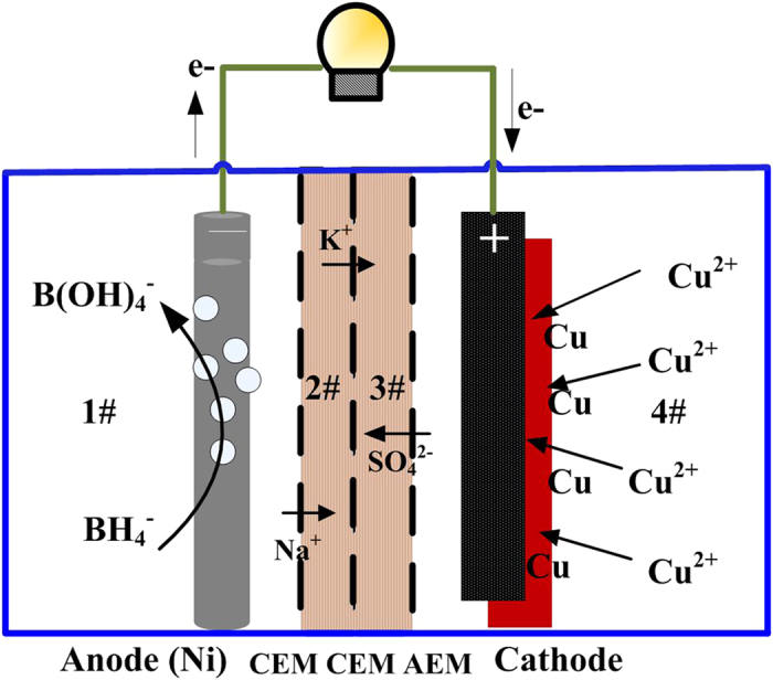
To control the pH in the cathode and prevent Cu2+ from catholyte being simultaneously transferred to the anode chamber, NaBH4 is maintained in an alkaline environment, and OH− is prevented from diffusing into the cathode, which contains a four-chambered NaBH4-Cu CRFC separated by two cation exchange membranes (CEMs) and an anion exchange membrane (AEM), as shown in Fig. 1. When a current is generated by BH4− electrooxidation in the anode chamber, electrons are transferred from the anode to the cathode through the external circuit. These electrons are captured by Cu2+ in the catholyte, which is reduced to Cu0. The positively charged Cu2+ species are prevented from leaving the cathode chamber by the AEM. However, negatively charged SO42− species move from the cathode chamber to the #3 chamber. Double CEMs filled with buffer solutions prevent small amounts of OH− diffusion to the cathode chamber. Positive ions (i.e., Na+ or K+) are required in the buffer to maintain the ion balance. Therefore, positive ions can be transferred from the #2 chamber through the CEM to the #3 chamber. In the anode chamber, H2 is released into solution or the air, resulting in excess positively charged species moving from the #1 chamber to the #2 buffer district. The product of Cu2+ reduction is deposited on the cathode surface along with the generation of electricity. To determine the feasibility of copper recovery, Cu2+ electrochemical deposition at the cathode with simultaneous production of electricity was investigated using a NaBH4-Cu CRFC. In addition, this study focused on characterizing the ability of catalytically oxidative electrodes to remove metal ions and developing a process for the useful recovery of chemicals. The performance of the CRFC was characterized in terms of its power generation, Cu2+ removal efficiency and cathodic efficiency as well as the composition of the deposited products on the cathode under different Cu2+ concentrations.
Figure 1. Schematic diagram of NaBH4-Cu(II) CRFC.
Results and Discussion
Selection of fuel and effect of fuel concentration
To a certain extent, the open circuit voltage (OCV) may account for the fuel cell production capacity14 (i.e., high OCV would produce a higher output voltage). Due to the inevitable polarization loss from a cell, a low OCV would result in a working cell with low efficiency and affect the pollutant removal. To obtain a high OCV, different systems are measured by introducing different compositions of fuels into the anode chamber and a copper ion solution in the cathode chamber. The results are shown in Table 1. When using urea, ethanol, glucose, starch and sodium borohydride as fuels and copper ions as the oxidant, the obtained OCVs are 0.58 V, 0.65 V, 0.78 V, 0.65 V and 1.54 V, respectively, which indicate that all these fuels can be used for copper removal with the production of electricity. In addition, when sodium borohydride was used as the fuel, the OCV of the NaBH4-Cu CRFC was significantly higher than that for Cu CRFCs using other fuels. When 0.2 M NaBH4 and 1 M KOH were used as the fuel along with a cathode copper ion concentration of 400 mg L−1, an open circuit voltage of 1.54 V was produced. Therefore, to obtain a higher output voltage, sodium borohydride was selected as the fuel to investigate copper removal. In addition, KOH was selected as the supporting electrolyte because sodium borohydride is relatively stable in alkaline solutions.
Table 1. OCVs using different fuels in the anolyte.
| Catholyte | Anode catalyst | Fuel components | OCV (V) | Standard emf (V)* |
|---|---|---|---|---|
| 400 mg L−1Cu2+ | 5 mg Ni/cm2 | 0.33 M Urea + 1 M KOH | 0.56 | 1.097 |
| 1 M Ethanol + 1 M KOH | 0.62 | 1.077 | ||
| 0.2 M Glucose + 1 M KOH | 0.75 | 1.577 | ||
| 1% Starch | 0.64 | — | ||
| 0.2 M NaBH4 + 1 M KOH | 1.54 | 1.987 |
*Standard electromotive force (emf): Standard potential of the Cu2+/Cu redox pair minus the standard potential of the fuel redox pair in the anode.
Figure 2 shows the current evolution as a function of time using different initial NaBH4 levels. The OCV increased from 1.54 V to 1.67 V as NaBH4 increased from 0.2 M to 0.8 M. The initial current density for all three levels was 1.11, 1.13 and 1.22 A m−2 after adding an external load of 1000 Ω. A maximum difference of only 0.11 A m−2 was observed in the beginning. Then, the maximum difference (difference between the current densities at high concentration and low concentration) increased to 0.39 A m−2 at 16 h and further increased to 0.72 A m−2 at 20 h. This result indicates that excess fuel can maintain a high current output. However, in the NaBH4 fuel cell, high concentrations (1.5–2.4 M) of sodium borohydride decreased the electron transfer number and increased fuel hydrolysis, which can result in low fuel efficiency25. Therefore, a low NaBH4 concentration of 0.2–0.8 M was used as the fuel in the NaBH4-Cu(II) CRFC.
Figure 2. Current evolution as a function of time for the NaBH4-Cu(II) CRFC.
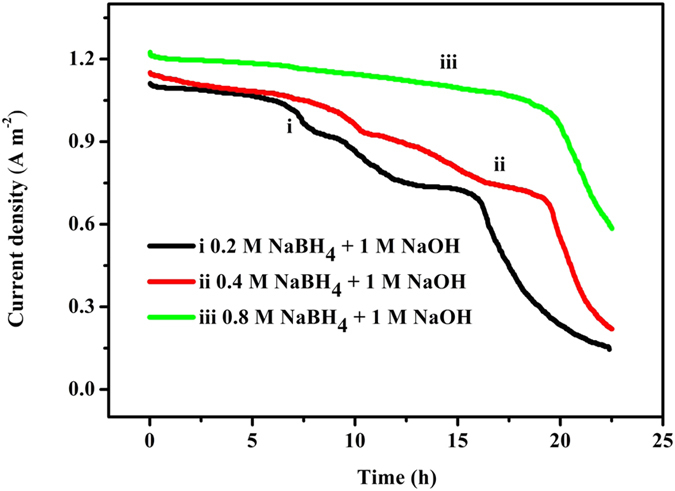
Anolyte: 0.2 M NaBH4 (i, black), 0.4 M NaBH4 (ii, red) and 0.8 M NaBH4 (iii, green) in 1 M NaOH; Catholyte: 800 mg L−1 Cu2+.
In addition, the current output of the three groups with different fuel concentrations exhibited a similar pattern. Above a certain value, the current output was stable after the external load of 1000 Ω followed by a turning point that appeared near 15 h, 18 h and 20 h, for the three levels. Then, the current decreased sharply in nearly a straight line. Near these turning points, copper in the catholyte is still detected, which indicates that the fuel was nearly consumed at these turning points.
Effect of initial Cu2+ concentration
The results in Fig. 3 indicate that the NaBH4-Cu(II) CRFC exhibits a considerable electrical output for various initial Cu2+ concentrations in the catholyte. When 1,600 mg L−1 Cu2+ was employed as the electron acceptors, the CRFC reached an OCV of 1.65 V and an initial current density of 1.11 A m−2 with a constant external load of 1000 Ω. As the initial Cu2+ concentration decreased to 800 mg L−1, an OCV of 1.59 V was achieved, and the corresponding initial current density decreased to 1.05 A m−2. A further decrease in the initial Cu2+ concentration to 400 mg L−1 resulted in an OCV and initial current density of 1.54 V and 0.98 A m−2, respectively.
Figure 3. Current evolution as a function of time for the NaBH4-Cu(II) CRFC.
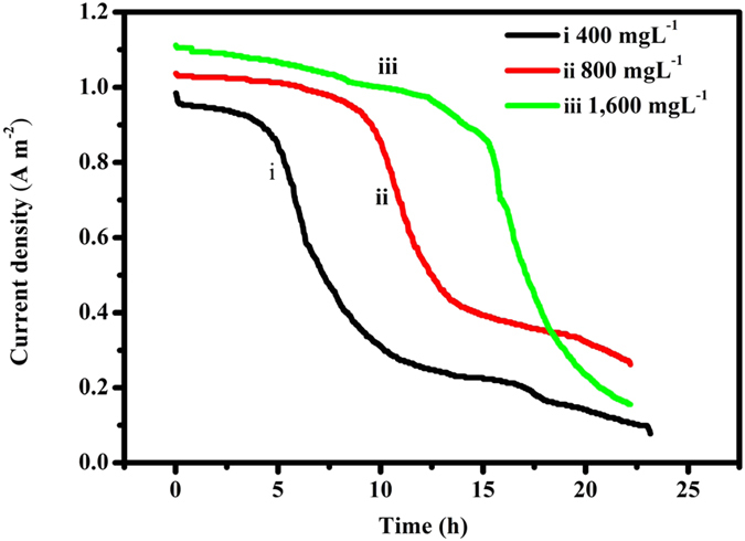
1,600 mg L−1 Cu2+ (iii, green), 800 mg L−1 Cu2+ (ii, red) and 400 mg L−1 Cu2+ (i, black); Anolyte: 0.2 M NaBH4 in 1 M NaOH.
The current production at all of initial copper levels as a function of time is shown in Fig. 3. Interestingly, the current density curves exhibited the same trend and reached a plateau at the beginning and then decreased quickly. Notably, the plateau became larger as the initial Cu2+ concentration increased. When the Cu2+ concentration was increased to 1,600 mg L−1, the plateau lasted approximately 15 h at a high level. Then, the current density decreased gradually in the following 10 h after the 15-h plateau. This result was reasonable because a higher copper concentration (1,600 mg L−1) can provide more electron acceptors that allow the cell to run longer at a high current density compared to a lower copper level (400 mg L−1). It was also noticed that the current density from 1,600 mg L−1 Cu2+ deteriorated to lower than that from 800 mg L−1 Cu2+ after 18 hrs running in Fig. 3. The reason for this may be that more fuels needed to be consumed for 1,600 mg L−1 Cu2+ and so that the Pmax dropped faster than that for 800 mg L−1 Cu2+ against 0.2 M NaBH4.
The voltage under a load of 1000 Ω with an initial 800 mg/L Cu2+ was 720 mV, which was higher than that of the microbial desalination cell (568 mV)12. This result may be due to two factors. First, the theoretical anodic potential was −1.35 V ([OH−] = 1 M, [BH4−] = 2.0 M) using NaBH4 as the fuel in this study, which was much more negative than −0.296 V (pH = 7, [CH3COO3−] = [HCO3−] = 0.05 M) for the acetate fuel used in their work12. Secondly, the internal resistance of the NaBH4-Cu(II) CRFC with an initial Cu2+ concentration of 800 mg L−1 was only 18.7 Ω, which was significantly less than that of the MFC (41.6 Ω)12. A low internal resistance indicates low voltage losses and a high output voltage.
Figure 4 shows the polarization curves for the maximum electricity generation using the procedure in the methods section. An increase in the initial Cu2+ concentration from 100 mg L−1 to 1,600 mg L−1 results in an increase in the maximum power density (Pmax) by a factor of 2.4 from 3.0 W m−2 at 0.82 V, 3.2 A m−2 to 7.2 W m−2 at 0.92 V, 8.5 A m−2. The Pmax data indicates that when higher initial Cu2+ concentrations were used, a higher power density at a higher current density was obtained.
Figure 4.
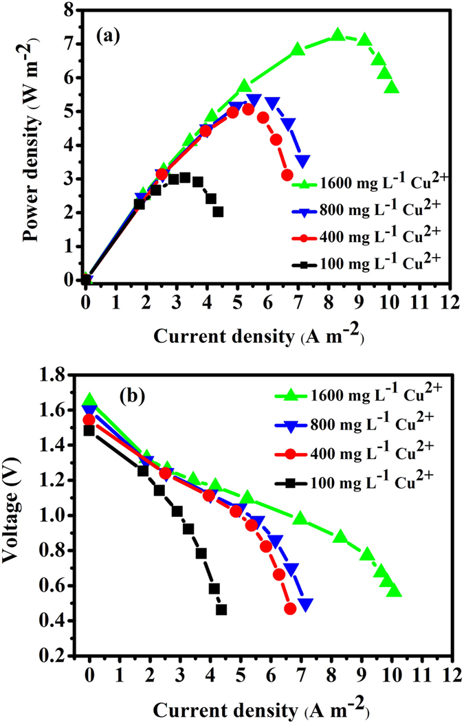
Power density (a) and polarization (b) curves for the NaBH4-Cu(II) CRFC. 1,600 mg L−1 Cu2+ ((▲), 800 mg L−1 Cu2+ (▼), 400 mg L−1 Cu2+ (●) and 100 mg L−1 Cu2+ (■)); Anolyte: 0.2 M NaBH4 in 1 M NaOH.
Effect of temperature
The results in Fig. 5 demonstrate the effect of temperature on the voltage and power density. As shown in Fig. 5(a), the power density and voltage output increase as the temperature increased. This result is due to two factors. First, a high temperature can accelerate the electrochemical reaction and reduce the activation resistance. Secondly, an increase in the temperature is favorable for mass transfer and decreases concentration polarization. As shown in Fig. 5(b), a Pmax of 0.26 W m−2 at a current density of 0.5 A m−2 at 15 °C was observed. When the operation temperature increased from 15 °C to 25 °C, an increase in Pmax by a factor 2.1 was observed (i.e., from 0.5 W m−2 to 1.05 W m−2). A further increase in temperature to 45 °C results in a Pmax of 1.33 W m−2, which is a factor of 1.3 higher than 1.05 W m−2 at 25 °C. In addition, a high temperature would accelerate fuel hydrolysis and reduce fuel efficiency. Therefore, in this study, the operation temperature was determined to be 25 °C.
Figure 5.
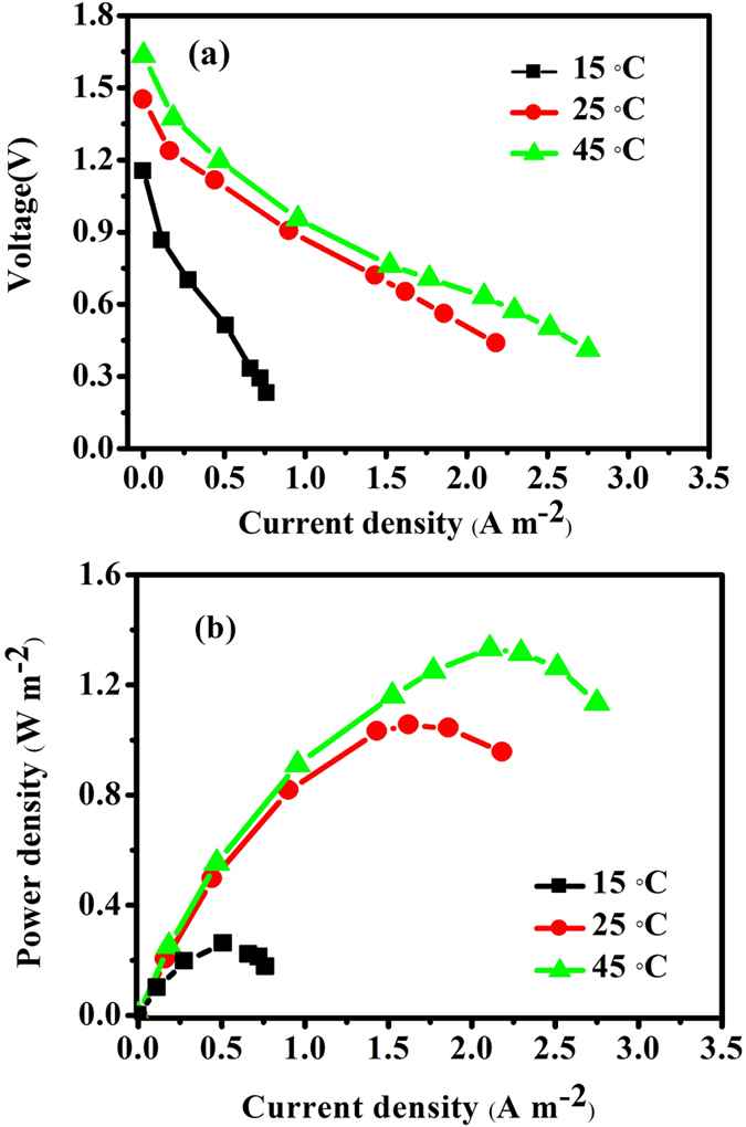
Polarization curve (a) and power profiles (b) at different temperatures. (15 °C (■), 25 °C (●), 45 °C (▲) and fixing the anolyte at 0. 2 M NaBH4 in 1 M NaOH and catholyte at 400 mg L−1 Cu2+ in 0.5 M HAC-NaAC (pH = 3.5).
Copper removal
Table 2 shows the copper removal percent (RCu) and cathodic efficiency (ηcath) of the NaBH4-Cu(II) CRFC at three initial copper levels. The copper removal rate was 75.08 ± 0.3% at 16 h for an initial copper concentration of 400 mg L−1, and an increase in the time to 24 h can result in an increase in the removal percentage to 99.9 ± 0.4%. In addition, the cathodic efficiency was ~100%. However, no more than 100% was observed at 24 h when the initial copper concentration was increased to 1,600 mg L−1, which indicates that more electrons were recorded as current being produced than those consumed by copper electroreduction. Therefore, another oxidant was present in the catholyte and consumed a portion of the electrons released from the anode. Oxygen is most likely present in the catholyte, which would result in the production of a background current due to oxygen reduction. This phenomenon easily occurred at a low copper concentration due to the standard potential of oxygen (1.23 V vs SHE) being significantly greater than the copper reduction potential (0.337 V vs SHE). Nevertheless, when a high copper concentration was present in the catholyte, this background current can be ignored because the trace oxygen amount was much smaller than the copper concentration.
Table 2. Cu2+ removal rate (RCu) and cathodic efficiency (ηcath) under different initial copper concentrations.
| Cu(II) C0(mgL−1) | 16 h |
24 h |
||
|---|---|---|---|---|
| Rcu(%) | ηcath(%) | Rcu(%) | ηcath(%) | |
| 400 | 75.08 ± 0.3 | 90.6 ± 0.4 | 99.9 ± 0.4 | 108.2 ± 0.3 |
| 800 | 65.3 ± 0.4 | 92.3 ± 0.3 | 85.6 ± 0.6 | 99.3 ± 0.4 |
| 1,600 | 34.6 ± 0.5 | 79.6 ± 0.6 | 46.2 ± 0.3 | 92.6 ± 0.5 |
Product of the process
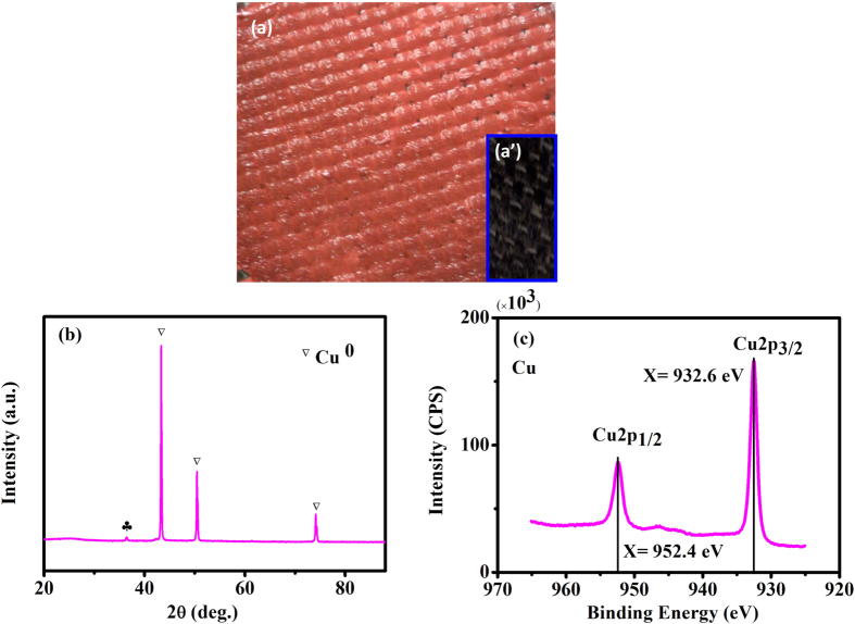
The oxidation state of the deposited Cu species has been identified. A brick red product (see Fig. 6(a)) was formed on the cathode. XRD and XPS measurements were employed to determine the composition and oxidation states of the reduction species. The diffraction peaks at 2θ values of approximately 43.3°, 50.4° and 74.1° in the XRD (Fig. 6(b)) can be indexed to copper. Figure 6(c) shows the typical XPS spectra of the Cu species. For all of the deposited species, the binding energies of Cu 2p3/2 and Cu 2p1/2 were 932.4 eV and 952.2 eV, respectively. The Cu 2p3/2 peak can be used to determine the oxidation states of the Cu species. The position of the main peak of Cu 2p3/2 at approximately 932.6 eV corresponded to elemental Cu. However, no Cu(II) and Cu(I) were detected. Cu(II) deposition in the catholyte bulk was not observed due to the low pH of the bulk solution (pH <3.5). Therefore, copper can be removed from the aqueous solution using this NaBH4-Cu(II) CRFC system.
Figure 6. Cathodic reduction of copper.
Photo of copper deposited on a carbon cloth electrode (a) compared to the initial electrode (a’), XRD (b), XPS (c).
Feature and ability of the CRFC
Self-driven copper retrieval from solutions containing Cu2+ combined with power harvesting makes this new approach suitable for copper recovery. The efficiencies are comparable to the results achieved with other electrochemical copper recovery methods, such as electrowinning27,28. In contrast to the electrowinning requiring power supply, which consumed 3.3 kWh kg−1 Cu28, the CRFC produced power, which was equivalent to an energy production of 9.3 kWh Kg−1 of Cu (data derived from 800 mg L−1 Cu2+ as the catholyte). This produced energy may allow this process to be applied more widely.
Another feature of the CRFC is its ability to generate electricity. The comparison between CRFC and MFCs will certainly be unavoidable even though the mechanism of electricity generation from the two processes is completely different. For example, by applying an initial 800 mg L−1 Cu2+ concentration and an external resistance of 1000 Ω, the initial current density in the CRFC is ca. 1.05 A m−2, which is 3 times higher than the peak current density of the MFC (<0.3 A m−2) using ions bridge composed of membranes and salt solutions12 as the separator. At the same initial 800 mg L−1 Cu2+concentration, NaBH4-Cu CRFC produce a Pmax of 5.4 W m−2, which is 24, 22 and 7 times the results reported by An et al. (0.226 W m−2)12, Tao et al. (ca. 0.25 W m−3)10 and Ter Heijne et al. (0.8 W m−2)8, respectively. Cheng et al.9 and Motos et al.26 substantially improved the power density and achieved ca. 2.0 W m−2, which is still less. More than 99.9% removal of 400 mg L−1 Cu2+ was achieved in this study in 24 h. In contrast, 80 h was needed in the MFC study12, and 30 h was required by the CRFC to achieve 99.6% removal of 800 mg L−1 Cu2+. In addition, 168 h was need for 99.88% removal of 1000 mg L−1 in a MFC8 because it is time-consuming and laborious to transmit electrons from the interior of microbial cells to the surface of electrodes5,11. Overall, the new assembly consisting of a coupled redox fuel cell using copper as an electron acceptor combines the production of electricity with in situ retrieval of copper.
Conclusions
Considerable recoveries of both electricity and copper metal without energy consumption can be successfully achieved in a coupled redox fuel cell (CRFC) device. Hydrogen used as a fuel in sodium borohydride in an alkaline medium in this system would result in a high OCV. The generation of electricity will increase as the initial Cu2+ concentration increases. An increase from 0.2 M to 0.8 M in the initial NaBH4 concentration favors current production from 1.11 to 1.22 A m−2 at the initial stage, and from 0.70 to 1.08 A m−2 at 16 h. Increase in temperature to 45 °C results in a Pmax of 1.33 W m−2, which is significantly higher than Pmax of 0.26 W m−2 at 15 °C. Elemental copper was uniformly formed on the cathode to provide a unique electrowinning process for copper recovery that was self-powered.
Methods
NaBH4-Cu(II) CRFC assembly
The NaBH4-Cu CRFC reactor contained four chambers named #1, #2, #3 and #4. Liquid was not pumped through the chambers but was standing still. The copper sulfate solution in 0.5 M HAC-NaAC (pH = 3.5) was fed as the electron acceptor into the cathode chamber (#4). 0.2 M NaBH4 in a 1 M NaOH solution was used as the fuel in the anode chamber (#1) except fuel effect experiments. In the NaBH4-Cu CRFC, the pH values in the four chambers were maintained using a buffer solution (i.e., 7 (#2), 3.5 (#3) and 3.5 (#4)) and an alkaline solution (#1). #4 is separated from the other three parts by one AEM. One CEM is next to the anode chamber, which separate #1 from #2. This chamber functions as a selective bridge, permitting the passage of positively charged sodium ions but not negatively charged hydroxyl ions. A CEM is used to separate the two sections (#2 and #3) and further consolidates the role of the previous CEM. The #2 and #3 chambers were filled with buffer solution containing 0.5 M PBS (KH2PO4-Na2HPO4, pH 7) and 0.5 M HAC-NaAC (pH = 3.5).
Ni/C catalysts were prepared according to a previously published method29. Then, Ni/C was mixed with deionized water (0.83 μL/mg Ni/C), 5% Nafion dispersion (6.67 μL/mg Ni/C) and isopropyl alcohol (3.33 μL/mg Ni/C). After ultrasonic dispersion for 30 min, this mixture was painted on a carbon fiber cloth (Tansu, Jinlin, China) with a loading of 5 mg Ni/cm−2 29. The resulting cloth was used as the anode in the NaBH4-KOH solution after it was dried in air for 24 h. The same area carbon cloth was used as the cathode.
Analyses and calculations
Concentrations of the Cu(II) samples at the interval time were measured using the AAS (Atomic absorption spectroscopy) method. The composition and oxidation states of the cathodic product was measured by XRD (X-ray diffraction) using Shimadzu XRD-6000 with a Cu-Kα radiation source and XPS (X-ray photoelectron spectroscopy) using ESCALAB_250Xi with an Al-Kα excitation source, respectively. A data acquisition system (PISO-813, ICP DAS Co., Ltd) was employed to record the voltage (U) every minute. Polarization curves, current and power density were obtained according to a previously published protocol16. The Cu (II) removal efficiency (Rcu) was calculated based on the Cu (II) concentrations at time t and the initial time using Rcu = (C0-Ct)/C0. The amount of copper reduction was calculated based on the difference between Cu (II) reduction obtained in the control experiment (C0-Ccon) and that obtained under a closed circuit (C0-Ct). This value was divided by the electricity production by integrating the current over time, which is defined as the cathodic efficiency (ηcath) and calculated as follows:
 |
where ηcath is the cathodic efficiency (%), t is the operation time (h), Rex is the constant external load (Rex = 1000 Ω) under a closed circuit, Ct, C0 is the Cu (II ) concentration (mg L−1) at time t and the initial time, respectively, Ccon is the Cu (II ) concentration (mg L−1)) at time t under the control experiment, V is the volume of the catholyte (20 mL), b is the number electrons of per mol Cu (II) to copper (b = 2 mol e−/mol Cu (II)) and F is the Faraday constant (96485 C mol−1).
Additional Information
How to cite this article: Zhang, H.-M. et al. Assembly of coupled redox fuel cells using copper as electron acceptors to generate power and its in-situ retrieval. Sci. Rep. 6, 21059; doi: 10.1038/srep21059 (2016).
Acknowledgments
The authors are grateful for the financial support of NSFC (Grant No. 21473158, 21173188, 51468016) and Post Doctoral Fund of China (No. 2015M581941).
Footnotes
Author Contributions H.Z. proposed the concept. Z.W., B.L. directed the research. H.Z. and W.X. designed the experiments. H.Z., W.X. and G.L. carried out the experiments. H.Z. wrote the main manuscript text and prepared figures. Z.L. Gave his valuable comments on the manuscript and the amendment. All of the authors reviewed the manuscript.
References
- Wang N. X. et al. Effects of Microcystin-Lr on the Metal Bioaccumulation and Toxicity in Chlamydomonas Reinhardtii. Water Res., 46, 369–377 (2012). [DOI] [PubMed] [Google Scholar]
- Peng G. Q., Tian G. M., Liu J. Z., Bao Q. B. & Zang L. Removal of Heavy Metals from Sewage Sludge with a Combination of Bioleaching and Electrokinetic Remediation Technology. Desalination, 271, 100–104 (2011). [Google Scholar]
- Akbal F. & Camci S. Copper, Chromium and Nickel Removal from Metal Plating Wastewater by Electrocoagulation. Desalination, 269, 214–222 (2011). [Google Scholar]
- McCarty P. L., Bae J. & Kim J. Domestic Wastewater Treatment as a Net Energy Producer-Can This Be Achieved? Environ. Sci. Technol, 45, 7100–7106 (2011). [DOI] [PubMed] [Google Scholar]
- Logan B. E. & Rabaey K. Conversion of Wastes into Bioelectricity and Chemicals by Using Microbial Electrochemical Technologies. Science, 337, 686–690 (2012). [DOI] [PubMed] [Google Scholar]
- Sun P. Z. et al. Realizing Synchronous Energy Harvesting and Ion Separation with Graphene Oxide Membranes. Sci. Rep. 4, 5528 (2014) [DOI] [PMC free article] [PubMed] [Google Scholar]
- Wang Y.-Z. et al. Hydrodynamics of an Electrochemical Membrane Bioreactor. Sci. Rep. 5, 10387 (2015) [DOI] [PMC free article] [PubMed] [Google Scholar]
- Ter Heijne A. et al. Copper Recovery Combined with Electricity Production in a Microbial Fuel Cell. Environ. Sci. Technol, 44, 4376–4381 (2010). [DOI] [PubMed] [Google Scholar]
- Cheng S. A., Wang B. S. & Wang Y. H. Increasing Efficiencies of Microbial Fuel Cells for Collaborative Treatment of Copper and Organic Wastewater by Designing Reactor and Selecting Operating Parameters. Bioresource Technol, 147, 332–337 (2013). [DOI] [PubMed] [Google Scholar]
- Tao H. C. et al. Removal of Copper from Aqueous Solution by Electrodeposition in Cathode Chamber of Microbial Fuel Cell. J. Hazard. Mater. 189, 186–192 (2011). [DOI] [PubMed] [Google Scholar]
- Logan B. E. et al. Microbial Fuel Cells: Methodology and Technology. Environ Sci Technol, 40, 5181–5192 (2006). [DOI] [PubMed] [Google Scholar]
- An Z. Y., Zhang H. C., Wen Q. X., Chen Z. G. & Du M. A. Desalination Combined with Copper(Ii) Removal in a Novel Microbial Desalination Cell. Desalination, 346, 115–121 (2014). [Google Scholar]
- Kannan R., Singh K., Gill S., Furstenhaupt T. & Thangadurai V., Chemically Stable Proton Conducting Doped BaCeO3 -No More Fear to SOFC Wastes. Sci. Rep. 3, 2138 (2013). [DOI] [PMC free article] [PubMed] [Google Scholar]
- Winter M. & Brodd R. J. What Are Batteries, Fuel Cells, and Supercapacitors? Chem. Rev. 104, 4245–4269 (2004). [DOI] [PubMed] [Google Scholar]
- An L. & Zhao T. S. An Alkaline Direct Ethanol Fuel Cell with a Cation Exchange Membrane. Energy Environ. Sci. 4, 2213–2217 (2011). [Google Scholar]
- Zhang H. M., Xu W., Wu Z. C., Zhou M. H. & Jin T. Removal of Cr(Vi) with Cogeneration of Electricity by an Alkaline Fuel Cell Reactor. J. Phys. Chem. C, 117, 14479–14484 (2013). [Google Scholar]
- Yu B. B., Zhang H. M., Xu W., Li G. & Wu Z. C. Remediation of Chromium-Slag Leakage with Electricity Cogeneration Via a Urea-Cr(Vi) Cell. Sci. Rep. 4, 6 (2014). [DOI] [PMC free article] [PubMed] [Google Scholar]
- Da’na E. & Sayari A. Effect of Regeneration Conditions on the Cyclic Performance of Amine-Modified Sba-15 for Removal of Copper from Aqueous Solutions: Composite Surface Design Methodology. Desalination 277, 54–60 (2011). [Google Scholar]
- Finkelstein D. A. et al. Self-Poisoning During Bh4- Oxidation at Pt and Au, and in Situ Poison Removal Procedures for Bh4- Fuel Cells. J. Phys. Chem. C, 117, 1571–1581 (2013). [Google Scholar]
- Arevalo R. L., Escano M. C. S. & Kasai H. Computational Mechanistic Study of Borohydride Electrochemical Oxidation on Au3ni(111). J. Phys. Chem. C, 117, 3818–3825 (2013). [Google Scholar]
- Yi L. H. et al. High Activity of Au-Cu/C Electrocatalyst as Anodic Catalyst for Direct Borohydride-Hydrogen Peroxide Fuel Cell. Int. J. Hydrogen energy, 36, 15775–15782 (2011). [Google Scholar]
- Wang K. L., Lu J. T. & Zhuang L. A Current-Decomposition Study of the Borohydride Oxidation Reaction at Ni Electrodes. J. Phys. Chem. C, 111, 7456–7462 (2007). [Google Scholar]
- Escano M. C. S., Gyenge E., Arevalo R. L. & Kasai H. Reactivity Descriptors for Borohydride Interaction with Metal Surfaces. J. Phys. Chem. C, 115, 19883–19889 (2011). [Google Scholar]
- Li Z. P., Liu B. H., Arai K. & Suda S. Development of the Direct Borohydride Fuel Cell. J. Alloy. Compd. 404, 648–652 (2005). [Google Scholar]
- Liu B. H., Li Z. P. & Suda S. Electrocatalysts for the Anodic Oxidation of Borohydrides. Electrochim. Acta 49, 3097–3105 (2004). [Google Scholar]
- Motos P. R. et al. High rate copper and energy recovery in microbial fuel cells, Frontiers in Microbiology 6, 5271–8 (2015) [DOI] [PMC free article] [PubMed] [Google Scholar]
- Rodchanarowan A., Sarswat P. K., Bhide R. & Free M. Production of copper from minerals through controlled andsustainable electrochemistry, Electrochimica Acta. 140, 447–456 (2014). [Google Scholar]
- Britto-Costa P. H., Pereira-Filho E. R. & Ruotolo L. A. M. Copper electrowinning using a pulsed bed three-dimensional electrode, Hydrometallurgy 144–145 15–22 (2014) [Google Scholar]
- Xu W., Zhang H. M., Li G. & Wu Z. C. Nickel-Cobalt Bimetallic Anode Catalysts for Direct Urea Fuel Cell. Sci. Rep. 4, 6 (2014). [DOI] [PMC free article] [PubMed] [Google Scholar]


