Abstract
Distribution of the electrical field is very important to activate muscle and nerve cells properly. One therapeutic method to treat Recurrent Laryngeal Neuropathy (RLN) in horses can be performed by Functional Electrical Stimulation (FES). Current method to optimize the stimulation effect is to use implanted quadripolar electrodes to the musculus cricoarythenoideus dorsalis (CAD) and testing electrode configuration until best possible optimum is reached. For better understanding and finding of maximum possible activation of CAD a simulation model of the actual entire setting is currently in development. Therefore the geometric model is built from CT-data of a dissected larynx containing the quadripolar electrodes as well as fiducials for later data registration. The geometric model is the basis for a finite difference method containing of voxels with corresponding electrical conductivity of the different types of tissue due to threshold segmentation of the CT-data. Model validation can be done by the measurement of the 3D electrical potential distribution of a larynx positioned in an electrolytic tray. Finally, measured and calculated results have to be compared as well as further investigated. Preliminary results show, that changes of electrode as well as conductivity configuration leads to significant different voltage distributions and can be well presented by equipotential lines superimposed CT-slices – a Matlab graphical user interface visualizes the results in freely selectable slices of the 3D geometry. Voltage distribution along theoretically estimated fiber paths could be calculated as well as visualized. For further calculation of nerve or denervated muscle fiber activation and its optimization, real fiber paths have to be defined and referenced to the potential- and the CT-data.
Key Words: Modelling, simulation, equine larynx, Functional Electrical Stimulation, denervation
Long Term Denervated Muscle Fibers (DM) and its Functional Electrical Stimulation (FES) need specific stimulation parameter as well as electrode configuration.1-4 Often, in the case of Recurrent Laryngeal Neuropathy (RLN), active nerve fibers are remaining. Thus it has to be investigated both, nerve and direct muscle stimulation of musculus cricoarythenoides dorsalis (CAD). Therefore two coupled simulation models are needed. One is used for the calculation of the electrical field due to FES and the other for calculating the activation of either nerve or muscle structures.1-4
For calculation of the 3D electrical field a finite element or finite difference model is often used,2,4 where the basic simulation geometry is built by segmented CT-data.1 Region properties, like electrical conductivity,5-7 have to be adjusted to build a proper simulation model able to calculate reality-near behavior. Validation of the model can be done by electrical field measurements using an electrolytic tray. These results have to be registered to the CT-data by markers (e.g. fiducials and/or geometry of the measurement set-up), which can be detected during field measurement as well as in the CT-data.8,9 Activation of a nerve or a muscle fiber can be calculated by the use of Hodgkin-Huxley-type models.10 Therefore the voltage distribution along the fiber path has to be known in order to calculate the so called “activating function”.11 From the quasi-static 3D-field model this voltage distribution can be taken as a basis for calculation of dynamic fiber activation due to different pulse shapes as well as stimulation patterns.11
In order to optimize FES in CAD of equine larynx a mathematical model for the calculation of the electrical field has to be built. Optimization means that lowest electrical energy is needed, which is related to the specific electrical field distribution in target regions. These electrical field distributions, due to different tissue properties and geometry, can be adjusted by electrode position and geometry as well as boundary conditions like surrounding air or electrolytic fluid, respectively.
Materials and Methods
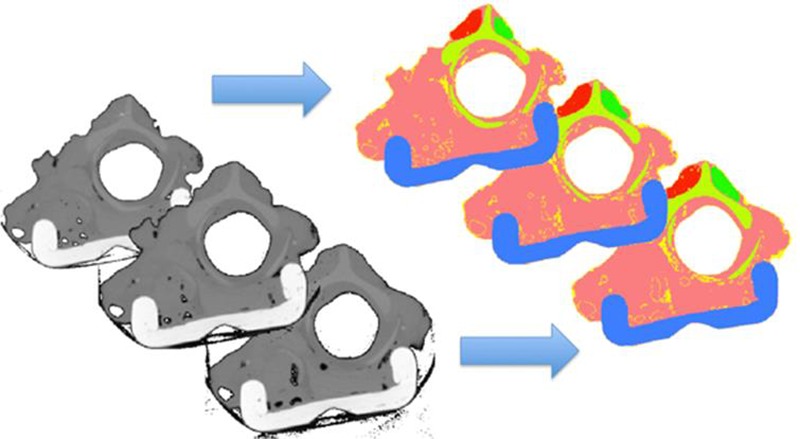
For the calculation of a 3D electrical field in equine larynx, a corresponding 3D geometry is needed and can be built on the basis of the CT-data and the corresponding electrical conductivity of the different types of tissue due to threshold segmentation (Fig. 1). Additionally, boundary conditions for the entire simulation system have to be defined by consideration of the currently performed measurements of the 3D electrical field by the use of a customized measurements system9 with the larynx embedded in an electrolytic tray. FES is applied via two implanted quadripolar electrodes offering the possibility of different electrode configurations (Fig. 2). In order to complete the definition of the boundary conditions, the electrode positions of these implanted electrodes (Osypka K5P4) have to be determined from CT-data. In order to be able to calculate the electrical field a corresponding numerical mathematic model has to be built up. Therefore a proper discretization is needed. Based on the geometric information from the CT-data, which is provided in up to 700 slices as well as 512x512 pixels per slice, a so-called voxel discretization has been chosen. One voxel is of size 0.484x0.484x0.4mm3, which corresponds to the equal spaced pixel size Δx = Δy = 0.484mm and the constant slice distance of Δz = 0.4mm. The equation system is based on the 3D Poisson’s equation
| (equ. 1) |
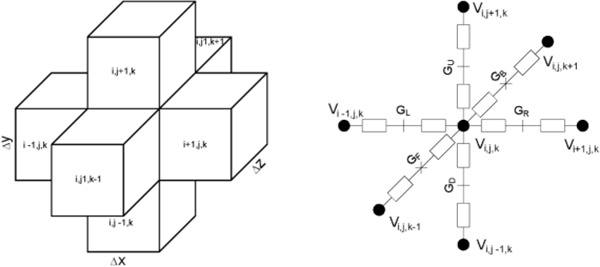
where Δ is the Laplace operator, φ is the electrical potential and f is mostly a real function. For conductive media the Poisson’s equation derives to the right part of equation 1; where s is the Nabla operator, g is the conductivity of the tissue (Tab. 1, corresponding to each voxel), u is the voltage distribution and i is the current flowing over defined boundaries of the system (e.g. electrode positions). Finally, each center voxel has 6 neighbors connected via the represented conductivity of the tissue (Fig. 3).
Fig. 1:

Raw CT-slices (left) and segmented slices (right) with colored regions of different tissue: red and green, CAD-muscle; pink, muscle; light-green, cartilage; yellow, fat; blue, tissue-carrier.
Fig. 2:

Schematic of quadripolar electrodes with different possible configurations between electrode A and B: red, anode; blue, cathode.
Tab. 1:
Conductivities of tissue (adapted from5-7) as well as air and surrounding electrolytic solution.
| Material | Conductivity (S/m) |
|---|---|
| Muscle | 0.4 |
| Fat | 0.03 |
| Cartilage | 0.016 |
| Bone | 0.016 |
| Electrolytic Solution | 1.679 |
| Air | 0 |
| Tissue Carrier | 0 |
Fig. 3:

Schematic of a center voxel with its 6 neighbors (left) and its corresponding equivalent circuit (right), where the centers of the voxels are interconnected by the conductivity G of the involved tissue; i, j and k are indices for the equally spaced distances Δx, Δy and Δz in directions of x, y and z.
Based on the described voxel model and corresponding to equation 1 a system of linear equation – one equation per center voxel – can be built and finally solved by an iterative method. Due to electrode positioning and optimum boundary setting, the above-described dataset of 700x512x512 voxels can be reduced to 200 slices with lower number of pixels per slice and leads to a system of up to 50x106 equations:
| (equ. 2) |
However, equation 2 is a symmetric, large and highly sparse system and can be solved by finding a minimum norm residual solution of u. Using Matlab R2013 / 64bit, installed on Windows 7 / 64bit and an appropriate hardware (Intel i7, 2.4GHz, 24GB RAM), it takes approx. 4-5 hours to calculate.
In order to show the 3D solution of equation 2, using equipotential-lines overlaid to the raw CT-slices or the threshold-segmented and finally colored data the voltage distribution can be shown. Additionally the voltage distribution along an arbitrary path can be calculated like along a nerve fiber or a denervated muscle fiber, respectively. Finally the activation function could be calculated to estimate weather the nerve or muscle fiber is potentially activated by FES or not.
Results
Optimization of FES in CAD of equine larynx can be investigated by the means of modeling and simulation. Therefor the main focus lies on the calculation of the electrical field distribution according to the applied electrical current via a pair of electrodes. Finally, the voltage distribution along a fiber path can give the right information weather a nerve or muscle fiber is electrically activated or not. The current study shows the modeling and simulation based on a dissected equine larynx, which is embedded in an electrolytic tray for performing electrical field measurements. Therefor the tissue is surrounded by electrolytic fluid in contrary to the natural situation, where the tissue is surrounded by air. For that reason both cases – for surrounding air and electrolytic fluid – have to be calculated and compared.
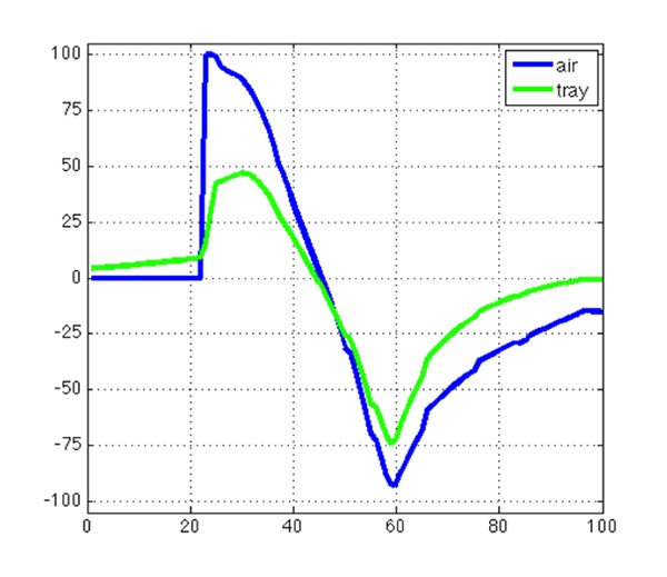
Fig. 5 shows that the voltage distribution for the case of surrounding air is up to double of amplitude than for the case of electrolytic fluid. This means, that for the experiments embedded in the electrolytic tray higher amplitudes in FES are necessary to electrically activate nerve or muscle fibers properly. Nevertheless, modeling and simulation of the experiments in the electrolytic tray is very important to have the possibility of validating the calculated results by comparison to the field measurements.
Fig. 5:

Voltage distribution along a theoretical fiber path; blue: result from the larynx-model with surrounding air, green: result from the larynx-model embedded in the electrolytic tray with surrounding electrolytic fluid
Currently, the comparison of the calculated and the measured electrical field is not sufficient enough coming from distortion of tissue caused by CT-measurements of the dissected larynx outside of the electrolytic tray. This means, that the modeled geometry from CT-data is different to the field measurement situation. To cope that problem future CT-measurements will be performed by moving the entire electrolytic tray more or less unchanged to the CT. A further advantage of this future method will be that the measured and the calculated electrical field can be referenced by the use of the edges of the electrolytic tray and will substitute the inaccurate positioning of the fiducials. A feasibility study has to show how to implement above considerations in detail and will give further information for future improvements.
To estimate the electrical activation of nerve and muscle fibers by applying FES the anatomical details have to be investigated. This means that position and direction of the fibers have to be determined and registered to the CT-data, which gives the voltage distribution along this path. Out of this voltage distribution, the so-called “activating function”, 11 can be calculated to provide the necessary input for the model of nerve or muscle fibers, respectively. Finally, depending on the type and size of fibers, the activation corresponding to pulse shapes of the applied electrical current can be calculated for optimizing the entire FES process.
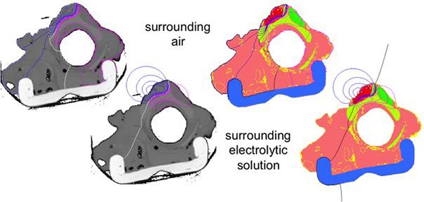
For the entire simulation process of calculating the electrical field, a Matlab graphical user interface has been developed. This user interface supports to set up the geometric model, to place and configure the electrodes, to set the proper conductivities of the different regions of the tissue or the surrounding material and finally to show the results of the calculated field as equipotential lines superimposed to the raw or segmented CT-slices (Fig. 4).
Fig. 4:

Calculated electrical field shown by equipotential lines for anodic (purple) and cathodic (blue) field as well as reference line (left: white, right: black); top: results for surrounding air, bottom: results for surrounding electrolytic fluid, left: superimposed to raw CT-slices, right: superimposed to segmented slices.
One question to answer is the difference of the distribution of the electrical field using the equine larynx embedded in an electrolytic tray or just for the case of surrounding air, respectively. In Fig. 4 it can clearly be seen, that the equipotential lines show different shapes. Of course, this is very obvious and for the case of surrounding air no equipotential lines are drawn in the area out of the tissue. This is caused by the isolating behavior of the air and means, that the entire electrical field is distributed in the area of conductive tissue. For the case of the larynx embedded in electrolytic fluid, equipotential lines are drawn in the area outside of the tissue as well. This is caused by the relatively high conductive behavior of the electrolytic fluid (Tab. 1) and means, that the electrical field is also distributed to the area of the fluid. For that reason, there should be differences in strength of the electrical field as well as in electrically activating the target tissue like nerve or denervated muscle fibers by means of FES. Comparing equipotential line is maybe not that satisfying as expected, because it is very difficult to quantify differences properly. For that reason it is more interesting to investigate a so called “fiber path”, which can be represented by a straight line drawn through the regions of interest. The potential distribution along such a fiber path can be shown in a diagram as voltage over path length (Fig. 5). Representative for diverse possible locations and directions of a fiber path, one theoretically chosen nerve or muscle fiber path is defined by a straight line close to anode and cathode, respectively. Voltage distribution along this line (Fig. 5) is shown for the case of larynx embedded in electrolytic tray as well as the case of surrounding air. Voltage levels are amplitude normalized by the maximum amplitude of the voltage distribution for the case of surrounding air. It can clearly be seen, that the amplitude for the case of surrounding air is up to double of amplitude for the case of the larynx embedded in the electrolytic fluid.
Discussion
Optimization of FES in CAD of equine larynx can be investigated by the means of modeling and simulation. Therefor the main focus lies on the calculation of the electrical field distribution according to the applied electrical current via a pair of electrodes. Finally, the voltage distribution along a fiber path can give the right information weather a nerve or muscle fiber is electrically activated or not. The current study shows the modeling and simulation based on a dissected equine larynx, which is embedded in an electrolytic tray for performing electrical field measurements. Therefor the tissue is surrounded by electrolytic fluid in contrary to the natural situation, where the tissue is surrounded by air. For that reason both cases – for surrounding air and electrolytic fluid – have to be calculated and compared.
Fig. 5 shows that the voltage distribution for the case of surrounding air is up to double of amplitude than for the case of electrolytic fluid. This means, that for the experiments embedded in the electrolytic tray higher amplitudes in FES are necessary to electrically activate nerve or muscle fibers properly. Nevertheless, modeling and simulation of the experiments in the electrolytic tray is very important to have the possibility of validating the calculated results by comparison to the field measurements.
Currently, the comparison of the calculated and the measured electrical field is not sufficient enough coming from distortion of tissue caused by CT-measurements of the dissected larynx outside of the electrolytic tray. This means, that the modeled geometry from CT-data is different to the field measurement situation. To cope that problem future CT-measurements will be performed by moving the entire electrolytic tray more or less unchanged to the CT. A further advantage of this future method will be that the measured and the calculated electrical field can be referenced by the use of the edges of the electrolytic tray and will substitute the inaccurate positioning of the fiducials. A feasibility study has to show how to implement above considerations in detail and will give further information for future improvements.
To estimate the electrical activation of nerve and muscle fibers by applying FES the anatomical details have to be investigated. This means that position and direction of the fibers have to be determined and registered to the CT-data, which gives the voltage distribution along this path. Out of this voltage distribution, the so-called “activating function” can be calculated to provide the necessary input for the model of nerve or muscle fibers, respectively. Finally, depending on the type and size of fibers, the activation corresponding to pulse shapes of the applied electrical current can be calculated for optimizing the entire FES process.
Acknowledgements
This paper could not be written to its fullest without the support of Sven Otto from the Institute of Veterinary Anatomy, University of Leipzig, Germany who provided the perfused equine larynx as well as the CT-data, Paolo Gargiulo from the Department of Science, Landspitali University Hospital, Reykjavik, Island who did CT-data segmentation, the research group of Klaus Peter Koch from the Technical Department, University of Applied Sciences Trier, Germany who designed and built the field measurement device and finally to the company Med-El, Emerging Applications, Innsbruck, Austria for giving the financial support to this project. We’d like to thank all of them very much!
References
- 1.Martinek J, Reichel M, Rattay F, Mayr W. Analysis of calculated electrical activation of denervated muscle fibres in the human thigh. Artif Organs, 2005;29:444-7. [DOI] [PubMed] [Google Scholar]
- 2.Martinek J, Stickler Y, Reichel M, Rattay F. Electrical stimulation of denervated skeletal muscles: a modeling study of transcutaneous stimulation. 2006; Presentation: Proceedings Symposium on Spinal Cord Motor Control, Ljubljana, Slovenia; 07.09.2006-09.09.2006; in: From denervated muscles to neurocontrol of locomotion, 89. [Google Scholar]
- 3.Reichel M, Mayr W, Rattay F, Computer simulation of field distribution and excitation of denervated muscle fibers caused by surface electrodes. Artif Organs, 1999;23:453-6. [DOI] [PubMed] [Google Scholar]
- 4.Reichel M, Martinek J, Mayr W, Rattay F. Functional electrical stimulation of denervated skeletal muscle fibers in 3D human thigh - modeling and simulation. In: Proceedings of the 8-th Vienna International Workshop on Functional Electrostimulation, 2004; pp. 44–7. [Google Scholar]
- 5.Faes T, van der Meij, de Munck J, Heethaar R. The electric resistivity of human tissues (100 Hz–10 MHz): a meta-analysis of review studies. Physiological Measurement, 1999; 20: R1-R10. [DOI] [PubMed] [Google Scholar]
- 6.Gabriel C, Gabriel S, Corthout E. The dielectric properties of biological tissues: I. Literature survey. Physics in Medicine and Biology, 1996; 41: 2231-49. [DOI] [PubMed] [Google Scholar]
- 7.Miklavčič D, Pavšelj N, Hart F. 2006. Electric Properties of Tissues. Wiley Encyclopedia of Biomedical Engineering [Google Scholar]
- 8.Gargiulo P. 3D Modelling and monitoring of denervated muscle under Functional Electrical Stimulation treatment and associated bone structural changes. Eur J Trans Myol 2013;23:31-94. [Google Scholar]
- 9.Martini P, Cercone M, Cheetham J, Koch KP. Experimental electrical field distribution measurements in a perfused ex vivo model. Biomed Tech 2012;57:870-3. [Google Scholar]
- 10.Hodgkin AL, Huxley AF. A quantitative description of membrane current and its application to conduction and excitation in nerve, J Phsyiol 1952;117:500-44. [DOI] [PMC free article] [PubMed] [Google Scholar]
- 11.Rattay F. Electric nerve stimulation (theory, experiments and applications), Springer-Verlag Wien New York, 1990. [Google Scholar]


