Abstract
The project “Finger Rehabilitation” aims to design a neuroprosthesis with integrated electronics. The neuroprosthesis should enable spinal cord injured people, with injury at cervical vertebrae level, to increase finger mobility and activity with the use of functional electrical stimulation. The equipment is based on several integrated factors. The user has to be independent from any external help and has to be able to put it on, control the electrical stimulation and remove it by himself. The neuroprosthesis has to be both flexible and stable for the electrodes to remain firmly on the skin. In this part of the project, new electrodes which do not get stuck on the skin are described. The electrodes are small and have low impedance. A sleeve, made from glass fibres, is also described. The electrode matrices are integrated in the sleeve. The neuroprosthesis fits a patient with spinal cord injury at C5-C6. In this work, a novel electrode concept integrated in a glass fibre sleeve is tested on its ability for use in an “independent user” neuroprosthesis for finger movement rehabilitation.
Key Words: augmentation of impaired finger functions, electrode concept, feasibility study, neuroprosthesis, SCI at C5-C6
The range of reported global prevalence of spinal cord injury (SCI) is 236 to 4187 per million. In 2007 there were between 133 and 226 thousand incident cases globally and the median value for new incidences in Western Europe is 16 per million.1 SCI people loose motoric function and the result is a lifelong dependency on caregivers.2 Functional electrical stimulation (FES) has been used for rehabilitation since the beginning of 1960’. FES is a method used to activate paralyzed muscles with the purpose of generating or improving lost muscle control.3 FES has been found effective in generating functions and restoring grasp in C5-C7 complete SCI people. The central paresis of muscles that need to be stimulated has to be prevailing and there should not be a major degree of motor neuron or nerve root damage in the stimulated muscles.4,5 FES systems for upper extremity have only been applied successfully to patients with functional capacity in shoulders and elbows. Patients with motor level lesion at C4 need modules for restoration of the shoulder-, elbow-, and hand functions. In contrast, a patient with lesion at C5 only requires a module for restoration of the hand functions, as shoulder and elbow functions are nearly completely preserved.2
Former trials of finger rehabilitation equipment have been made. “FreeHand System“ was put on market in 1997,5,6 Ness Handmaster was developed in Ra’anana, Israel,7-9 and the Bionic Glove was designed by the University of Alberta, Canada.7,9 None of them is in use by wider number of tetraplegic patients. The implanted systems are too expensive, require surgery and complicated external equipment. They all have in common that the increased functionality of the fingers is low and does not encurage daily use.
Until now, one Icelandic patient has been tested with FES in the “Finger Rehabilitation” project. The patient has SCI at C6-C7 and has almost no mobility in the finger muscles, a slight mobility in the wrist but shoulder and elbow function is almost preserved. Former prototype of the neuroprosthesis was designed as an open splint made of soft cast with a Velcro, used to close the neuroprosthesis around the arm. Oval shaped electrodes of size 4cm x 6,4cm (Axelgaard, PALS Platinum) were included at specific locations for stimulation of the finger muscles. Four stimulation channels were used where each channel consisted of single cathode and anode self-adhesive electrodes. These channels were used to generate a flexion and extension in finger muscles and flexion and extension in the thumb muscle.3,10 The right hand was stimulated from the year 2009 until 2012 and CT pictures have been taken over the period. Analysis of the tissue density with a special software, MIMCS, have suggested an increase in muscle tissue density in both arms.11
Existing stimulation technology requires search for the optimal electrode placements for each subject since the stimulation sites vary between individuals. Research has been done on the application of electrode matrix to locate optimal stimulation sites for specific hand functions of SCI patients and to elicit finger movements. The electrode matrices allow relocation of simulating sites without moving the electrodes. 5,10 To improve existing technology, the new electrode matrix application will use current division where each electrode in the matrix can have specific current. This includes: 1) the possibility for autonomic search for the best electrode placements and 2) electrical stimulation pattern that produces specific movement for every finger muscle and every individual. The overall concept is a neuroprosthesis formed as a sleeve, made of glass fiber, with integrated electrode matrices. New electrodes have been designed which are not self-adhesive. The main goal of the project is that the SCI user is able to put the prosthesis on, take it off, and control the electrical stimulation without external assistance. It should improve existing technology in a way that the electrodes do not get stuck on the skin and it is easier for the patient to put on and remove the equipment.
The purpose of the current work is to test the feasibility of a novel electrode concept, integrated in a neuroprosthesis, made of glass fibers, for augmentation of impaired finger movements. The prosthesis has been tested in vitro and with one patient with SCI at C6-C7.
Materials and Methods
A prototype of a neuroprosthesis has been designed. A sleeve made of glass fiber with integrated novel electrode matrices will be described.
The Overall System
The overall control of the system is illustrated in figure 1.3 The electrode matrices, integrated in the sleeve, are controlled manually with a switchboard where stimulation pulses are provided with an external stimulator. A microcomputer to control the current in each electrode with both hardware and software components is under construction. Furthermore, the user will control the stimulation with a tablet computer through a graphical user interface which is under construction.
Fig 1.
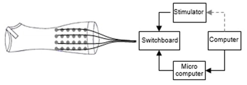
The user controls the current with a personal tablet computer. The external stimulator elicits the current which is divided to the electrodes via switchboard which is further controlled with a microcomputer.
Novel Electrodes
The self adhesive electrodes which are usually used for FES are considered inappropriate for this neuroprosthesis because they cannot be easily removed by the tetraplegic user. Eight electrode matrices are integrated in the sleeve, replacing single electrodes used for each channel in former stimulation concept. The electrodes designed are made of stainless steel, wires, and sponges. They do not get stuck on the skin. The connecting wire is fastened to the metal and the 0,9% NaCl saturated sponge is fixed to the steel and wire. The sponge is exchangeable. Each electrode in the matrix has diameter of 12 mm. It has been shown that larger surface area of the electrode reduces electrical resistance between metal and ion solution. To increase the surface area of the electrode, narrow slots are cut in the metal.
It is important to reach the best possible conductance of the electrodes. The resistance between each of the electrode components, which is the wire, metal and the sponge, has to be minimized. Adequate connection between the wire and the metal is established with a resistance of only few ohms. It is more challenging to minimize the resistance on the interface between the metal and the skin or the ion solution. The sponge is saturated with isotonic solution (0,9% NaCl) to reduce the resistance. The characteristic of a good sponge is that it has large water capacity. The sponge chosen for the electrodes has good water storage capability which decreases resistance.
These electrodes are integrated in the neuroprosthesis. To reduce crosstalk between electrodes, the metal piece and the sponge are embedded in silicon just leaving the contact sponge surface exposed. With the silicone around each electrode, a hermetic chamber is made for the sponge and solution preventing the solution leakage and electrical current flow on the skin surface.
Impedance Measurements
The impedance of the electrodes of different surface areas and shapes were measured. The purpose was to look for an electrode pair with low impedance. All measurements were performed in a room with temperature of 23°C and 40% humidity. Five electrode pairs having different forms were measured: A square (4 cm2), a circle (ca 4 cm2), a small circle (ca 1.1 cm2), a small circle with six slots and a small circle with seven slots.
A model for an electrode pair in isotonic solution is shown in figure 2. The total impedance, Ztot of the electrode model is calculated in Eq. 1.
Fig 2.
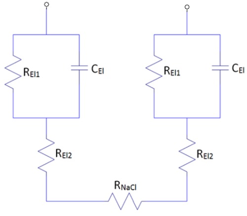
A model for an electrode pair in an isotonic solution (0,9% NaCl). One electrode is on each side with REl1, REl2 and CEl1. RNaCl is the resistance of the solution that simulates the resistance of the skin
 |
Eq. 1 |
The measurement setup and electrodes are shown in figure 3. A photograph of the measurement setup is shown in figure 4. The electrode pairs where placed in a small bath filled = with 0.9% NaCl solution. The key parameters of the bath and solution are shown in table 1. The lower part of the metal and the inside of the slots was covered with the solution. One of the electrodes was connected to a 10 Ω resistor and a sinusoidal current was passed through the electrodes from the oscillator. The current intensity and the phase angle, α between the current and the voltage was measured and used for calculations of the electrode impedance (see equations 2-4).
Fig 3.
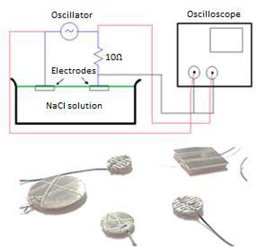
The upper figure shows the measurement setup. The electrodes are placed on the surface of the water so the sponge and the lower half of the metal is saturated with ion solution. The lower figure shows the electrodes which are measured
Fig 4.
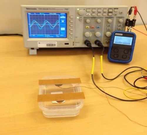
A photograph of the measurement setup. An electrode pair in an isotonic solution (0,9% NaCl), an oscillator and an oscilloscope
Table 1.
The parameters for the bath and NaCl solution. RNaCl is an exemplified resistance of the solution used for the calculations of the electrode model.
| Breadth (cm) | 8.70 | RNacl [MIN] (Ω) | 16.91 |
| Length (cm) | 5.10 | RNacl [MAX] (Ω) | 1593.75 |
| Deapth (cm) | 2.60 | RNacl [AV] (Ω) | 805.33 |
| Amax (cm2) | 22.62 | RNACL(Ω) | 100.00 |
| Amin (cm2) | 0.24 | QNacl (Ω) | 75.00 |
Equations 2-4 describe the total impedance and the real- and imaginary parts of the impedance respectively,12:
| Eq: 2 |
| 3 |
 |
4 |
Explanations:
| α | = | Phase angle between the current and the voltage |
| u | = | Voltage |
| i | = | Current |
| RNaCl | = | Exemplified solution impedance |
Measured and calculated values of the impedance were compared. The resistance and capacitance values for the calculated model were modified for each of the electrodes to fit the measurement results.
Measurements of electrode impedance for the different electrode forms were performed at frequency ranging from 0-100Hz. The measurements for different forms were compared for a sinusoidal current with peak value of 2mA, 10mA, and 20mA due to non-linear dependency on current amplitude.
At last, measurements were performed to see how the impedance of the electrodes would change with time. Electrode pairs with silicone cover were compared to electrode pairs without silicone cover. Both electrode pairs were placed on a conducting rubber. Sinusoidal current was applied and the same method was used, as described above, to calculate the impedance of the electrodes.
The Sleeve
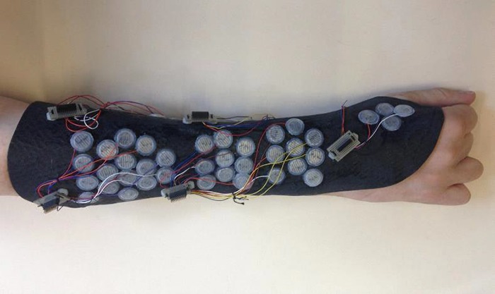
The newest mechanical design of the neuroprosthesis is a sleeve made of glass- and carbon fibers covered with leather on the side that touches the skin. A plaster model of one SCI subject has been made and is used to form the neuroprosthesis. Each sleeve is different and should fit each individual hand properly. First, a layer of leather, which makes good contact with the skin, is stretched over the plaster model. Then the glass- and carbon fibers are stretched over the whole model. The whole model is then put into an oven where the sleeve is heated up to 100°C and the glass- and carbon fibers stiffen. Holes are made where the electrodes will be placed. The fibers are cut out to form the desired shape of the sleeve. At last the electrodes are put in the holes. The thickness of the glass- and carbon fiber layer defines the stiffness of the sleeve wall. This thickness has to be chosen so that the user can penetrate into the sleeve side wards. At the same time the sleeve has to press the electrodes with an adequate force to the skin to ensure conductivity. A photograph of a sleeve, designed for a specific subject, with integrated electrodes and connections is shown in figure 5.
Fig 5.
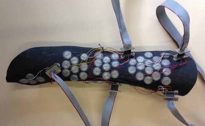
A photograph of the sleeve with integrated electrodes and connections.
When designing the sleeve, the primary point of view is that SCI patients who have no mobility in the fingers can use it themselves without any external help. The glass fibers are cut through the lateral side of the sleeve. The cut has to be wide enough for the arm to come through but not too wide so that the electrodes have good contact to the skin. The sleeve contains eight electrode matrices. Each matrix contains up to 16 electrodes. The electrode matrices are put in place over the muscles that are intended to be stimulated. That restricts the form of the sleeve. This means that the form has to be designed with respect to the placements of the electrodes.
Testing of the Sleeve with Electrode Matrices
The sleeve with integrated electrode matrices was connected to a manually controlled switching box, see figure 6. The sleeve with integrated electrodes was fitted on one subject. The subject got instructions on how to place the sleeve without any external assistance.
Fig 6.
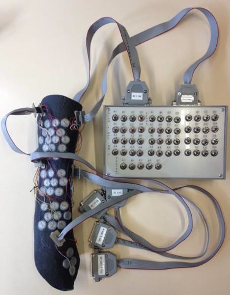
A photograph of the sleeve and electrodes connected to a manually controlled switchbox.
Results
The results of the measurements are shown in figures 7-12.
Fig 7.
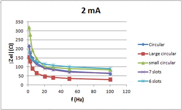
The electrode impedance for 2 mA vs. frequency
Fig 8.
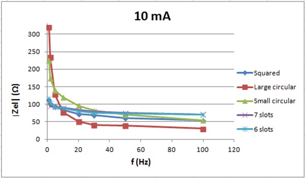
The electrode impedance for 10 mA vs. frequency
Fig 9.
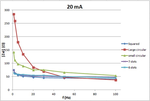
The electrode impedance for 20 mA vs. frequency.
Fig 10.
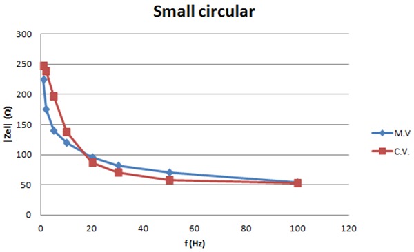
The graph shows the measured and calculated values of the impedance for 10 mA vs. frequency for the small electrodes with no slots.
Fig 11.
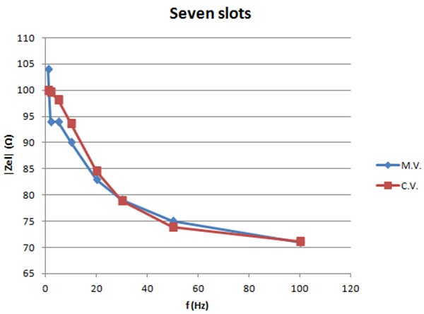
The graph shows the measured and calculated values of the impedance for 10mA vs. frequency for the small electrodes with seven slots.
Fig 12.
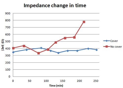
The graph shows the impedance of an electrode pair covered with silicone and the impedance of an electrode pair without a silicone cover. Both pairs are placed on a conducting rubber and stimulation current applied.
Figure 7 shows the electrode impedance for 2 mA current intensity vs. frequency. The electrode pair with 7 slots has lower impedance then the small circular with no slots. The pair with 6 slots has about the same impedance as the one with no slots for frequency above 15 Hz but lower impedance below 15Hz. Figure 8 shows the electrode impedance for 10 mA. For frequencies below 30 Hz, small circular electrodes with 6 and 7 slots have lower impedance then electrodes without slots. For frequencies higher than 30 Hz, small circular electrodes without slots have lower impedance then electrodes with slots. For 20 mA, see figure 9, the impedance of the six and seven slots electrodes is lower than the impedance of the small circular electrodes for all frequencies.
Figures 10-11 show the measured and calculated values of the impedance of the small electrodes with no slots and the small electrodes with seven slots for 10mA current intensity. Calculations are based on the model in figure 2. Values can be found for the components in the model that match the calculated curves with the measured ones as shown in the graphs. Table 1 lists these component values. The graphs show that the model fits well the measured values and can be used for calculations.
Figure 12 shows the impedance for an electrode pair with a silicone cover and an electrode pair without a silicone cover, respectively. The graph shows that the impedance remains the same for 250 minutes when electrodes are covered with silicone while after ca. 100 minutes the impedance starts rising and approaches infinity for the electrodes with no cover. The results show that the silicone covers keep the solution in the sponge. The electrodes can be used for a longer time with the covers then without them.
The testing of the equipment shows that the sleeve fits the subject’s arm in a normal position. Furthermore the subject could easily put the sleeve on and take it off without any external help. The sleeve does unfortunately not adapt to the form of a rotated arm, leaving the lateral electrodes with little or no connection to the skin. Figure 13 shows a photograph of the sleeve fitted on a patient hand.
Fig 13.
A photograph of the sleeve fitted on the patient harm.
Discussion
The main goal of this part of the finger rehabilitation project is that the patient is able to use it in every way by himself. He should be able to put it on, control the stimulation and take it off at the end of use. The main methods to achieve this goal are described in this article.
The electrodes have to be small enough to fit the electrode matrix and have low impedance. They have to be easily removable from the skin. New electrodes have been designed. They are made of stainless steel, wires and a sponge, soaked in isotonic solution. The electrodes are covered with silicone that keeps the isotonic solution in the right place so that the electrodes can to be used for a longer time without the impedance to increase and approach infinity. The main advantage of these electrodes is that they can easily be removed from the skin which improves existing technology.
Electrode impedance measurements for 10 mA show different impedance vs. frequency for electrodes with or without slots. Possible reason is that the electrode model in figure 2 is different between electrodes. The electrodes with 6 and 7 slots may have higher serial resistance (REl2) which results in higher impedance for high frequencies. Small circular electrodes may have higher parallel resistance (REl1) which results in higher impedance for low frequencies.
Measurements of electrodes with silicone cover show that the electrodes can be used for a longer time due to longer duration of low impedance when the electrodes are covered with silicone. When the electrodes are not covered, the sponges dry out and the impedance approaches infinity after 150-200 minutes. To improve the electrodes, optimal surface area for the lowest possible impedance could be found. They still have to be economical in production. The silicone covers need to be able to keep the sponge firmly in the right place to assure an adequate connection between the sponge and metal. The neuroprosthesis is designed as a sleeve made of leather, glass- and carbon fibers. The sleeve includes the electrode matrices. The sleeve has been fitted on one subject with SCI at C6-C7. The sleeve fits the subject but when the arm is rotated, the sleeve does not adapt. This leads to lost connection between some of the electrodes and the skin. This limits the patient’s possibility to move and especially rotate the arm when using the neuroprosthesis. If it is to be used for rehabilitation training, the hand could be fixed in a certain position. For future use a solution needs to be made for the user to be able to rotate the arm, and perform a variety of tasks with the electrically stimulated hand. Further development of the current control system and user interface and improvement of current prototype is needed for the equipment to be ready to use. Testing of electrode impedance and fitting of the sleeve on a patient hand suggest that the neuroprosthesis could be useful for electrical stimulation of the finger muscles for spinal cord injured people. The flexibility of the sleeve is needed in order to move the hand freely and ensure skin contact of all electrodes. The new sponge type electrodes covered with silicone enable long term use and easy usage by a tetraplegic person. In summary the new sleeve with electrode matrices has the potential to make the user independent from any external help when using the equipment for finger rehabilitation.
Table 2.
Parameters for the resistance and capacity of the electrode model, see figure 2, found to give a good fit to the measured results, see figures 8-9.
| REl1 (Ω) | REl2 (Ω) | CEI (uF) | |
|---|---|---|---|
| Small circular | 200 | 50 | 130 |
| Large circular | 320 | 30 | 200 |
| Six slots | 45 | 70 | 400 |
| Seven slots | 30 | 70 | 300 |
Acknowledgements
The project is done in collaboration of Department of Biomedical Engineering Reykjavik University, Rehabilitation Centre of Landspitali Universital Hospital and Department for Science and Development of Landspitali University Hospital. The projects are funded by Reykjavik University, Landspitali – University Hospital, The Icelandic Centre for Research (RANNIS) and The Icelandic Student Innovation Fund. The authors thank them for their support.
In discussions on possible ways to stimulate thigh muscles Prof. Ugo Carraro, never afraid to come with “... crazy ideas”, suggested using veins as vessel for electrodes. That way they could be brought near to the muscle fibers and, by having many poles, enable specific stimulation. This inspired us to think about electrode matrices and use them in a prosthesis for finger movements. The results are here partially described.
References
- 1.Lee BB, Cripps RA, Fitzharris M, Wing PC. The global map for traumatic spinal cord injury epidemiology: update. 2011, global incidence rate. Spinal Cord 2014;52:110-6. doi: 10.1038/sc.2012.158. Epub 2013 Feb 26 [DOI] [PubMed] [Google Scholar]
- 2.Schill O, Wiegand R, Schmitz B, et al. OrthoJacket: an active FES-hybrid orthosis for the paralysed upper extremity. Biomed Tech (Berl). 2011;56:35-44. doi: 10.1515/BMT.2010.056. Epub 2011 Jan 7. [DOI] [PubMed] [Google Scholar]
- 3.Oskarsdottir A, Sigthorsson H, Helgason T. Neuroprosthesis for finger rehabilitation and independent user application. Proceedings 10th Vienna International Workshop on Functional Electrical Stimulation and 15th IFESS Annual Conference – Vienna 2010, pp. 353-4. [Google Scholar]
- 4.Bhadra N, Kilgore KL, Peckham PH. Implanted stimulators for restoration of function in spinal cord injury. Med Eng Phys 2001;23:19-28. [DOI] [PubMed] [Google Scholar]
- 5.Popovic RM, Popovic DB, Keller T. Neuroprosthesis for grasping. Neurol Res. 2002;24:443-52. [DOI] [PubMed] [Google Scholar]
- 6.Memberg WD, Polasek KH, Hart RL, et al. Implanted neuroprosthesis for restoring arm and hand function in people with high level tetraplegia. Arch Phys Med Rehabil 2014;95:1201-11.e1. doi: 10.1016/j.apmr.2014.01.028. Epub 2014 Feb 20. [DOI] [PMC free article] [PubMed] [Google Scholar]
- 7.Keller T. Surface functional electrical stimulation (FES) neuroprostheses for grasping. Doctoral dissertation, Ph. D. Thesis, ETH Zürich, 2001. [Google Scholar]
- 8.Sheffler LR, Chae J. Neuromuscular electrical stimulation in neurorehabilitation. Muscle Nerve. 2007;35:562-90. Review. [DOI] [PubMed] [Google Scholar]
- 9.Ragnarsson KT. Functional electrical stimulation after spinal cord injury: current use, therapeutic effects and future directions. Spinal Cord 2008;46:255-74. Epub 2007 Sep 11. [DOI] [PubMed] [Google Scholar]
- 10.Oskarsdottir A, Helgason T. Application of electrode matrix to locate stimulation sites for hand functions of SCI patients. Proceedings of the World Congress on Medical Physics and Biomedical Engineering 25/9 2009. pp. 377-80. [Google Scholar]
- 11.Gudmundsdottir Rannveig A, Svanbjornsdottir D, Helgason T, et al. Finger Muscle Density Changes after Electrical Stimulation Therapy. Tagungsband zur ÖGBMT-Jahrestagung 2012. eds. Baumgartner C, Mayr W. - Hall: : UMIT – Lecture Notes in Biomedical Computer Science and Mechatronics, 2012. - Vol. 2 - pp. 47-48. [Google Scholar]
- 12.Meyer-Waarden K. Bioelektrische Signale und ihre Ableitverfahren. Stuttgart – NewYork, Schattauer; 1985. [Google Scholar]


