Abstract
Purpose
Specific absorption rate (SAR) amplification around active implantable medical devices during diagnostic MRI procedures poses a potential risk for patient safety. In this work we present a parallel transmit (pTx) strategy that can be used to safely scan patients with deep brain stimulation (DBS) implants.
Methods
We performed EM simulations at 3 T using a uniform phantom and a multi-tissue realistic head model with a generic DBS implant. Our strategy is based on utilizing implant-friendly modes which are defined as the modes of an array that reduce the local SAR around the DBS lead tip. These modes are used in a spokes pulse design algorithm in order to produce highly uniform magnitude least-squares flip angle excitations.
Results
Local SAR (1g) at the lead tip is reduced below 0.1 W/kg in comparison to 31.2W/kg which is obtained by a simple quadrature birdcage excitation without any sort of SAR mitigation. For the multi-tissue realistic head model, peak 10g local SAR and global SAR are obtained as 4.52 W/kg and 0.48 W/kg respectively. A uniform axial flip angle is obtained (NRMSE<3%).
Conclusion
pTx arrays can be used to generate implant-friendly modes and to reduce SAR around DBS implants while constraining peak local SAR and global SAR and maximizing flip angle homogeneity.
Keywords: Parallel transmit (pTx), local SAR, implant safety, global SAR, excitation fidelity, deep brain stimulation(DBS), electric field steering
Introduction
The excitation phase of the MRI scan produces radio-frequency (RF) electric fields inside the body. Power deposition due to the electric fields in the conductive body medium is quantified with specific absorption rate (SAR) and is kept at a safe level to ensure limited tissue heating. When a patient with a neural implant is scanned, RF fields induce currents on the implant leads. As these currents exit the lead at the implant tip, local SAR is amplified significantly possibly putting the patient’s safety at risk.
The implant heating problem was assessed in previous studies (1,3). A detailed mathematical analysis of the problem was made in a previous work (4) by solving the bio-heat equation. Experimental methods were also developed to measure and monitor the RF-induced currents on metallic leads (5). Different methods were investigated that are based on modifying the geometry and/or the electrical model of the leads in order to alleviate the local SAR amplification around the implant lead (6,7). Although these efforts are generally successful, in most clinical situations device modification is not feasible. Since it’s not usually practical to replace a medical device that is already implanted in a patient’s body, other solutions may be more advantageous. In a previous work, a method based on the use of linearly polarized birdcage coils (8) was proposed to minimize RF heating at the wire tips. It was shown that RF heating around metallic wires can be reduced by coinciding the implant with the zero-electric field plane of a linear birdcage coil. In a different work (9), it was also shown that the location of this zero electric field plane can be steered in the angular direction by using a dual-drive excitation. In addition, an optimum dual drive excitation that enables temperature reduction at the lead tip was performed for phantom and animal studies. Although this approach reduced the tip temperature significantly compared to a quadrature excitation, it did not provide a solution to constrain SAR variation elsewhere since the peak local SAR and the global SAR in the body was not controlled.
However, controlling the SAR in the body at locations away from the implant is an important issue. Linear excitation causes higher local and global SAR compared to a quadrature excitation, resulting in longer scan times and reduced performance in an MRI scan for many sequences. In addition, unlike the full pTx solution, the dual drive or linear mode excitation could not be used to optimize flip angle homogeneity. Previously, the optimal dual drive excitation was calculated with the motivation to minimize B1+ perturbation around the lead due to induced currents (9). This enabled reduction of the tip lead heating; however there were no other degrees of freedom left to control other imaging parameters including peak local SAR, global SAR and flip angle homogeneity. In order to come up with a solution that controls all RF safety parameters simultaneously, the number of degrees of freedom in the optimization problem must be increased. Parallel Transmit (pTx) excitation is thus a natural choice.
Parallel transmit arrays (pTx) are currently investigated to improve RF field homogeneity in high field MRI (10-19) and to minimize SAR as part of the pulse design process (19-21). The central hypothesis of this work is that the additional degrees of freedom of pTx arrays can be used to solve the MRI RF safety problem associated with deep brain stimulation (DBS)implants.
Previous work showed that SAR around metallic implants could be reduced in a uniform phantom model using the implant-friendly modes of an 8 channel transmit array (22). Parallel transmit null-modes were used to cancel the induced currents on metallic leads in a different work (23). In this work, we present a pulse design strategy based on using implant-friendly modes. Previously, Butler modes of a pTx coil array were used in a pulse design algorithm for B1+ mitigation (11). Here we propose a solution that uses pTx in a way that provides the additional security of pseudo-coils with low E-fields near the implant, reducing sensitivity to errors in the exact knowledge of the field. Unlike conventional pTx pulse optimizations, with which we may find ourselves in the position of creating a low E field area by carefully cancelling two high |E| field vectors from two coil elements, we attempt to ensure that only low |E| pseudo-coil basis vectors are used in the cancelation. This situation is intrinsically less sensitive to errors in the basis fields. We refer to these vectors as implant-friendly modes which are generated with specific excitation parameters that reduce the local SAR in the vicinity of the lead tip. A second important consideration is that the implant-friendly modes are determined empirically from the B1+ perturbation visible in low-SAR scanning and thus they can have model-based and experimental validation. Finally, we employ a local SAR constraint RF pulse design (without knowledge of the implant) to achieve the uniform flip angle target and control local SAR elsewhere. We validated this strategy in a uniform cylindrical phantom and a realistic head model simulation containing the DBS lead.
Methods
We simulated the EM fields inside a phantom and a human head model with a generic implant (Fig. 1) due to excitation of an 8 channel loop array. The electric fields and B1+ field per unit excitation voltage are calculated for each loop element. For the phantom simulations, loops consisted of a copper wire (2mm diameter), 20 cm length, and 8 cm in width. The distance between the array and the cylinder was 8 cm. For the head model simulations, loops (20 cm length, and 8 cm in width) were constructed from copper strips (10 mm stripline width, 200 μm thick). Both models used 4 capacitors distributed around the loops to tune the loops at the Larmorfrequency at 3 T (127 MHz) and match the inputs to 50 Ohms at this frequency. The reflection coefficient seen from the excitation ports of all elements were adjusted to a value less than −20dB. All elements were assumed perfectly decoupled in order to simplify EM simulations (each transmit loop was simulated without the presence of the other loops). We used the FEKO EM solver (EMSS-SA) for the phantom simulations. The height and the diameter of the phantom were 16 cm and 25 cm respectively. The values of the conductivity and the relative permittivity of the cylindrical phantom were σ=0.7 S/m and εr=60 respectively. The field simulation for the phantom used an isotropic resolution of 3mm. The implant was modeled as an insulated copper wire (relative permittivity εr=3) electrically connected to a copper implant case. The wire diameter and the insulation thickness were 1000μm and 40μm respectively.
Figure 1.
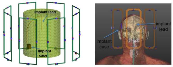
8 Channel Loop transmit array and a generic implant model in a uniform cylindrical phantom (left) and a head model (right) are shown.
Human model simulations were performed with the Finite Difference Time Domain (FDTD) SEMCAD EM Solver (SPEAG-SWITZERLAND) using the virtual family model “DUKE”. The model was cropped slightly above the chest but included the neck and the shoulders. The DBS was positioned in the head model similar to a previous work (24). The metallic implant case was located above the right ear. The implant lead extended subcutaneously and penetrated the skull at the vertex. To model the SAR around the implant, first, the incident field in the implant-free model was calculated. At this stage of the simulation, the DBS was not included in the numerical domain since it would require using a very high resolution for the FDTD calculations and is known to be very sensitive to the precise configuration of the electrodes. The obtained EM solution was interpolated to a uniform isotropic voxel size with a resolution of 2.2 mm. Then this incident field was used to solve for the EM field around the DBS using the Huygens simulation approach (24). As in the phantom, the DBS was modeled as an insulated copper wire (relative permittivity εr=3) and electrically connected to a copper implant case. The wire diameter and the insulation thickness were 1000μm and 250μm respectively, with insulation removed at the tip. Isotropic resolution of 100um was used to solve for the EM field around the implant.
Using the individual field solutions obtained from the EM simulations, we generated the electric fields Em and B1m+ from implant-friendly modes as shown below;
| [1] |
where Ei and B1i+ are the electric fields and B1+ fields generated by unit voltage excitation of each loop elements. αmi are the voltages that should be applied on the ith array element to generate the implant-friendly mode with index m. The specific phase and amplitude relations for αmi are shown in equation 2.
| [2] |
Here i is the channel index , N is the number of channels, φ0 is the steering angle for the field pattern, θ is an additional phase factor introduced to control B1+ perturbation around the tip, m is the mode index and j is √(−1). For a uniform phantom, note that m=1 and θ=0° would produce a current distribution similar to a linearly driven birdcage coil as discussed in a previous work (19). This excitation would produce a reduced electric field region at φ=φ0. The location of this region can be steered in any angular direction by simply changing φ0 On the other hand linear polarization may not always be sufficient to reduce the implant tip heating. For this purpose an additional phase factor θ was introduced.
Replacing the discrete angular locations of each transmit element with φ in the angular direction, equation 2 can be reduced to
| [3] |
which can also be written as
| [4] |
Equation 4 suggests that there are null or reduced electric field regions in the cylindrical phantom. Note that similar pattern can also be observed in the head model for different modes as approximately predicted by equation 3.
In the case of multi-channel excitation m is not limited to 1 as it would be in a linear excitation with a dual-drive birdcage coil. By using different m values one can generate different modes of a coil array and take advantage of additional degrees of freedom of multi-channel excitation.
In order to minimize the local SAR at the DBS lead tip, B1+ perturbation near the tip should be minimized. For that purpose, the maximum value of B1+ near the lead tip is calculated as a function of φ0, as the EM field inside the human head model is steered in an angular direction. In order to accurately calculate the peak B1+ field generated solely due to induced current on the implant lead, the background B1+ due to incident RF field was subtracted. The mean value of the background B1+ is calculated in a square ROI (2cm × 2 cm) 5 cm below the lead tip where the incident B1+ is similar to that which is experienced by the lead. The resulting variation of B1+ is fitted to a simple model as discussed previously (9).
In order to form the implant-friendly modes, the optimum φ0 and θ resulting in minimum lead tip B1+ perturbation were calculated. Then the implant friendly modes are constructed by inserting the optimal parameters for φ0 and θ and different values of m in equation 1. The maximum value for m is limited by the number of channels, N. Integer m values where N> m > (N/2) simply produce the same current distribution on the array elements compared to integer m values where N/2> m > 0. Therefore only integer m values N/2> m > 0 were used.
The implant-friendly modes were used in a spokes pulse design algorithm in order to maximize the flip angle excitation fidelity with hard constraints for global and local SAR (16). A different number of spokes may as well be used for the pulse design. We aimed for a flip angle homogeneity with NRMSE<5%. To guarantee such a uniform flip angle distribution we used 3 spokes.
We used 10 g SAR and global SAR limits of 10 W/kg and 3.2 W/kg in all pulse calculations. In this optimization, 10 g SAR matrices for each mode were compressed to a smaller set of VOP (Virtual Observation Points) (25) in the implant-free model. For this purpose, we calculated the Q matrices. The Q matrices were then used in the pulse design optimization. While all the components of a 10g SAR map were present, we did not actually form a 10 g SAR map until after the pulse was optimized. After the pulse is designed, we then recalculated the 10g map for visualization purposes. Note that this SAR model did not incorporate the DBS lead and was used solely to control local SAR and global SAR in other regions of the head.
The mode weights, Am , were optimized in the pulse design to generate a uniform flip angle distribution within an axial slice. Each spoke pulse had the same sinc profile (3 lobes, 0.8 ms second duration, a duty cycle of 10%). Pulses were designed to achieve a uniform target flip angle profile of 60 degrees. We aimed for a fairly large flip angle to demonstrate a case where implant heating is a significant problem. Pulse design could also be made for very small flip angles; however in that case the tip SAR would not be a constraining safety factor. However we didn’t use higher flip angle values because the pulse design algorithm operated better in small flip angle regime. We chose 60 degrees as an intermediate point to demonstrate the SAR reduction concept.
The locations of the spoke pulses in k space were chosen as explained in a previous work (26). The first spoke was placed at the origin of the k space. The other two spokes were placed on a circular contour of diameter 1/D (1/m) at various angular locations differing by 45 degrees. Here D is the diameter of the phantom or the average dimension of the cross section of the head. The solution that produced maximum flatness were selected.
After pulse optimization using the implant-friendly modes in the implant-free head, the 10 g SAR was recorded by averaging SAR in the neighborhood of voxels that approximated 10g tissue. The SAR around the implant tip was recorded in 1 g volume using the pulse design solution and the Huygens generated fields around the high-resolution implant model.
Results
Figure 2 shows the SAR distribution in the phantom and the head model around the lead in the axial and sagittal plane for the first mode of the transmit array. Each panel shows a different φ0 angle. φ0 was changed over the interval [0°, 75°] with a step size of Δφ0 15°. Also in both phantom and head model, the maximum SAR was observed around the tip of the lead for the lower values of φ0 but was reduced to below other hotspots by steering φ0 for the single mode of the transmit array. In both cases excitation with the lowest SAR could be taken as the implant-friendly mode if full confidence could be placed in the electromagnetic model.
Figure 2.
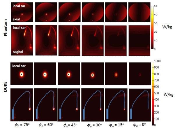
SAR distribution around the lead in the phantom and in the DUKE model is shown in axial and sagittal planes. SAR around the implant can be reduced by steering a single mode of the transmit array (mode 1 shown as an example) by changing φ0 between 0° and 75°
In real life applications, it may not always be possible to model the exact implant lead geometry. In that case, we propose tuning the implant-friendly modes by experimentally minimizing the B1+ perturbation around the lead tip using a conservative power level. Figure 3 shows the variation of B1+ perturbation around the lead tip in the DUKE head model with respect to φ0 (changed between 0° and 180° with an interval of 1° to obtain the B1+ plot). By finding the best solution that fits the B1+ variation around the lead, we were able to calculate the optimal parameters for φ0 and θ that reduces B1+ perturbation and local SAR near the lead tip. As seen in Figure 3, mode 1 steered with an angle of −87° and a phase of 309° significantly reduces the B1+ variation around the lead in comparison to the birdcage mode of the array. A similar evaluation was made for all the modes except for mode 4. The optimal φ0 and θ parameters were calculated as [−87°,309°], [−4.5°,11°] and [−26°, 202°] for mode 1,2 and 3 respectively. Evaluation for mode 4 was not performed since the B1+ contribution due to that mode was significantly smaller than the others. Thus φ0 = 0°, θ=0° was used for mode 4.
Figure 3.
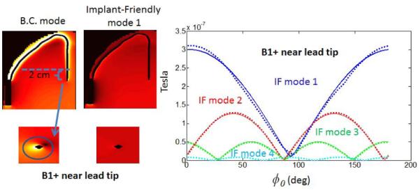
B1+ perturbation varies with respect to steering angle φ0. φ0= − 87° and θ =309° values are used to cancel the B1+ around the lead tip with mode 1. Comparison with BC mode is shown on the left.
Figure 4 shows the local SAR variation around the lead tip in the DUKE head model with respect to φ0 (changed between 0° and 180° with an interval of 1° to obtain the 1 g average SAR plot). Note that the minimum SAR locations (φ) perfectly coincide with the minimum B1+ locations in the plots in Figure 3. Figure 4 shows that mode 1 steered with an angle of −87° and a phase of 309° causes 0.0045 W/kg 1 g average SAR near the lead tip. On the other hand the birdcage mode of the array generates 0.2 W/kg of SAR near the tip.
Figure 4.
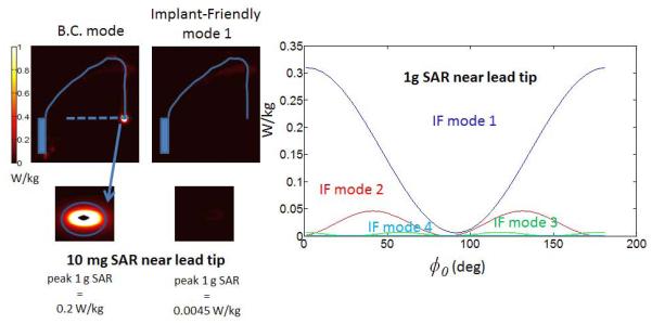
SAR around the lead varies with respect to steering angle φ0. φ0=−87° and θ =309° values are used to cancel the B1+ around the lead tip with mode 1. Comparison with BC mode is shown on the left.
Figure 5 shows the local SAR variations due to individual modes with their optimal φ0, and θ parameters. Note that for the uniform phantom, each mode has a unique SAR pattern determined by the mode index m. For example, mode 1 has a reduced SAR region at φ=0 and φ=180° whereas mode 2 has reduced SAR regions at φ=0 and φ=90° φ= 180° and φ=270°. This pattern can easily be predicted by looking at the sinusoidal expression for current pattern shown in equation 4.
Figure 5.
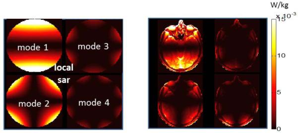
SAR pattern due to implant-friendly modes of the transmit array are shown in a phantom (left) and the head model (right). Modes have “reduced SAR” regions around the implant. The reduced SAR region can be steered in to any angular direction by changing φ.
Figure 6 shows the B1+ patterns obtained by individual modes in the phantom and human head models. Note that the mode with the best B1+ uniformity in the axial plane is mode 1. On the other hand the flip angle excitation is not uniform for any of the individual modes.
Figure 6.
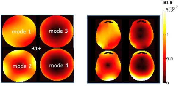
B1+ pattern due to implant-friendly modes of the transmit array are shown in a phantom (left) and the head model (right). Each single mode has a non-uniform B1+ pattern. An appropriate pulse must be designed to obtain a uniform flip angle pattern (see Figure 7).
In order to optimize excitation fidelity, one needs to use all of the implant-friendly modes as part of the SAR-optimized pulse design. Figure 7 shows the flip angle and the SAR distribution in the uniform phantom and the head model obtained by the 3-spokes pulse design. In both cases the algorithm obtained a uniform flip angle profile in the chosen axial plane. The percent RMSE error obtained in the phantom and the head model was 3.1% and 2.6% respectively. The axial plane containing the maximum local 10 g SAR is also shown. The pulse design reduced the SAR at the implant tip to a degree such that the maximum local SAR hotspot occurs elsewhere. The global and peak-local SAR values obtained as a result of pulse design were 1.31 W/kg and 5.51 W/kg for the phantom and 0.48 W/kg and 4.52 W/kg for the head model. In both cases the algorithm guaranteed that safety limits are not exceeded. Finally 1g average SAR is calculated near the implant tip as 0.1 W/kg using the Huygens generated fields around the high-resolution implant model. As a comparison, 1 g average SAR is calculated as 31.2 W/kg for a simple quadrature birdcage excitation performed at the same RF duty-cycle and flip angle without any sort of SAR mitigation.
Figure 7.
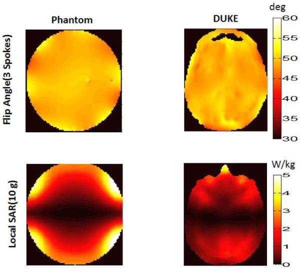
A uniform flip angle profile is obtained in phantom(upper row, left) and the head model(upper row, right) as a result of 3 spokes pulse design that utilizes the implant-friendly modes of the transmit array. NRMSE values obtained for the phantom and the head model were 3.1% and 2.6% respectively. An implant-friendly SAR pattern is obtained in the phantom (bottom row, left) and in the head model (bottom row, right) as a result of 3 spokes pulse design which utilized the if modes of the array. Peak 10 g average SAR and global SAR due to pulse design is calculated as 5.51 W/kg, 1.31 W/kg for the phantom and 4.52 W/kg, 0.48 W/kg respectively for the head/shoulder model.
Discussion and Conclusions
We present a pulse design strategy based on using implant-friendly modes. In this procedure, the experimental study of a patient with a DBS implant would proceed in the following four steps. First, an EM model is chosen that best matches the patient (without the implant present) and is used to calculate the E and B fields in the head-only model. Second, we experimentally determine the implant-friendly modes by measuring the B1+ perturbation around the lead as the two parameters in the mode are adjusted. Since we seek the null in B1+ due to induced current around the tip, and this will be difficult to determine in low SAR scans, we fit a model of the data in the vicinity of the null to estimate the optimal parameters, φ0 and θ. Third, we form the 4 implant-friendly modes and generate the VOP Q matrices for these modes in the head-only model (no implant). A model of the implant is not needed at the time of the B1+ perturbation measurement since the local SAR generated by the current on the leads is low and the SAR hotspot is away from the leads. Finally, we use these VOP matrices to optimize the pTx pulse for excitation fidelity with constrained global and local SAR in order to control SAR in regions outside of the DBS device. Note that the pulse design does not directly require detailed knowledge of the implant. By limiting the use of detailed implant models in the procedure and relying instead on empirically determined factors, we hope to make the procedure less reliant on an accurate model of the implant. In fact, a comparison beween the SAR results of the phantom and the head model in Figure 2 reflects the effects of modeling the EM problem at low resolution. For the phantom, SAR was calculated at 3mm resolution. For the SEMCAD Duke model SAR maps are calculated with a very fine resolution (100um) using a special tool from the commercial software “Huygens Source” and then averaged over 10mg. This produces a more meaningful estimate of the high SAR near the small tip.
The pulse design strategy described in this work utilizes modes of an array that can individually reduce the SAR around the implant lead. An important consideration is that the implant-friendly modes were determined empirically from the B1+ perturbation visible in lowSAR scanning, thus they can have model-based and experimental validation. B1+ can be canceled completely by steering the field pattern of each mode in an appropriate location and choosing the optimal phase θ.
In practice a low-SAR pre-scan may be performed with a small flip angle excitation. Small flip angle ensures the detection of the signal solely due to induced currents on the lead and not due to excitation of spins with the RF coil. In addition it guarantees patient RF safety. In a previous work, 1 deg flip angle excitation was used with a dual-drive excitation (9) as a pre-scan to experimentally determine the safe excitation mode that reduces lead tip temperature. In a more recent work a concept based on s parameter measurements was used to calculate the pTx null mode of a birdcage coil to reduce the interaction between two ports of the coil and metallic leads in phantoms (27). Similar pre-scan techniques can be used to experimentally determine the implant friendly modes of a multi-channel pTx array.
The relation between electric fields-SAR and B1+ was investigated previously (28) in complex body models without the presence of an implant. In this work we did not attempt to create maps of the E field of the modes via B1+ maps. Our main goal was to minimize the current on the lead. Flip-angle deviation a few mm away from the wire can easily be converted to a B1+ field (on one side of the wire this extra B1+ adds to the coil’s B1+, creating a higher flip angle, while on the opposite side of the wire it subtracts, creating a lowered flip-angle). Thus the local extrema in the flip angle map occured from the B1+ created by the current along the wire adding or subtracting from the coil’s B1+. Since we were only minimizing this quantity, we did not actually perform the calculation of the current on the wire, but it would be straightforward in principle(5). Our assumption was that by minimizing the RF current on the wire in the formation of the modes, we will be minimizing the current density in the tissue in the immediate vicinity of the tip (based on the assumption that all current must exit the tip, at which point it diverges into the tissue.) We confirmed this assumption with our numerical simulations.
Modes were used instead of the individual coil fields for the pulse design. For this purpose, the contribution of each mode to B1+ needs to be measured. We believe that this should be easier than attempting to optimize all channel currents simultaneously in order to cancel B1+. Instead one can choose optimal φ0 and θ for each mode and generate implant-friendly modes. As shown in a previous work (9), there is always some priori information on what the optimal φ0 should be. If the location of the DBS is known, then the φ0 angle that approximates the location of the implant is a good starting point for B1+ perturbation minimization. Therefore one could easily limit the search for an optimal φ0 in a small interval around the position of the lead rather than searching in the [0°, 180°] interval as discussed in the methods section. For cases where the location of the lead is not known a low flip angle image can be quickly acquired to locate the implant in the head.
We used the four implant friendly modes of an eight channel array to reduce the SAR at the tip of a DBS, and obtain a uniform flip angle distribution with SAR constraints. The minimum number of modes and channels required to achieve these tasks is an important issue that needs to be investigated. For cylindrically arranged arrays (N elements), like the ones discussed, it will always be natural to form N/2 implant-friendly modes. If adding extra array elements (M layers) along the z direction is an option;rings of coils can be placed around the head to contribute N/2 usable modes (per row) giving a total of N*M/2. Note that this configuration will have extra parameters to tune (the relative phase and amplitude between the rows of coils) since it has an extra dimension compared to our example.On the other handincreasing the number of channels that is generally used for ptx isalso an important hardware constraint and has many possible benefits as shown in the previous works discussing the ultimate SAR and effect of adding an extra coil dimension for pTx (29-31). However in this work, we did not model enough coil varieties to answer the question of how the performance of the implant-friendly mode approach varies with number of coils.
The pulse design algorithm discussed in this work enabled us to constrain peak local SAR and global SAR. For that purpose one would need to calculate the local and global SAR matrices in an implant free head model which requires a detailed EM model of the patient. Patient models can be obtained from the segmentation of previous MRI scans performed before implantation or by using the closest possible model from a set of models presented in a previous work (32)
The implant-friendly modes were generated by finding optimal parameters that minimized the B1+ perturbation around the lead tip. As it was demonstrated with EM simulations, this approach also reduced the tip SAR significantly. In our approach we assumed that the tip of the lead is the most critical point where the SAR should be minimized. Although there could be examples where multiple hot spots may be observed along certain metallic devices (33), multiple hot spots are not expected for the DBS leads that are short compared to wavelength.
10 g averaging was used to calculate local SAR in the implant free model. For each voxel in the body/phantom a neighborhood of voxels that approximates 10g tissue is chosen. Corresponding volume was used to calculate 10g SAR. The use of 10 g averaging is standard for applications that do not include metallic implants. However, for very small conductors such as implant leads and electrodes, 10g averaging may not be appropriate. The heating around the tip of an implant occurs in a very small volume. Therefore we calculated 1g average SAR at the implant tip.
Coupling between the individual coils was not modeled in our EM simulations. Although typically certain amount of inductive coupling exists between the elements of a loop array, these effects can be minimized by using standard decoupling methods. In a real life experiment, the B1+ maps of the modes would be acquired in the presence of any coupling that the coils may have. In that case, the pulse design algorithm would include the effect of coil coupling while maximizing the flip angle homogeneity. Coupling between the elements may also affect the global and local SAR as well. However this problem can also be overcome by calculating the electric fields and the 10 g SAR matrices in the presence of EM coupling as discussed in a previous work (18).
The proposed method utilized the degrees of freedom of an 8 channel array to enable safer imaging of patients with DBS implants. The increased number of channels in the pTx system enabled control of various safety parameters including global SAR, peak local SAR around the lead and elsewhere. Although clinical pTx systems with more than two channels are currently not available, the potential to safely image patient groups not previously accessible may help justify the cost of more highly parallel pTx hardware.
In this work, we demonstrated a workflow that allows pTx arrays to be used with pulse design optimization to improve RF safety for patients with DBS implants. We validated the performance of the method using electromagnetic modeling of a head + DBS lead + coil geometry. Implant-friendly modes of an 8 channel loop array were used to reduce SAR around a generic DBS implant. The method allowed us to optimize the RF pulses for SAR without having a detailed model of the individual patent’s implant geometry.
Acknowledgements
The authors acknowledge support from the National Institutes of Health NIBIB grants R01EB006847 and R01EB007942. This project has been financially supported by the Comunidad de Madrid, Madrid-MIT M+Vision Consortium.
Grant Support: R01EB006847, P41EB015896, Siemens-MIT CKI Alliance. This project is also supported by the Comunidad de Madrid and the Madrid MIT M+Vision Consortium
References
- 1).Nitz WR, Oppelt A, Renz W, Manke C, Lenhart M, Link J. On the heating of linear conductive structures as guide wires and catheters in interventional MRI. Journal of Magnetic Resonance Imaging. 2001;13:105–114. doi: 10.1002/1522-2586(200101)13:1<105::aid-jmri1016>3.0.co;2-0. [DOI] [PubMed] [Google Scholar]
- 2).Yeung CJ, Susil RC, Atalar E. RF safety of wires in interventional MRI: Using a safety index. Magn Reson Med. 2002;47:187–193. doi: 10.1002/mrm.10037. [DOI] [PubMed] [Google Scholar]
- 3).Henderson JM, Tkach J, Phillips M, Baker K, Shellock FG, Rezai AR. Permanent neurological deficit related to magnetic resonance imaging in a patient with implanted deep brain stimulation electrodes for Parkinson's disease: case report. Neurosurgery. 2005>;57(5) doi: 10.1227/01.neu.0000180810.16964.3e. [DOI] [PubMed] [Google Scholar]
- 4).Yeung CJ, Atalar E. A Green’s function approach to local rf heating in interventional MRI. Med Phys. 2001;28:826–832. doi: 10.1118/1.1367860. [DOI] [PubMed] [Google Scholar]
- 5).van den Bosch MR, Moerland MA, Lagendijk JJW, Bartels LW, van den Berg CAT. New method to monitor RF safety in MRI-guided interventions based on RF induced image artefacts. Med Phys. 2010;37:814–821. doi: 10.1118/1.3298006. [DOI] [PubMed] [Google Scholar]
- 6).Gray RW, Bibens WT, Shellock FG. Simple design changes to wires to substantially reduce MRI-induced heating at 1.5 T: implications for implanted leads. Magnetic Resonance Imaging. 2005;23:887–891. doi: 10.1016/j.mri.2005.07.005. [DOI] [PubMed] [Google Scholar]
- 7).Bottomley PA, Kumar A, Edelstein WA, Allen JM, Karmarkar PV. Designing passive MRI-safe implantable conducting leads with electrodes. Med Phys. 2010;37(7):3828–3843. doi: 10.1118/1.3439590. [DOI] [PubMed] [Google Scholar]
- 8).Eryaman Y, Akin B, Atalar E. Reduction of implant RF heating through modification of electric field. Magn Reson Med. 2011;65:1305–1313. doi: 10.1002/mrm.22724. [DOI] [PubMed] [Google Scholar]
- 9).Eryaman Y, Turk E. A, Oto C, Algin O, Atalar E Reduction of the radiofrequency heating of metallic devices using a dual-drive birdcage coil. Magn Reson Med. 2012 doi: 10.1002/mrm.24316. doi: 10.1002/mrm.24316. [DOI] [PubMed] [Google Scholar]
- 10).Metzger GJ, Snyder C, Akgun C, Vaughan T, Ugurbil K, de Moortele V. Local B1+ shimming for prostate imaging with transceiver arrays at 7T based on subject-dependent transmit phase measurements. Magn Reson Med. 2008;59(2):396–409. doi: 10.1002/mrm.21476. [DOI] [PMC free article] [PubMed] [Google Scholar]
- 11).Setsompop K, Alagappan V, Gagoski B, et al. Slice-Selective RF Pulses for In Vivo B1 Inhomogeneity Mitigation at 7 Tesla Using Parallel RF Excitation With a 16-Element Coil. Magn Reson Med. 2008;60:1422–1432. doi: 10.1002/mrm.21739. [DOI] [PMC free article] [PubMed] [Google Scholar]
- 12).Thalhammer C, Renz W, Winter L, et al. Two-Dimensional sixteen channel transmit/receive coil array for cardiac MRI at 7.0 T: Design, evaluation, and application. J Magn Reson Imaging. 2012;36:847–857. doi: 10.1002/jmri.23724. [DOI] [PMC free article] [PubMed] [Google Scholar]
- 13).Gräßl A, Winter L, Thalhammer C, et al. Design, evaluation and application of an eight channel transmit/receive coil array for cardiac MRI at 7.0 T. Eur J Radiol. 2011;82(5):752–759. doi: 10.1016/j.ejrad.2011.08.002. [DOI] [PubMed] [Google Scholar]
- 14).Adriany G, Auerbach EJ, Snyder CJ, Gözübüyük A, Moeller S, Ritter J, Van de Moortele PF, Vaughan T, Uğurbil K. A 32-channel lattice transmission line array for parallel transmit and receive MRI at 7 tesla. Magn Reson Med. 2010;63(6):1478–1485. doi: 10.1002/mrm.22413. [DOI] [PMC free article] [PubMed] [Google Scholar]
- 15).Zhu Y. Parallel Excitation With an Array of Transmit Coils. Magn Reson Med. 2004;51:775–784. doi: 10.1002/mrm.20011. [DOI] [PubMed] [Google Scholar]
- 16).Katscher U, Börnert P, van den Brink JS. Transmit SENSE. Magn Reson Med. 2003;49:14. doi: 10.1002/mrm.10353. [DOI] [PubMed] [Google Scholar]
- 17).Grissom W, Yip CY, Zhang Z, Stenger VA, Fessler JA, Noll DC. Spatial domain method for the design of RF pulses in multicoil parallel excitation. Magn Resona Med. 2006;56:620–629. doi: 10.1002/mrm.20978. [DOI] [PubMed] [Google Scholar]
- 18).Guérin B, Gebhardt M, Cauley S, Adalsteinsson E, Wald LL. Local specific absorption rate (SAR), global SAR, transmitter power, and excitation accuracy trade-offs in low flip-angle parallel transmit pulse design. Magn Reson Med. 2013 doi: 10.1002/mrm.24800. doi:10.1002/mrm.24800. [DOI] [PMC free article] [PubMed] [Google Scholar]
- 19).Lee J, Gebhardt M, Wald LL, Adalsteinsson E. Local SAR in Parallel Transmission Pulse Design. Magn Reson Med. 2011;67:1566–1578. doi: 10.1002/mrm.23140. [DOI] [PMC free article] [PubMed] [Google Scholar]
- 20).van den Bergen B, van den Berg CAT, Klomp DW, Lagendijk JJ. SAR and power implications of different RF shimming strategies in the pelvis for 7T MRI. J Magn Reson Imaging. 2009;30(1):194–202. doi: 10.1002/jmri.21806. [DOI] [PubMed] [Google Scholar]
- 21).Hoyos-Idrobo A, Weiss P, Massire A, Amadon A, Boulant N. On Variant Strategies to Solve the Magnitude Least Squares Optimization Problem in Parallel Transmission Pulse Design and Under Strict SAR and Power Constraints. IEEE Trans Med Imag. 2014;33(3):739–748. doi: 10.1109/TMI.2013.2295465. [DOI] [PubMed] [Google Scholar]
- 22).Eryaman Y, Guerin B, Adalsteinsson E, Wald LL. Parallel Transmit Pulse Design with Implant-Friendly Modes. Proceedings of the 21th Annual Meeting of ISMRM; Salt Lake City. 2013. p. 2215. [Google Scholar]
- 23).Etezadi-Amoli M, Stang P, Zanchi MG, Pauly JM, Scott GC, Kerr AB. Controlling Induced Currents in Guidewires Using Parallel Transmit. Proceedings of the 18th Annual Meeting of ISMRM; Stockholm, Sweden. 2010. p. 777. [Google Scholar]
- 24).Cabot E, Lloyd T, Christ A, Kainz W, Douglas M, Stenzel G, Wedan S, Kuster N. Evaluation of the RF Heating of a Generic Deep Brain Stimulator Exposed in 1.5 T Magnetic Resonance Scanners. Bioelectromagnetics. 2013;34:104–113. doi: 10.1002/bem.21745. [DOI] [PubMed] [Google Scholar]
- 25).Eichfelder G, Gebhardt M. Local specific absorption rate control for parallel transmission by virtual observation points. Magn Reson Med. 2011;66(5):1468–1476. doi: 10.1002/mrm.22927. [DOI] [PubMed] [Google Scholar]
- 26).Setsompop K. Massachusetts Institute of Technology; Cambridge: 2008. Design Algorithms for Parallel Transmission in Magnetic Resonance Imaging; p. 104. [Google Scholar]
- 27).Ellenor CW, Stang PP, Etezadi-Amoli M, Pauly JM, Scott GC. Offline impedance measurements for detection and mitigation of dangerous implant interactions: An RF safety prescreen. Magn Reson Med. 2014 doi: 10.1002/mrm.25202. DOI:10.1002/mrm.25202. [DOI] [PMC free article] [PubMed] [Google Scholar]
- 28).Katscher U, Voigt T, Findeklee C, Vernickel P, Nehrke K, Dossel O. Determination of Electric Conductivity and Local SAR Via B1 Mapping. IEEE Trans Med Imag. 2009;28(9):1365–74. doi: 10.1109/TMI.2009.2015757. [DOI] [PubMed] [Google Scholar]
- 29).Guerin B, Villena JF, Polimeridis AG, Adalsteinsson E, Daniel L, White J. Wald LL The ultimate SNR and SAR in realistic body models. Proceedings of the Joint Annual Meeting of ISMRM; Milan, Italy. 2014. p. 617. [Google Scholar]
- 30).Lattanzi R, Sodickson DK, Grant AK, Zhu Y. Electrodynamic constraints on homogeneity and radiofrequency power deposition in multiple coil excitations. Magn Reson Med. 2009;61(2):315–334. doi: 10.1002/mrm.21782. [DOI] [PMC free article] [PubMed] [Google Scholar]
- 31).Guerin B, Gebhardt M, Serano P, Adalsteinsson E, Hamm M, Pfeuffer J, Nistler J, Wald LL. Comparison of simulated parallel transmit body arrays at 3 T using excitation uniformity, global SAR, local SAR, and power efficiency metrics. Magn Reson Med. 2014 doi: 10.1002/mrm.25243. DOI:10.1002/mrm.25243. [DOI] [PMC free article] [PubMed] [Google Scholar]
- 32).Christ A, Kainz W, Hahn EG, et al. The Virtual Family—development of surface-based anatomical models of two adults and two children for dosimetric simulations. Phys Med Biol. 2010;55(2):N23. doi: 10.1088/0031-9155/55/2/N01. [DOI] [PubMed] [Google Scholar]
- 33).Ladd ME, Quick HH. Reduction of resonant RF heating in intravascular catheters using coaxial chokes. Magn Reson Med. 2000;43:615–619. doi: 10.1002/(sici)1522-2594(200004)43:4<615::aid-mrm19>3.0.co;2-b. [DOI] [PubMed] [Google Scholar]


