Abstract
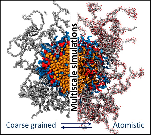
Delivery of poorly soluble anticancer drugs can be achieved by employing polymeric drug delivery systems, capable of forming stable self-assembled nanocarriers with drug encapsulated within their hydrophobic cores. Computational investigations can aid the design of efficient drug-delivery platforms; however, simulations of nanocarrier self-assembly process are challenging due to high computational cost associated with the large system sizes (millions of atoms) and long time scales required for equilibration. In this work, we overcome this challenge by employing a multiscale computational approach in conjunction with experiments to analyze the role of the individual building blocks in the self-assembly of a highly tunable linear poly(ethylene glycol)-b-dendritic oligo(cholic acid) block copolymer called telodendrimer. The multiscale approach involved developing a coarse grained description of the telodendrimer, performing simulations over several microseconds to capture the self-assembly process, followed by reverse mapping of the coarse grained system to atomistic representation for structural analysis. Overcoming the computational bottleneck allowed us to run multiple self-assembly simulations and determine average size, drug-telodendrimer micellar stoichiometry, optimal drug loading capacity, and atomistic details such hydrogen-bonding and solvent accessible area of the nanocarrier. Computed results are in agreement with the experimental data, highlighting the success of the multiscale approach applied here.
I. Introduction
Polymeric micelles are a promising class of drug delivery carriers in the field of nanomedicine due to their tunable physiochemical properties. Typically, micelle based drug delivery carriers are prepared from amphiphilic block copolymers that self-assemble into nanoarchitectures with a hydrophobic core capable of encapsulating drug molecules and a biocompatible hydrophilic shell.1,2 Within their hydrophobic core, the micelles can encapsulate cancer drugs such as paclitaxel (PTX), which is otherwise difficult to administer due to its limited solubility in water.3−6 Meanwhile, the hydrophilic shell of the micelle protects the drug from degradation and passively transports it to the tumor sites without undesirable side effects to the healthy cells. The efficacy of anticancer nanocarriers lies in how readily they can extravasate through the leaky tumor vasculature and get retained in the interstitial spaces of tumor for sustained drug release.7,8
Designing optimal nanocarriers, however, is challenging due to factors such as poor drug loading capacity, ineffective shielding of the drug in the core, size distribution, poor reproducibility, and lack of desired physicochemical properties.9,10 These chemical instabilities can lead to the disassembly of the micellar structure resulting in precipitation and subsequent elimination from the body through the reticulo-endothelial system (RES).11−13 Most often development of the optimal polymeric nanocarrier is a trial-and-error process because the best polymeric system is not always obvious.1,14 This approach is frequently associated with high cost of production, relatively low drug loading efficiency, and limited capability for further optimization.
Numerous amphiphilic copolymers have been studied for anticancer drug delivery but with limited success in majority of the cases.1,15,16 Commonly used core-forming building blocks for cancer drug delivery include poly(esters) such as poly(lactic acid),17 poly(lactic-co-glycolic acid),18 poly(propylene oxide),19 and poly(l-lysine).20 In addition, several other hydrophilic shell-forming copolymers include poly(N-vinyl-2-pyrrolidone),21 poly[N-(2-hydroxypropyl) methacrylamide],22 and poly(N-isopropylacrylamide).23 Despite the plethora of copolymers, poly(ethylene glycol) (PEG) is the most widely utilized shell forming polymer and is one of the polymers approved for use by the Food and Drug Administration.24−26 In micelles, PEG forms a dense, brushlike, nonionic shell surrounding the core that prevents precipitation, aggregation, and elimination of the drug from the body. Studies have shown that PEGylated surfaces have longer blood circulation times and undergo slower uptake by the RES in the body.24−27
In recent years, a versatile linear polyethylene glycol-b-dendritic oligo(cholic acid) copolymer (Figure 1), called telodendrimer has been developed that is capable of forming nanocarriers with highly tunable sizes between 15–160 nm and drug loading of up to 36% (w/w PTX/telodendrimer).28−31 The telodendrimer molecule consists of hydrophilic polyethylene glycol (PEG) chain attached to the core forming cholic acid (CA) groups through dendritic polylysine (LYS) groups.28 Cholic acid is a natural surfactant with facial amphiphilicity (polar and nonpolar faces) that makes it a desirable building block for telodendrimers. Throughout the text, telodendrimeric structures are represented in PEGxCAy notation, where the variable x represents the molecular weight of PEG chains in kilodaltons (2K, 3K, or 5K) and y represents the number of cholic acid groups (4, 6, or 8).27,28 The modular structure of the telodendrimer allows for easy manipulations of the building blocks for obtaining the desired properties.32−35 There is experimental evidence that the drug loading capacity of the telodendrimer micelle can be optimized by changing the CA groups attached to the dendritic domain in the telodendrimer.27,28 Further improvements of the telodendrimer micelles will require a systematic evaluation of the building blocks.
Figure 1.
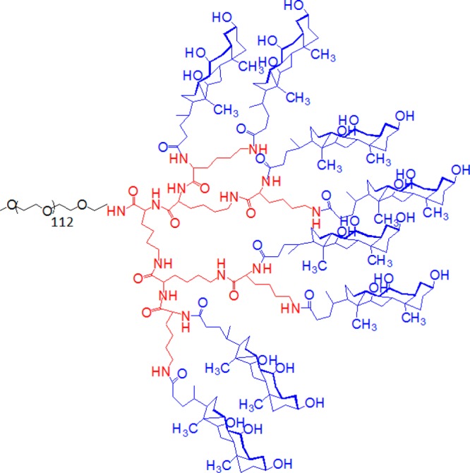
Atomistic structure of PEG5KCA8 telodendrimer composed three building blocks: PEG (gray), CA (blue), and dendritic LYS (red) groups.
To design the optimal delivery system for hydrophobic drug PTX, we employ synergistic computational and experimental approaches to investigate individual building blocks of the telodendrimer and their overall drug loading capacities as self-assembled micelles. The use of computational approach for analyzing telodendrimer building blocks provides essential molecular level feedback to the experiments for systemically optimizing the nanocarrier.36,37 Additionally, simulations provide the molecular description of the self-assembly process, the composition of the micelles formed, size distribution, shape, and polydispersity of the equilibrated system. In the present work, a series of telodendrimers with varying PEG chain length, facial amphiphilicity of CA groups, and number of CA groups have been developed to investigate the effects of individual components on micelle stability. The structure of micelle and drug loading properties of the telodendrimers are also characterized both experimentally and computationally.
It would be prohibitively expensive to simulate the dynamics of micelle formation in an all-atom representation over the relevant time and length scales required for equilibration. In order to overcome such limitations, we applied a multiscale approach of first mapping the atomistic telodendrimeric structure to a coarse-grained (CG) representation that preserves the chemical properties while reducing the number of particles in the system that need to be simulated.38−40 Specifically, we utilized the MARTINI framework that offers self-consistent CG descriptions of polymers, surfactants, peptides and proteins, lipids, and solvents.38,39,41−44 The MARTINI approach maps three to four heavy atoms into one CG bead. These beads interact through a set of short-ranged Lennard–Jones potentials with appropriate charge and polarity.40,45,46 Besides the reduction in the number of particles in a simulation, the CG representation eliminates the need to use small integration time-steps, and enhances the computational productivity by requiring only a fraction of the computational resources.47−50 For the purpose of analysis, however, we developed a reverse mapping algorithm to obtain the atomistic level detail once the telodendrimers aggregate into micelles. Reverse mapping of coarse grained structures to atomistic resolution have recently been reported for a variety of structurally diverse chemicals.51−53 The enormity of micelle sizes (∼250 000 CG beads) and the need for atomistic detail (1.1 million atoms) necessitated the use of the multiscale approach to consolidate the strengths of the both the coarse grained and all-atom resolutions.
II. Computational Approach
II.A. Development of Coarse Grained Description of Telodendrimers
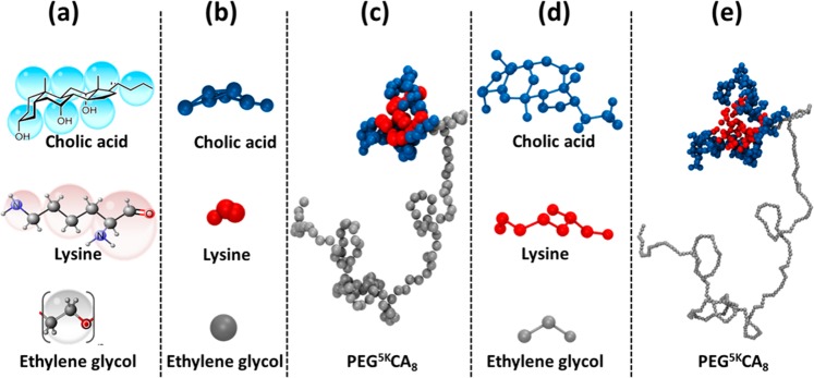
The telodendrimer building blocks (cholic acid, lysine, and poly(ethylene glycol)) were individually coarse-grained using the MARTINI approach.38,45,46 The mapping scheme for each block is shown in Figure 2. The amphiphilic nature of the cholic acid molecule was preserved in the CG representation by assigning polar (SP5) and nonpolar (SC1) type to the beads forming the hydrophilic and hydrophobic faces, respectively. It is expected that facial amphiphilicity of CA will provide hydrophilic and hydrophobic balance between the core-shell motif of the micelle, essential for drug loading and the stability of micelles. The bead assignment for PEG and LYS was adopted from the MARTINI parameter set available in the literature.27−29 The telodendrimers were then constructed by combining the CG building blocks, for example, PEG5KCA8 telodendrimer was made by combining 112 PEG beads, 7 LYS units, and 8 CAs. Coarse grained topology of PEG5KCA8 telodendrimer (including the CG bead types, bonded and nonbonded parameters) is provided in the Supporting Information.
Figure 2.
Multiscale representation of a telodendrimer molecule. (a) Atomistic to coarse grain mapping scheme, (b) CG building blocks, (c) CG PEG5KCA8 telodendrimer, (d) reverse mapped atomistic positions (before energy minimization) of each the three building blocks, and (e) atomistic, reversed map PEG5KCA8 telodendrimer. Color scheme of the building blocks: PEG (gray), LYS (red), and CA (blue).
II.B. Simulation Details
The molecular dynamics simulations were performed for 12 telodendrimeric systems in the coarse grained (CG) representation. The PTX coarse grained mapping scheme was adopted from previously published literature.42 The polarized water model was tested as a solvent but due to the nonionic nature of the system standard MARTINI water39 (with 10% antifreeze) was sufficient for all the simulations presented here. Twelve telodendrimers (labeled I-XII) with variable number of cholic acid groups and variable PEG chains, such as PEG5KCA8, PEG3KCA8, PEG2KCA8, PEG3KCA6, and PEG2KCA4, were simulated for a range of drug loading capacities including those without any drug molecules. The contents of the simulation box for each micelle system are provided in Table 1. The simulations were performed with the GROMACS 4.5.5 software package.38,45,46 Each system was energy minimized using the steepest decent algorithm with a 20 fs time step. The systems were then equilibrated for 10 ns in isothermal–isochoric NVT ensemble (fixed number of particles N, volume V, and temperature T) at T = 300 K followed by 10 ns in isothermal–isobaric NPT (fixed number of particles N, pressure P, and temperature T) ensemble at P = 1 atm and T = 300 K. The production runs were performed for 1.5 μs in the NPT ensemble using the Nosé–Hoover thermostat and the Parrinello–Rahman barostat at T = 300 K and P = 1 atm with 20–30 fs time steps.54−56 A plot of the total energy of the system shows that equilibration is achieved within 200–500 ns of the simulation (Supporting Information). Water and the telodendrimers were coupled to separate thermostats, and the entire system was coupled to the barostat isotropically. The nonbonded interactions terms were computed with the standard cutoff of 1.2 nm. Using the standard shift function, the LJ potential was shifted from r = 0.9 nm to the cutoff distance so that both the energy and force smoothly vanish at the cutoff value. A typical system contained a total of 100–300 telodendrimers, 0–400 drug molecules, and 200 000 CG water molecules, corresponding to a total number of approximately 250 000 CG sites. Simulations for each of the 12 systems were repeated 3 times with new initial configuration and a new initial random seed for velocity distribution.
Table 1. Simulation Parameters and Sizes of Self-Assembled Micelles.
| no.
of units in simulation box |
avg
micelle diameter (nm)a |
avg
number of units in micelle |
||||||||
|---|---|---|---|---|---|---|---|---|---|---|
| system | telodendrimer | PTX/telo (% w/w) | box size (nm) | water | PTX | telo | expt | simb | PTX | Telo |
| I | PEG2KCA4 | − | 25.0 | 117 423 | − | 200 | 10.0 ± 2.0 | 11.2 ± 3.1 | − | 17 |
| II | PEG2KCA8 | − | 25.0 | 117 161 | − | 200 | − | − | − | − |
| III | PEG3KCA6 | − | 25.0 | 116 572 | − | 200 | 13.0 ± 4.5 | 11.9 ± 5.5 | − | 19 |
| IV | PEG3KCA8 | − | 25.0 | 115 774 | − | 200 | 19.5 ± 4.5 | 17.5 ± 3.4 | − | 21 |
| V | PEG5KCA8 | − | 25.0 | 112 530 | − | 200 | 18.0 ± 4.0 | 18.7 ± 3.2 | − | 25 |
| VI | PEG5KCA8 | − | 30.0 | 195 130 | − | 300 | 18.0 ± 4.0 | 19.1 ± 4.1 | − | 24 |
| VIII | PEG3KCA8 | 17 | 17.9 | 113 087 | 133 | 100 | 21.0 ± 5.0 | 17.8 ± 3.6 | 43 | 29 |
| IX | PEG5KCA8 | 5 | 30.0 | 200 175 | 78 | 150 | 17.4 ± 4.0 | 23.1 ± 3.1 | 9 | 19 |
| X | PEG5KCA8 | 17 | 30.0 | 196 276 | 270 | 150 | 19.0 ± 5.0 | 23.8 ± 3.5 | 53 | 30 |
| XI | PEG5KCA8 | 25 | 30.0 | 193 970 | 383 | 150 | 22.0 ± 5.0 | 27.7 ± 5.5 | 82 | 33 |
| XII | PEG5KCA8 | 36 | 30.0 | 190 414 | 560 | 150 | 58.0 ± 15.0 | 44 ± 3.8 | 158 | 42 |
| 27.1 ± 7.3 | ||||||||||
Averaged over three independent simulation runs.
Radius was computed from the center-of-mass of the micelle to the farthest PEG bead for each telodendrimer in the micelle.
II.C. Reverse Mapping Scheme
A reverse mapping scheme was developed for structural analysis after telodendrimer aggregation and micelle formation. For each bead in the three building blocks, geometric projection of the atomistic sites was computed in the 3D Cartesian space (Figure 2). At the end of each simulation, the entire CG system was mapped into its atomistic representation using a MATLAB code developed in our group (snapshots provided in the Supporting Information). Standard MARTINI water was reverse mapped back to four explicit water molecules.53 The AA systems were exclusively used for structural analysis of the micelles because dynamical calculations could not be afforded for significantly long time scales. The resulting all-atom (AA) system (1.1 million atoms on an average) was relaxed with several short cycles of energy minimization using CHARMM36 force field.57
II.D. Simulation Analysis
All CG simulations were run for 1.5 μs and the trajectory data (coordinates, velocities, and forces) were saved with 1 ns frequency while the energy data were saved more frequently at 0.1 ns time intervals. The methods used to analyze the data are described below.
Size
A systematic protocol was employed for computing the average size of the micelles because at any given time during the simulation there were multiple micelles in the system. The first step involved isolating individual clusters in the system, identifying telodendrimer molecules forming the cluster, and calculating the center-of-mass of the core groups (without the hydrophilic PEG beads) for each cluster. In the case of drug loaded systems, the center-of-mass of the hydrophobic drug core was calculated for each cluster. In the next step, each cluster was analyzed individually to determine the radius of the hydrophilic PEG shell around the micelle core. The shell size was determined by computing the distance of each bead in the telodendrimer (112 beads for 5K PEG) from the center-of-mass of the micelle, and using the distance of the farthest bead as the radius. This ensured that extent of the shell is accurately determined even when the PEG chains were folded. The process of repeated for each telodendrimer in the cluster, and the radius was calculated by taking an average over maximum distances for all telodendrimers in the cluster. Finally, the radii of all the clusters in the system were calculated, and the average cluster diameter for the system was reported.
Drug Encapsulation
Encapsulation efficiency was determined by counting the number of drug beads entrapped by the micelle in relation to the total number of drug beads in the system. To distinguish between the entrapped and the exposed drug beads, we employed the cone algorithm58 developed by Wang et al. that identifies the surface particles of the clusters according to their geometric positions. Briefly, the cone algorithm uses two parameters, slant height and an angle to define a conical scaffold whose vertex is centered on each particle, and then the number of surrounding particles captured in the scaffold are counted. If zero particles are captured in the conical scaffold, it implies that the particle is at the surface otherwise it is a core (or subsurface) particle.
The cone algorithm was employed at 60, 120, 240, 480, 960, and 1550 ns to compute the degree of drug encapsulation as the self-assembly progressed. For each time step the water beads were deleted to limit the analysis to the micelles. Parameter values of 6 Å (cone slant height) and 0.5 (cosine of the angle of the cone) were used. The encapsulation efficiency was calculated by taking the ratio of drug molecules identified as the core of the micelle to the total number of drug beads in the system.
Solvent Accessible Surface Area (SASA)
Gromacs utility g_sas was employed to compute the solvent accessible surface area of the drug molecules with solvent probe size of 0.56 nm following the method used previously for coarse grained systems.59
Radial Distribution Function (RDF)
For radial distribution function analyses, Gromacs g_rdf utility was used. Reverse mapping was performed only once at the end of the simulation. The hydrogen bond analysis was performed on the reverse mapped systems using the Gromacs g_hbond utility that uses geometric criteria to determine number of hydrogen bonds between chosen groups.
III. Experimental Method
The synthesis and characterization of telodendrimers have been reported in our previous publication.28 The drug loading process was initiated by dissolving paclitaxel (6 mg) and telodendrimer (20 mg) in chloroform (4 mL) in a 10 mL flask. Then organic solvent was rotoevaporated under vacuum condition followed by 30 min under high vacuum.28,29 The dried polymer–drug conjugates were dispersed in PBS buffer solution (1 mL) by sonication for 2 h. Finally, the micelle solution was filtered through a 0.22 μm filter to remove bacteria for storage. The particle sizes of nanoparticles were measured via a DLS particle sizer. The loading of the PTX in micelles was measured by HPLC (Shimadzu): 10 μL aqueous solution of the PTX-loaded micelle was diluted with 90 μL of acetonitrile to break the micelles prior to the injection into HPLC, equipped with a UV–vis detector. The gradient eluting solution was 55% acetonitrile in pure water. The column was C18 5 μm, 46 × 150 mm column. The molecular weights of the telodendrimers were measured using MALDI-TOF mass spectrometry. The critical micelle concentration (CMC) of the telodendrimers was measured using pyrene as a fluorescence probe. The sizes of the micelles were analyzed on a Zetatrac dynamic light scattering (DLS) particle sizer (Macrotrac).
IV. Results and Discussion
IV.A. Self-Assembly of Telodendrimer Micelles in the Absence of Drug Molecules
The self-assembly process of six telodendrimeric systems (I–VI) was studied in the absence of drug molecules, and in each case telodendrimers were randomly packed in the simulation box with explicit water (Table 1). The total number of coarse grained beads in the systems range between 125 000 and 215 000, which makes these simulations computationally challenging. For example, 1.5 μs simulation of system XI without any geometric constraints took 4.6 weeks of wall-clock time on a single dedicated node with 32 processors. As a metric of self-assembly throughout the simulation, the average diameter of the self-assembled clusters was computed using the size analysis scheme described in subsection IID at 60, 120, 480, 960, and 1500 ns.
Simulation of system I, with the shortest PEG chain (2K) and four CA groups, provided several insights into the aggregation mechanism of the telodendrimers. The aggregation occurred rapidly within 60 ns with three to four telodendrimers per cluster and an average size of 8.7 nm. The initial aggregation appears to be driven by hydrophilic–hydrophobic mismatch of the CA core and PEG chains because after the seed clusters were formed, the size of the clusters changes only by 2–3 nm as clusters dynamically coalesce with one another, increasing the number of telodendrimers in individual micelle without greatly altering the micelle diameter. PEG2KCA4 micelles (after 1.5 μs) had 11.2 ± 3.1 nm average diameter that compares well with the experimental value of 10 ± 2 nm determined by DLS measurements. Increasing, the CA groups from four to eight (system II), however, prevented micelle formation even after 1.5 μs of the simulation, which is consistent with experimental observations. The combination of a short 2 kDa PEG chain and eight CA groups offsets the hydrophilic–hydrophobic ratio, and the telodendrimers do not self-assemble into a core–shell motif; instead random oligomers of telodendrimers were observed.
Furthermore, to determine if size of simulation box influenced the telodendrimer self-assembly, system I simulation was repeated with box sizes of 12, 15, 20, and 30 nm (Table 2) with the same telodendrimer concentration. The average diameters of the micelles in the simulations were all found to be within the error of measurement, ensuring that aggregation of telodendrimers was not biased by the simulation box size.
Table 2. Average Micelle Diameter (nm) as a Function of Simulation Box Length (nm).
| system | box length (nm) | micelle diameter (nm) |
|---|---|---|
| I | 12 | 11.2 ± 3.1 |
| 15 | 11.1 ± 3.5 | |
| 20 | 11.3 ± 5.5 | |
| 30 | 11.2 ± 4.3 | |
| VIII | 17.9 | 17.8 ± 3.6 |
| 22 | 17.2 ± 2.0 | |
| 25 | 17.1 ± 2.2 | |
| 30 | 17.5 ± 3.9 |
In systems III and IV, telodendrimers with 3 kDa PEG chains were investigated that have six and eight CA dendritic head groups, respectively. In both PEG3KCA6 and PEG3KCA8 systems, micelle formation is initiated in 60 ns with telodendrimers forming di- and trimers that further associate to form larger aggregates of up to 6- to 8-mers. The dynamical process of micelle formation for PEG3KCA8 is shown in time-lapsed snapshots (Figure 3), where the multimers coalesce to form spherical micelles, often resulting in exchange of telodendrimers. The average size of the micelle increased rapidly up to 100-200 ns and then the growth plateaus beyond 200–400 ns. The average size of the micelles obtained through the simulations at 1.5 μs is in good agreement with those obtained experimentally (Table 1).
Figure 3.
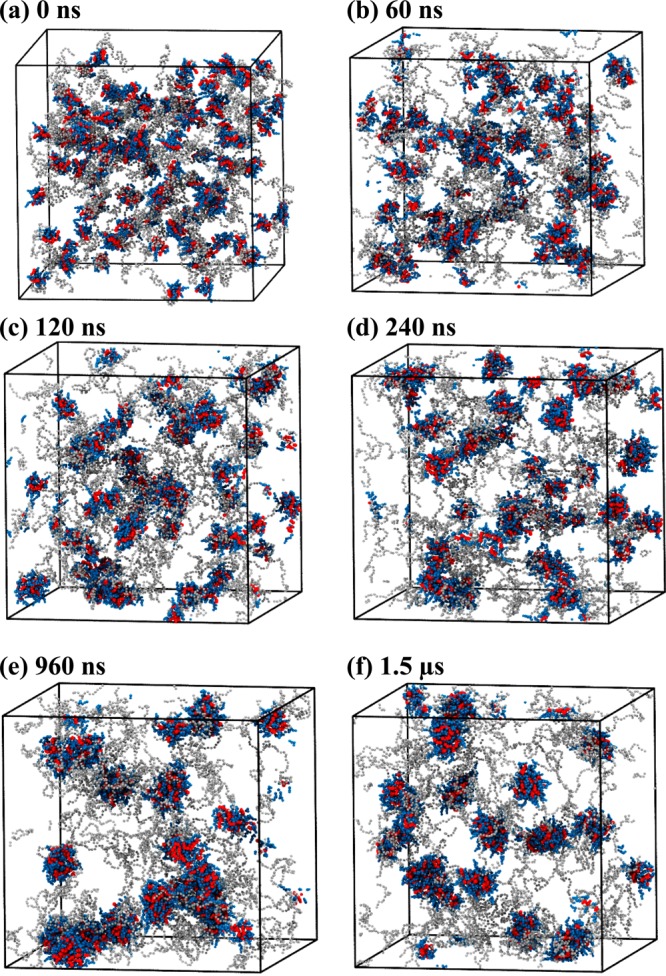
Snapshots of PEG3KCA8 telodendrimers (gray, blue, red) in a cubic simulation box at (a) 0 ns, (b) 60 ns, (c) 120 ns, (d) 240 ns, (e) 960 ns, and (f) 1.5 μs of molecular dynamics simulation. Water beads are not shown for clarity.
For PEG5KCA8 systems V and VI, telodendrimer aggregation was more pronounced than that for PEG3KCA8. Aggregates of 10–15 telodendrimers were formed within 60 ns (Figure 4a,b) from a randomly packed initial configuration. In the next 300–500 ns, the clusters coalesce to form stable spherical micelles that remain in dynamic equilibrium with the bulk (Figure 4) but the size of the micelles was stabilized.
Figure 4.
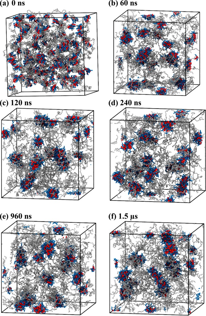
Snapshots of PEG5KCA8 telodendrimers (gray, blue, red) in a cubic simulation box at (a) 0 ns, (b) 60 ns, (c) 120 ns, (d) 240 ns, (e) 960 ns, and (f) 1.5 μs of molecular dynamics simulation. Water beads are not shown for clarity.
The average size of the clusters during the self-assembly is shown in Figure 5. The size distribution analysis of the micelles at 1.5 μs showed a narrow size distribution of 18 and 19 nm diameter in both simulations and experiments. Increasing the number of telodendrimers in the simulation box and the box size made a small difference in the optimal size of the micelle but the change is within the error bars of the calculations (Table 1), which again confirms the results shown in Table 2 for PEG2KCA4 micelles.
Figure 5.
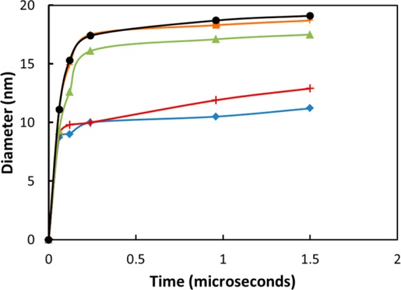
Micelle size as a function of time for (a) PEG2KCA4 (system I, blue, diamond), (b) PEG3KCA6 (system III, red, plus), (c) PEG3KCA8 (system IV, green, triangle), (d) PEG5KCA8 (system V, orange, square), and (e) PEG5KCA8 (system VI, black, circle).
Evaluation of the six telodendrimers molecules highlights the sensitivity of self-assembly to the number of CA groups and length of the PEG chain. Comparing systems II, V, and VI that have eight CA groups and 2K, 3K, and 5K PEG chains, respectively, shows the propensity of micelle formation with increase in chain length. The aggregation of the telodendrimers into micelles happens within 60–120 ns for PEG5KCA8 and PEG3KCA8; however, the short 2K PEG chain offsets the hydrophilic–hydrophobic ratio in the case of PEG2KCA8 telodendrimers and they fail to self-assemble as spherical micelles. Decreasing the number of CA groups to four or six does allow micelle formation if the hydrophilic PEG chain length is optimized in the 2–3 kDa range, but for drug delivery, longer PEG chain is preferable as it provides stealth to the encapsulated cargo and increases the circulation time of the nanocarrier in the blood. For this reason, we will focus on PEG5KCA8 and PEG3KCA8 telodendrimers for PTX drug loading simulations.
IV.B. Self-Assembly of Drug Loaded Telodendrimer Micelle
PTX drug loading capacity of telodendrimers was investigated in five systems, 5–36 w/w %, labeled as VIII–XII (Table 1). As before, telodendrimers and PTX molecules were randomly packed in the simulation cell and allowed to interact until the system attained dynamic equilibrium. To ensure that length of the periodic box did not bias the self-assembly and the size of drug loaded micelles, system VIII was simulated in boxes for different lengths (Table 2), and the average diameter of the micelles were comparable.
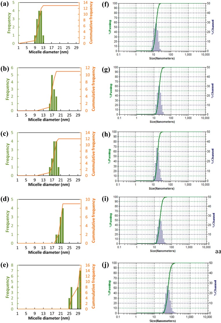
The time-lapsed snapshots of PEG5KCA8 with 17% (Figure 6) and 36% (Figure 7) PTX loading show aggregation of drug molecules with the CA head of the telodendrimers. The drug being hydrophobic forms clusters like oil droplets that interact with telodendrimers to form spherical micelles. Within 120 ns from the beginning of the simulation, clusters of 18–21 telodendrimers around PTX core is formed that continues to grow gradually until 900 ns. Figure 8a shows the size of the micelles as the telodendrimer–drug molecules self-assemble over time. The size distribution histogram analysis of the system showed consistent micelle sizes at 1 and 1.5 μs indicating that the system was in dynamic equilibrium (Figure 9). In system X, the drug molecules were incorporated into the micelle cores, and at 960 ns the snapshot (Figure 6e) shows few micelles with PTX drug molecules interacting with their shell. At 1.5 μs, the micelles are well-formed and only 68% of the drug molecules are encapsulated (Figure 8b). This shows a remarkable efficiency of PEG5KCA8 in encapsulating PTX molecules to form stable independent micelles with a well-defined geometry and narrow size distribution of 23.8 ± 3.5 nm, which is in agreement with experimental values of 19.0 ± 5.0 (Table 1). Additionally, the composition of the micelles was found to be uniform with 53 PTX molecules for 30 telodendrimers on an average (Table 1).
Figure 6.
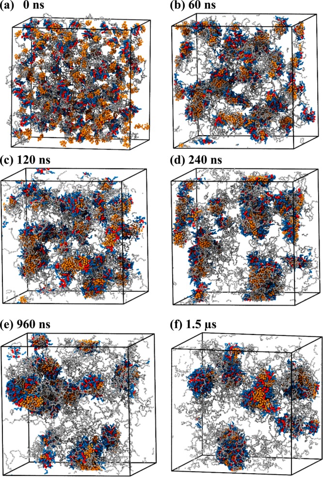
Snapshots of PTX (orange) and PEG5KCA8 telodendrimers (gray, blue, red) with 17% (w/w %) drug loading in simulation box at (a) 0 ns, (b) 60 ns, (c) 120 ns, (d) 240 ns, (e) 960 ns, and (d) 1.5 μs. Water beads are not shown for clarity.
Figure 7.
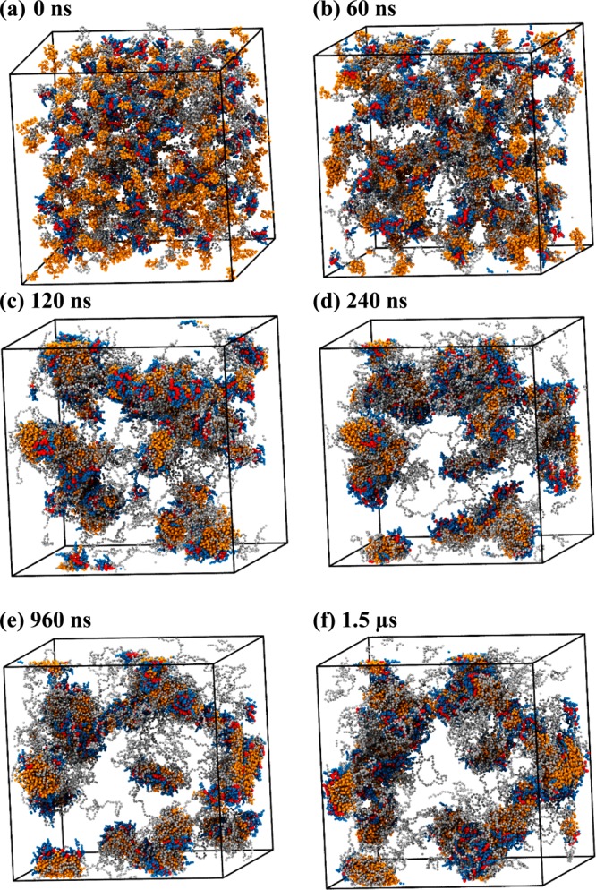
Snapshots of PTX (orange) and PEG5KCA8 telodendrimers (gray, blue, red) with 36% (w/w %) drug loading in simulation box at (a) 0 ns (b) 60 ns (c) 120 ns (d) 240 ns (e) 960 ns and (d) 1.5 μs. Water beads are not shown for clarity.
Figure 8.
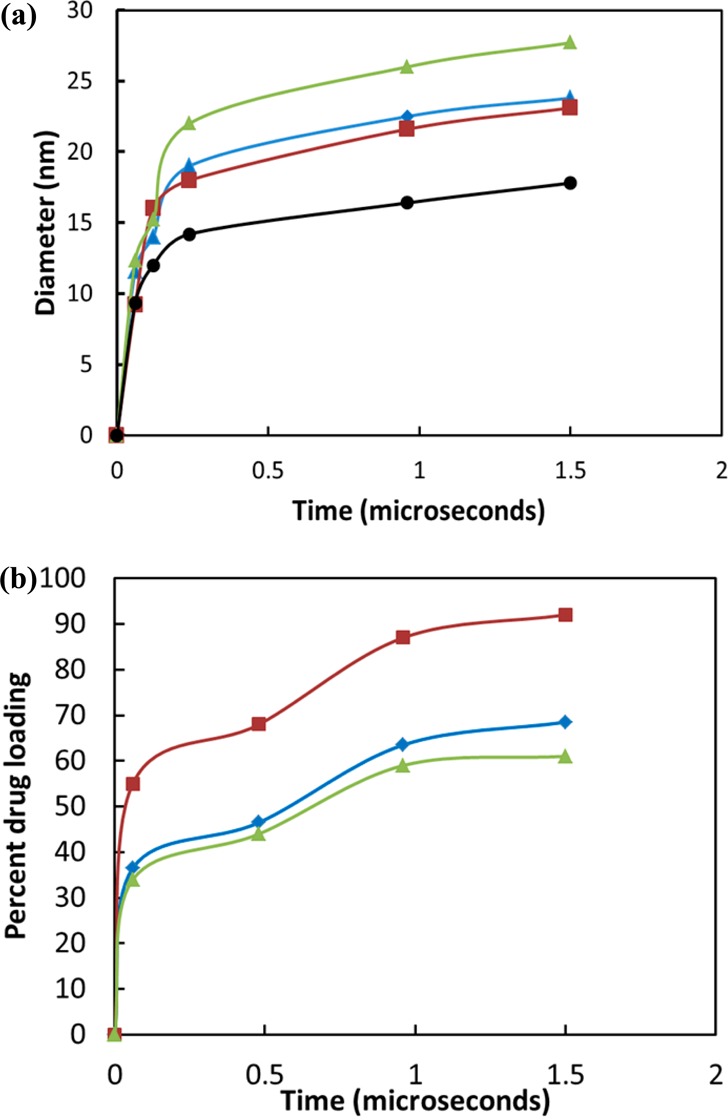
Properties of drug-loaded micelles as a function of time. (a) Micelle diameter (nm) as a function of time (μs) for (i) system VIII (black, circle), (ii) system IX (red, square), (iii) system X (blue, diamond), and (iv) system XI (green, triangle). (b) Drug encapsulation as a function of time during the self-assembly process for systems IX, X, and XI (same color scheme as in (a)).
Figure 9.
Size distribution of (a) PEG3KCA6, (b) PEG3KCA8, (c) PEG5KCA8, (d) PTX PEG5KCA8 17% (w/w %), and (e) PTX PEG5KCA8 36% (w/w %) obtained from simulations and corresponding experimental data and (f–j) measured by dynamic light scanning.
The simulations were repeated with lower (5%) and higher (25% and 36%) drug loading with the same number of initial telodendrimers. The encapsulation efficiency of the micelles decreases as the percentage of drug loading increases from 5 to 25% (Figure 8b); however, as expected, the micelle size increases with increase in drug loading. The computed micelle diameters are in excellent agreement with the experimental data (Table 1). The frequency distribution analysis shows a narrow micelle size distribution around 20–21 nm micelle for system X and a broader distribution for XI system ranging between 24 and 30 nm diameter.
In system XII, micelles formed much larger aggregates (Figure 7), and 27% of the drug molecules were not incorporated into the micelles. The size distribution analysis shows nonuniform micelles lacking the core–shell motif. As the amount of drug in the core increases, the telodendrimers are no longer able to shield the PTX core making the micelle unstable and leaky. Experimentally, the 36% (w/w) PTX loaded nanocarriers are excessively large with up to 58.0 ±15.0 nm in diameter, which happens due to aggregation of unstable micelles, as shown in Figure 7.
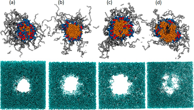
The cross-sectional views of the micelles and the surrounding water in Figure 10a–c show an overall spherical shape of the micelle. The drug molecules are encapsulated within the amphiphilic envelope of the CA groups of the telodendrimers. No water molecules were found in the core and the PEG chains form a spherical shell around the drug core. In contrast, the cross-sectional view of the micelle in Figure 10d shows the core filled with water and PTX drug exposed to the surrounding water. Additionally, reverse mapped analysis of the micelle shows hydrogen bonds are formed between the PTX core and water.
Figure 10.
Cross-sectional slices of telodendrimer micelles (orange, red, blue, and gray) and the surrounding water (light blue) for (a) 5%, (b) 17%, (c) 25%, and (d) 36% (% w/w) PTX loaded nanocarriers.
IV.C. Effect of Cholic Acid Facial Amphiphilicity
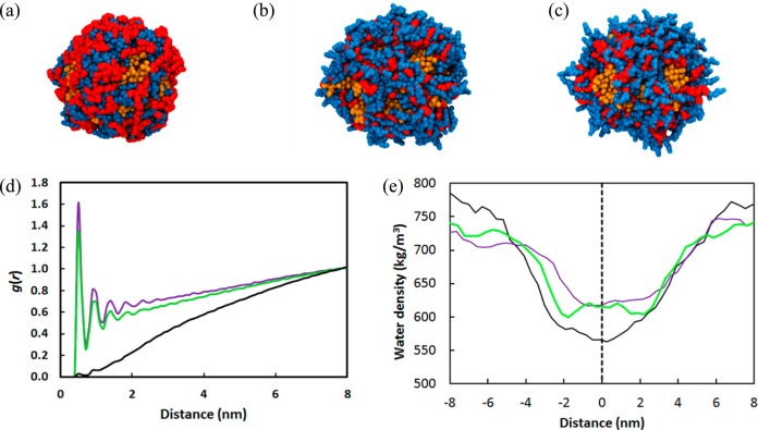
To test the role of facial amphiphilicity in enabling PEG5KCA8 telodendrimer to load PTX, we repeated system X two times with both CA faces either hydrophobic or hydrophilic, by changing the coarse grain bead type of the cholic acid faces to nonpolar (SC1) and polar (SP5), respectively. In both cases micelles were formed in the presence of PTX, but the systems showed strikingly distinct drug loading behaviors (Figure 11a–c). The hydrophobic cholic acids interact favorably with the hydrophobic PTX drug molecules forming a 9% more compact core (Figure 11a) and a low 0.34 nm2 solvent accessible surface area (SASA) value (Table 3). The gca-water(r) radial distribution function of the terminal CA bead with the water lacks any structured peaks indicating minimal interaction with the aqueous phase (Figure 11d). The hydrophobic CA provides a water repellent core that pushes the water away from micelle. The density profile of water along the length of the simulation box shows the low density profile of water surrounding the micelle core, which increases toward the edges of the box (Figure 11e).
Figure 11.
Comparison of PTX loaded micelle cores formed by (a) hydrophobic (b) amphiphilic and (c) hydrophilic forms of cholic acid. The CA (blue) and LYS (red) groups encapsulating the PTX drug (orange) molecules are shown but the PEG shell is not shown for clarity. Plots of (d) radial distribution function of cholic acid with water, and (e) water density along the length of the simulation box for hydrophilic (purple line), amphiphilic (green line), and hydrophobic (black) CAs. The dashed line shows the center of the micelle.
Table 3. Effect of Cholic Acid and Its Modified Forms on the Properties of the Paclitaxel Loaded Nanocarriers.
| diameter
(nm) |
no.
of H-bonds |
|||||
|---|---|---|---|---|---|---|
| cholic acid (CA) | PTX core | micelle | PTX | CA | PEO | SASA (nm2) |
| hydrophobic | 8.1 ± 0.1 | 19.5 ± 4.7 | 0 | 248 | 2783 | 0.3 |
| amphiphilic | 8.9 ± 0.2 | 23.8 ± 3.5 | 0 | 466 | 2884 | 2.1 |
| hydrophilic | 9.3 ± 0.4 | 24.9 ± 3.3 | 32 | 484 | 2884 | 10.4 |
In contrast, purely hydrophilic cholic acid telodendrimers do not form a stable micelle core and have a high 10.4 nm2 SASA. The micelle is loosely formed and the core is 18% larger in size than the hydrophobic core. The terminal hydrophilic beads of the CA groups pointed radially outward from the core (Figure 11c), and the gca-water(r) function of the CA beads showed well-defined water structure peaks with the surrounding water (Figure 11d). The density of water around the micelle was much higher 625–660 kg/m3 than the hydrophobic functionalized CA micelle (Figure 11e). Unlike the two modified forms of CA, the amphiphilic CA has all the desired properties of the core forming building block. The amphiphilic CA telodendrimers self-assemble in aqueous solutions both in presence and absence of PTX. The PTX core is effectively shielded from the surrounding water as evident from the relatively small SASA value of 2.1 nm2, while still maintaining the favorable interaction with the surrounding aqueous environment and water density of 600 kg/m3 which is close to the hydrophilic substituted CA micelle.
The gca-water(r) profile of amphiphilic CA shows similar peaks as the hydrophilic CA (Figure 11d). Overall, the amphiphilic CA is a superior building block compared to the pure hydrophilic and hydrophobic forms of CA when it comes to loading hydrophobic drugs in the core. The number of cholic acids in a telodendrimer significantly alters the stability and drug loading capacity of the micelle. It has been experimentally observed that telodendrimers with greater numbers of cholic acid, such as 10–16, tend to form larger micelles that are unstable and precipitate. In contrast, having four to six CAs leads to lower drug loading capabilities (<10% w/w), and their sizes range from 120 to 170 nm. An exception is PEG2KCA4 telodendrimer that forms stable nanocarriers with narrow size distribution 15.6 ± 3.3 at 20% (w/w) drug loading. This was confirmed both computationally and experimentally. Overall, having 8 CAs was found to be optimal for desired size distribution, maximum drug loading, and stability.
V. Conclusions
In this work, we have applied a multiscale computational approach, in conjunction with experiments to study the self-assembly of telodendrimers that form highly tunable micellar nanostructures, capable of efficient anticancer drug delivery. Telodendrimer building blocks include linear polyethylene glycol chain and dendritic cholic acid groups that are responsible for encapsulating the hydrophobic paclitaxel drug in the core of the nanocarrier. In general, optimizing the copolymer building blocks at the atomistic level is challenging, especially computationally because of the enormity of the micellar structures and the time scales required for self-assembly. To overcome this bottleneck, we applied a multiscale approach of coarse graining approach of the system that allowed us to track the self-assembly process of nanocarrier formation over microsecond time scales. Additionally, the reverse mapping protocol was developed to analyze the nanocarriers at the atomistic level. The results provided drug–telodendrimer micellar stoichiometry, cross-sectional view of the micelle, solvent accessible area, and hydrogen bonding, which are the quantities not available through experimental analysis. The computational and experimental results conclusively show that the hydrophobic–hydrophilic balance of telodendrimer is crucial for forming stable nanocarrier. Losing the balance resulted in less stable micelles with limited drug loading capacity or precipitation. For the systems studied here, telodendrimers with eight amphiphilic CA groups and five kDa PEG chain could encapsulate PTX drug up to 25% (w/w %). Furthermore, facial amphiphilicity cholic acid building block is critical in stabilizing paclitaxel-loaded micelle. Any modification to the cholic acid groups to either hydrophilic or hydrophobic caused the micelles to become unstable. Agreement between the computational and experimental results highlights the strengths of the multiscale approach and suggests that the multiscale methods are capable of capturing the long and short length scales that are important for nanocarrier design. The multiscale approach used in this work can be effectively utilized as a powerful prescreening tool in the process of discovery, development, and optimization of new drug delivery systems, reducing both the time and the cost of the process.
Acknowledgments
The authors thank XSEDE supercomputing facility for providing computational resources for some of the calculations. We also thank Syracuse University for the financial support of this project. The financial support for J.L. from NIH/NCI R01CA140449 is greatly acknowledged.
Supporting Information Available
GROMACS topology file for coarse grained PEG5KCA8 telodendrimer; atomistic and coarse grained structure of cholic acid; total energy versus time plot of PTX-PEG5KCA8 17% (w/w %) system; snapshot of reverse mapped PEG5KCA8 system in a cubic simulation box; reverse mapped PTX-PEG5KCA8 system with 17% (w/w %) drug loading in a simulation box; size distribution of PEG5KCA8 from simulations and experimental data; radial distribution functions of cholic acid beads. This material is available free of charge via the Internet at http://pubs.acs.org.
The authors declare no competing financial interest.
Funding Statement
National Institutes of Health, United States
Supplementary Material
References
- Gaucher G.; Dufresne M. H.; Sant V. P.; Kang N.; Maysinger D.; Leroux J. C. Block copolymer micelles: preparation, characterization and application in drug delivery. J. Controlled Release 2005, 109, 169–188. [DOI] [PubMed] [Google Scholar]
- Torchilin V. P. Micellar nanocarriers: Pharmaceutical perspectives. Pharm. Res. 2007, 24, 1–16. [DOI] [PubMed] [Google Scholar]
- Mu L.; Feng S. S. A novel controlled release formulation for the anticancer drug paclitaxel (Taxol (R)): PLGA nanoparticles containing vitamin E TPGS. J. Controlled Release 2003, 86, 33–48. [DOI] [PubMed] [Google Scholar]
- ten Tije A. J.; Verweij J.; Loos W. J.; Sparreboom A. Pharmacological effects of formulation vehicles — Implications for cancer chemotherapy. Clin. Pharmacokinet. 2003, 42, 665–685. [DOI] [PubMed] [Google Scholar]
- Feng S. S.; Mu L.; Win K. Y.; Huang G. F. Nanoparticles of biodegradable polymers for clinical administration of paclitaxel. Curr. Med. Chem. 2004, 11, 413–424. [DOI] [PubMed] [Google Scholar]
- Liu Z.; Chen K.; Davis C.; Sherlock S.; Cao Q.; Chen X.; Dai H. Drug delivery with carbon nanotubes for in vivo cancer treatment. Cancer Res. 2008, 68, 6652–6660. [DOI] [PMC free article] [PubMed] [Google Scholar]
- Nishiyama N.; Kataoka K. Current state, achievements, and future prospects of polymeric micelles as nanocarriers for drug and gene delivery. Pharmacol. Ther. 2006, 112, 630–648. [DOI] [PubMed] [Google Scholar]
- Ganta S.; Devalapally H.; Shahiwala A.; Amiji M. A review of stimuli-responsive nanocarriers for drug and gene delivery. J. Controlled Release 2008, 126, 187–204. [DOI] [PubMed] [Google Scholar]
- Blanco E.; Hsiao A.; Mann A. P.; Landry M. G.; Meric-Bernstam F.; Ferrari M. Nanomedicine in cancer therapy: Innovative trends and prospects. Cancer Sci. 2011, 102, 1247–1252. [DOI] [PMC free article] [PubMed] [Google Scholar]
- Xu Q.; Liu Y.; Su S.; Li W.; Chen C.; Wu Y. Anti-tumor activity of paclitaxel through dual-targeting carrier of cyclic RGD and transferrin conjugated hyperbranched copolymer nanoparticles. Biomaterials 2012, 33, 1627–1639. [DOI] [PubMed] [Google Scholar]
- Cammas S.; Suzuki K.; Sone C.; Sakurai Y.; Kataoka K.; Okano T. Thermo-responsive polymer nanoparticles with a core-shell micelle structure as site-specific drug carriers. J. Controlled Release 1997, 48, 157–164. [Google Scholar]
- Rapoport N. Physical stimuli-responsive polymeric micelles for anti-cancer drug delivery. Prog. Polym. Sci. 2007, 32, 962–990. [Google Scholar]
- Kruse H.; McMaster P. D. The distribution and storage of blue antigenic azoproteins in the tissues of mice. J. Exp. Med. 1949, 90, 425. [DOI] [PMC free article] [PubMed] [Google Scholar]
- Song C. X.; Labhasetwar V.; Murphy H.; Qu X.; Humphrey W. R.; Shebuski R. J.; Levy R. J. Formulation and characterization of biodegradable nanoparticles for intravascular local drug delivery. J. Controlled Release 1997, 43, 197–212. [Google Scholar]
- Rosler A.; Vandermeulen G. W. M.; Klok H. A. Advanced drug delivery devices via self-assembly of amphiphilic block copolymers. Adv. Drug Delivery Rev. 2001, 53, 95–108. [DOI] [PubMed] [Google Scholar]
- Xu Y.; Ma R.; Zhang Z.; He H.; Wang Y.; Qu A.; An Y.; Zhu X. X.; Shi L. Complex micelles with a responsive shell for controlling of enzymatic degradation. Polymer 2012, 53, 3559–3565. [Google Scholar]
- Ruan G.; Feng S. S. Preparation and characterization of poly(lactic acid)-poly(ethylene glycol)-poly(lactic acid) (PLA-PEG-PLA) microspheres for controlled release of paclitaxel. Biomaterials 2003, 24, 5037–5044. [DOI] [PubMed] [Google Scholar]
- Chen M.; Ouyang H.; Zhou S.; Li J.; Ye Y. PLGA-nanoparticle mediated delivery of anti-OX40 monoclonal antibody enhances anti-tumor cytotoxic T cell responses. Cell. Immunol. 2014, 287, 91–99. [DOI] [PubMed] [Google Scholar]
- Li J. T.; Caldwell K. D.; Rapoport N. Surface-properties of pluronic-coated polymeric colloids. Langmuir 1994, 10, 4475–4482. [Google Scholar]
- Stapert H. R.; Nishiyama N.; Jiang D. L.; Aida T.; Kataoka K. Polyion complex micelles encapsulating light-harvesting ionic dendrimer zinc porphyrins. Langmuir 2000, 16, 8182–8188. [Google Scholar]
- Lukyanov A. N.; Torchilin V. P. Micelles from lipid derivatives of water-soluble polymers as delivery systems for poorly soluble drugs. Adv. Drug Delivery Rev. 2004, 56, 1273–1289. [DOI] [PubMed] [Google Scholar]
- Talelli M.; Morita K.; Rijcken C. J. F.; Aben R. W. M.; Lammers T.; Scheeren H. W.; van Nostrum C. F.; Storm G.; Hennink W. E. Synthesis and characterization of biodegradable and thermosensitive polymeric micelles with covalently bound doxorubicin-glucuronide prodrug via click chemistry. Bioconjugate Chem. 2011, 22, 2519–2530. [DOI] [PubMed] [Google Scholar]
- Rezaei S. J. T.; Nabid M. R.; Niknejad H.; Entezami A. A. Multifunctional and thermoresponsive unimolecular micelles for tumor-targeted delivery and site-specifically release of anticancer drugs. Polymer 2012, 53, 3485–3497. [Google Scholar]
- Burnham N. L. Polymers for delivering peptides and proteins. Am. J. Hosp. Pharm. 1994, 51, 210–218. [PubMed] [Google Scholar]
- Cai T.; Marquez M.; Hu Z. Monodisperse thermoresponsive microgels of poly(ethylene glycol) analogue-based biopolymers. Langmuir 2007, 23, 8663–8666. [DOI] [PubMed] [Google Scholar]
- Veronese F. M.; Pasut G. PEGylation, successful approach to drug delivery. Drug Discovery Today 2005, 10, 1451–1458. [DOI] [PubMed] [Google Scholar]
- Xiao K.; Luo J.; Fowler W. L.; Li Y.; Lee J. S.; Xing L.; Cheng R. H.; Wang L.; Lam K. S. A self-assembling nanoparticle for paclitaxel delivery in ovarian cancer. Biomaterials 2009, 30, 6006–6016. [DOI] [PMC free article] [PubMed] [Google Scholar]
- Luo J.; Xiao K.; Li Y.; Lee J. S.; Shi L.; Tan Y.-H.; Xing L.; Cheng R. H.; Liu G.-Y.; Lam K. S. Well-defined, size-tunable, multifunctional micelles for efficient paclitaxel delivery for cancer treatment. Bioconjugate Chem. 2010, 21, 1216–1224. [DOI] [PMC free article] [PubMed] [Google Scholar]
- Xiao K.; Luo J.; Li Y.; Lee J. S.; Fung G.; Lam K. S. PEG-oligocholic acid telodendrimer micelles for the targeted delivery of doxorubicin to B-cell lymphoma. J. Controlled Release 2011, 155, 272–281. [DOI] [PMC free article] [PubMed] [Google Scholar]
- Xiao W.; Luo J.; Jain T.; Riggs J. W.; Tseng H. P.; Henderson P. T.; Cherry S. R.; Rowland D.; Lam K. S. Biodistribution and pharmacokinetics of a telodendrimer micellar paclitaxel nanoformulation in a mouse xenograft model of ovarian cancer. Int. J. Nanomed. 2012, 7, 1587–1597. [DOI] [PMC free article] [PubMed] [Google Scholar]
- He W.; Luo J.; Bourguet F.; Xing L.; Yi S. K.; Gao T.; Blanchette C.; Henderson P. T.; Kuhn E.; Malfatti M.; Murphy W. J.; Cheng R. H.; Lam K. S.; Coleman M. A. Controlling the diameter, monodispersity, and solubility of ApoA1 nanolipoprotein particles using telodendrimer chemistry. Protein Sci. 2013, 22, 1078–1086. [DOI] [PMC free article] [PubMed] [Google Scholar]
- Hawker C. J.Dendritic and hyperbranched macromolecules — Precisely controlled macromolecular architectures. In Macromolecular Architectures; Hilborn J. G., Ed.; Springer-Verlag: Berlin, 1999; Vol. 147, pp 113–160. [Google Scholar]
- Huczko A. Template-based synthesis of nanomaterials. Appl. Phys. A: Mater. Sci. Process. 2000, 70, 365–376. [Google Scholar]
- Lehn J. M. Supramolecular chemistry: From molecular information towards self-organization and complex matter. Rep. Prog. Phys. 2004, 67, 249–265. [Google Scholar]
- Shi C.; Yuan D.; Nangia S.; Xu G.; Lam K. S.; Luo J. A structure–property relationship study of the well-defined telodendrimers to improve hemocompatibility of nanocarriers for anticancer drug delivery. Langmuir 2014, 30, 6878–6888. [DOI] [PMC free article] [PubMed] [Google Scholar]
- Safaei-Ghomi J.; Ghiaci M.; Sadeghi Z. Theoretical evaluation of the nanocarrier properties of hyperbranched oligo (ethyleneimine) cascade generations 1-5. Dig. J. Nanomater. Biostruct. 2010, 5, 535–544. [Google Scholar]
- Wan L.; Zhang X.; Pooyan S.; Palombo M. S.; Leibowitz M. J.; Stein S.; Sinko P. J. Optimizing size and copy number for PEG-fMLF (N-formyl-methionyl-leucyl-phenylalanine) nanocarrier uptake by macrophages. Bioconjugate Chem. 2008, 19, 28–38. [DOI] [PMC free article] [PubMed] [Google Scholar]
- Lee H.; de Vries A. H.; Marrink S. J.; Pastor R. W. A coarse-grained model for polyethylene oxide and polyethylene glycol: Conformation and hydrodynamics. J. Phys. Chem. B 2009, 113, 13186–13194. [DOI] [PMC free article] [PubMed] [Google Scholar]
- Yesylevskyy S. O.; Schafer L. V.; Sengupta D.; Marrink S. J. Polarizable water model for the coarse-grained martini force field. PLoS Comput. Biol. 2010, 6, e1000810. [DOI] [PMC free article] [PubMed] [Google Scholar]
- de Jong D. H.; Singh G.; Bennett W. F. D.; Arnarez C.; Wassenaar T. A.; Schafer L. V.; Periole X.; Tieleman D. P.; Marrink S. J. Improved parameters for the martini coarse-grained protein force field. J. Chem. Theory Comput. 2013, 9, 687–697. [DOI] [PubMed] [Google Scholar]
- Peng L. L. X.; Yu L.; Howell S. B.; Gough D. A. Aggregation properties of a polymeric anticancer therapeutic: A coarse-grained modeling study. J. Chem. Inf. Model. 2011, 51, 3030–3035. [DOI] [PubMed] [Google Scholar]
- Peng L. X.; Ivetac A.; Chaudhari A. S.; Van S.; Zhao G.; Yu L.; Howell S. B.; McCammon J. A.; Gough D. A. Characterization of a clinical polymer-drug conjugate using multiscale modeling. Biopolymers 2010, 93, 936–951. [DOI] [PMC free article] [PubMed] [Google Scholar]
- Nangia S.; Sureshkumar R. Effects of nanoparticle charge and shape anisotropy on translocation through cell membranes. Langmuir 2012, 28, 17666–17671. [DOI] [PubMed] [Google Scholar]
- Sangwai A. V.; Sureshkumar R. Coarse-grained molecular dynamics simulations of the sphere to rod transition in surfactant micelles. Langmuir 2011, 27, 6628–6638. [DOI] [PubMed] [Google Scholar]
- Marrink S. J.; Risselada H. J.; Yefimov S.; Tieleman D. P.; de Vries A. H. The MARTINI force field: Coarse grained model for biomolecular simulations. J. Phys. Chem. B 2007, 111, 7812–7824. [DOI] [PubMed] [Google Scholar]
- Monticelli L.; Kandasamy S. K.; Periole X.; Larson R. G.; Tieleman D. P.; Marrink S. J. The MARTINI coarse-grained force field: Extension to proteins. J. Chem. Theory Comput. 2008, 4, 819–834. [DOI] [PubMed] [Google Scholar]
- Barril X.; Javier Luque F. Molecular simulation methods in drug discovery: A prospective outlook. J. Comput.-Aided Mol. Des. 2012, 26, 81–86. [DOI] [PubMed] [Google Scholar]
- Borhani D. W.; Shaw D. E. The future of molecular dynamics simulations in drug discovery. J. Comput.-Aided Mol. Des. 2012, 26, 15–26. [DOI] [PMC free article] [PubMed] [Google Scholar]
- Crook N.; Alper H. S. Model-based design of synthetic, biological systems. Chem. Eng. Sci. 2013, 103, 2–11. [Google Scholar]
- Parenti M. D.; Rastelli G. Advances and applications of binding affinity prediction methods in drug discovery. Biotechnol. Adv. 2012, 30, 244–250. [DOI] [PubMed] [Google Scholar]
- Doruker P.; Mattice W. L. Reverse mapping of coarse-grained polyethylene chains from the second nearest neighbor diamond lattice to an atomistic model in continuous space. Macromolecules 1997, 30, 5520–5526. [Google Scholar]
- Spyriouni T.; Tzoumanekas C.; Theodorou D.; Mueller-Plathe F.; Milano G. Coarse-grained and reverse-mapped united-atom simulations of long-chain atactic polystyrene melts: Structure, thermodynamic properties, chain conformation, and entanglements. Macromolecules 2007, 40, 3876–3885. [Google Scholar]
- Wassenaar T. A.; Pluhackova K.; Boeckmann R. A.; Marrink S. J.; Tieleman D. P. Going backward: A flexible geometric approach to reverse transformation from coarse grained to atomistic models. J. Chem. Theory Comput. 2014, 10, 676–690. [DOI] [PubMed] [Google Scholar]
- Ackland G. J.; D’Mellow K.; Daraszewicz S. L.; Hepburn D. J.; Uhrin M.; Stratford K. The MOLDY short-range molecular dynamics package. Comput. Phys. Commun. 2011, 182, 2587–2604. [Google Scholar]
- Okumura H.; Itoh S. G.; Ito A. M.; Nakamura H.; Fukushima T. Manifold correction method for the Nosé–Hoover and Nosé–Poincare molecular dynamics simulations. J. Phys. Soc. Jpn. 2014, 83, 024003. [Google Scholar]
- Patra P. K.; Bhattacharya B. A deterministic thermostat for controlling temperature using all degrees of freedom. J. Chem. Phys. 2014, 140, 064106. [DOI] [PubMed] [Google Scholar]
- Brooks B. R.; B C. L. III; M A. D. Jr; Nilsson L.; Petrella R. J.; Roux B.; Won Y.; Archontis G.; Bartels C.; Boresch S.; Caflisch A.; Caves L.; Cui Q.; Dinner A. R.; Feig M.; Fischer S.; Gao J.; Hodoscek M.; Im W.; Kuczera K.; Lazaridis T.; Ma J.; Ovchinnikov V.; Paci E.; Pastor R. W.; Post C. B.; Pu J. Z.; Schaefer M.; Tidor B.; Venable R. M.; Woodcock H. L.; Wu X.; Yang W.; York D. M.; Karplus M. CHARMM: The biomolecular simulation program. J. Comput. Chem. 2009, 30, 1545–1614. [DOI] [PMC free article] [PubMed] [Google Scholar]
- Wang Y.; Teitel S.; Dellago C. Melting of icosahedral gold nanoclusters from molecular dynamics simulations. J. Chem. Phys. 2005, 122, 214722. [DOI] [PubMed] [Google Scholar]
- Vuorela T.; Catte A.; Niemelä P. S.; Hall A.; Hyvönen M. T.; Marrink S.-J.; Karttunen M.; Vattulainen I. Role of lipids in spheroidal high density lipoproteins. PLoS Comput. Biol. 2010, 6, e1000964. [DOI] [PMC free article] [PubMed] [Google Scholar]
Associated Data
This section collects any data citations, data availability statements, or supplementary materials included in this article.


