Abstract
Purpose:
MRI guided radiotherapy is a rapidly growing field; however, current electron accelerators are not designed to operate in the magnetic fringe fields of MRI scanners. As such, current MRI-Linac systems require magnetic shielding, which can degrade MR image quality and limit system flexibility. The purpose of this work was to develop and test a novel medical electron accelerator concept which is inherently robust to operation within magnetic fields for in-line MRI-Linac systems.
Methods:
Computational simulations were utilized to model the accelerator, including the thermionic emission process, the electromagnetic fields within the accelerating structure, and resulting particle trajectories through these fields. The spatial and energy characteristics of the electron beam were quantified at the accelerator target and compared to published data for conventional accelerators. The model was then coupled to the fields from a simulated 1 T superconducting magnet and solved for cathode to isocenter distances between 1.0 and 2.4 m; the impact on the electron beam was quantified.
Results:
For the zero field solution, the average current at the target was 146.3 mA, with a median energy of 5.8 MeV (interquartile spread of 0.1 MeV), and a spot size diameter of 1.5 mm full-width-tenth-maximum. Such an electron beam is suitable for therapy, comparing favorably to published data for conventional systems. The simulated accelerator showed increased robustness to operation in in-line magnetic fields, with a maximum current loss of 3% compared to 85% for a conventional system in the same magnetic fields.
Conclusions:
Computational simulations suggest that replacing conventional DC electron sources with a RF based source could be used to develop medical electron accelerators which are robust to operation in in-line magnetic fields. This would enable the development of MRI-Linac systems with no magnetic shielding around the Linac and reduce the requirements for optimization of magnetic fringe field, simplify design of the high-field magnet, and increase system flexibility.
Keywords: MRI linac, linear accelerator, finite element modelling, electron beam, RF modelling
1. INTRODUCTION
Several research groups are developing coupled medical linear accelerator and magnet resonance imaging devices (MRI-Linac). The goal of these efforts is to enable in-room MRI for anatomic and physiological treatment adaptation and response monitoring.1 Integration of these two devices is challenging, as both produce external electromagnetic fields, and the combined device must function within the net electromagnetic field environment. The resultant electromagnetic coupling of the two devices results in many engineering and design challenges, one of which is the production of an acceptable treatment beam—the subject of this paper.
Typical treatment beam requirements for photon radiation therapy are beam energy of 4–20 MV and dose rate on the order of 500 cGy/min at the treatment isocenter.2 A simple medical linear accelerator (Linac) can be considered to comprise of two subcomponents: a thermionic electrostatic electron gun which serves as the source of the beam, and a series of coupled resonant radiofrequency (RF) cavities which are used to accelerate the electron beam to MeV energies. The accelerated electron beam is then typically collided with a tungsten target to produce a bremsstrahlung photon beam. It is challenging to operate a Linac in MRI-Linac systems, as moving electrons are subjected to Lorentz forces from the magnetic fields of the MRI scanner. If not compensated for, this can cause severe aberrations in the Linac behavior, up to and including complete beam loss.3,4 The exact behavior of a linear accelerator when subjected to external magnetic fields depends on the magnitude and orientation of those fields. As such, the orientation of the accelerator with respect to the MRI scanner becomes important. Two orientations are feasible; the in-line setup, in which electrons are accelerated in the same direction as the magnetic field of the MRI-scanner, and the perpendicular setup, in which the electrons are accelerated perpendicular to the magnetic field. Each of these configurations has unique advantages and disadvantages associated with it which have been discussed elsewhere5—however, if one considers particle acceleration in isolation, then the in-line configuration is indisputably the superior option. This is because magnetic force on a charged particle is minimized when the particle is travelling in the same direction as the magnetic field lines (to be precise, the magnitude of magnetic force is zero when a particle travels parallel to a magnetic field, and maximal when it travels perpendicular).
The effects of both in-line and perpendicular magnetic fields on linear accelerator operation have previously been studied via computational simulations. For the perpendicular case, total beam loss occurred at 14 G, and 45% at 6 G.3,4 This means that in order to produce a treatment beam for the perpendicular orientation, the Linac must be operated in a near zero field environment. This can be achieved by modifying the magnet and magnetically shielding the Linac (Ref. 6)—however, MRI magnet design (and redesign) is not a trivial task, and magnetic shielding perturbs the field homogeneity in the imaging volume of the MRI scanner. For the in-line case, the maximum beam loss was 79%, which occurred at a field of 600 G.3,7 It was also shown that the effect of magnetic fields on the electron accelerator is nearly entirely on the electron gun—that is, operation of the accelerating cavities is largely unaffected.7,8 As such, to produce a treatment beam in the in-line orientation, the only component which needs to be customized is the electron gun. Two solutions for operating the electron gun in in-line magnetic fields have been proposed. The first is to redesign the optics of the electron gun taking the presence of in-line magnetic fields into account such that the modified gun functions within these fields.8 The second is to place magnetic shielding around the gun such that the field is reduced enough that acceptable gun performance is obtained.9 Both these approaches were shown to be very effective, however, both have drawbacks. Redesign of the gun optics requires a bespoke gun design for each different field it is to be used in. The published solution operates optimally only in the relatively high field of 1000 G or higher, and it is not clear if acceptable solutions of this nature exist at lower field strengths. The alternative, ferromagnetic shielding, causes distortion in the imaging field of the MRI scanner. This distortion can be corrected up to a point, as evidenced by current first generation MRI-Linac systems which successfully utilize magnetic shielding for either the electron gun or the entire Linac.1 However, for higher field strengths and smaller source to isocenter distances (SIDs), this becomes more difficult. It also limits the flexibility one has to compensate for other components which can cause magnetic distortion or require shielding, such as multileaf collimators.10,11
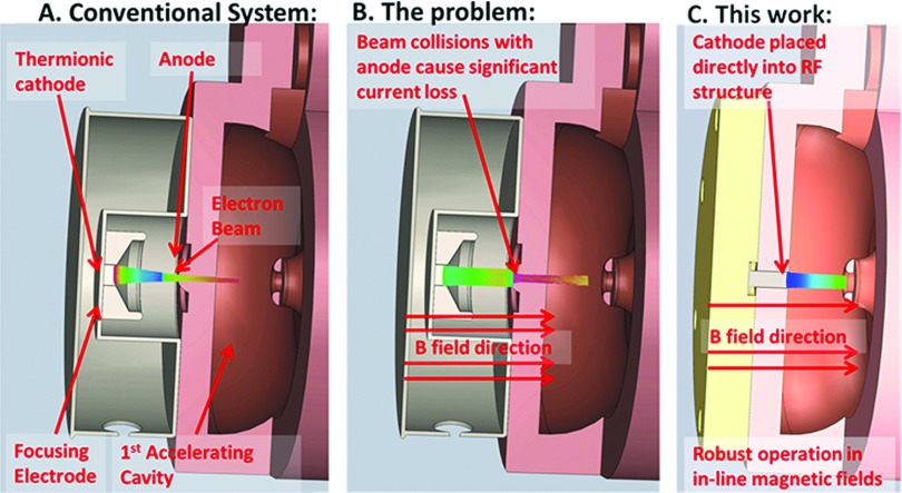
The ideal accelerator for in-line MRI-Linac systems would be robust to operation in a range of field strengths without magnetic shielding. A solution which could meet these criteria and that has not previously been explored is a RF electron gun based system. As the name implies, instead of the steady state fields used to produce an electron beam in conventional systems, RF electron guns utilize RF fields (Fig. 1). RF guns are widely used in other particle accelerator fields, for instance, as injectors to synchrotron beams.12 A RF gun based accelerator has two theoretical advantages over a DC based gun setup for MRI-Linac systems. (1) The beam is accelerated to relativistic velocities over a much shorter distance, resulting in a “stiffer” electron beam which is more difficult to bend, and (2) the cathode is subjected to much higher electric fields, which could reduce the need for transverse beam focusing—the main problem with conventional electron gun operation in in-line MRI-Linac systems.8 The purpose of this paper was to investigate these hypothetical advantages, and determine if a RF-gun based accelerator could produce a beam suitable for radiotherapy treatments.
FIG. 1.
(A) Conventional medical electron accelerator utilizing a steady state stream of electrons, however, (B) performance is compromised in in-line MRI-Linac systems. (C) In this work, we are proposing a novel electron accelerator utilizing a RF electron source which is robust to operation in magnetic fields.
2. METHODS AND MATERIALS
Computational simulations were utilized to investigate the behavior of a RF-gun based accelerator in in-line magnetic fields.
2.A. Model of thermionic emission
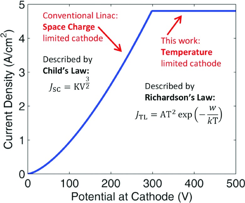
In conventional medical DC electron guns, a relatively low (kilovoltage) electrostatic field is applied to a thermionic cathode, resulting in space charge limited thermionic emission (the space charge of the beam limits the emitted current). Space charge limited emission is described by Child’s law [Eq. (1), in which K is a geometry dependent constant, and V is the electric potential at the cathode]
| (1) |
| (2) |
| (3) |
In the proposed configuration, the megavoltage electric field at the cathode is constantly changing as the electric field oscillates back and forth. Half the time no current will be emitted at all as the electric field is pointing in the wrong direction. For the other half, current emission is modeled using Richardson’s law for temperature limited thermionic emission [Eq. (2), Fig. 2], which describes the current extracted from a thermionic cathode assuming no space charge effects. In Eq. (1), w is the work function, T is temperature, and kB is Boltzman’s constant. This emission model is appropriate as the electric field in the RF cavity is hundreds of times higher than that in a DC electron gun, and temperature limited emission will dominate over space charge limited emission. An estimate of the total space charge limited contribution to the current can be obtained as follows: an accelerating RF pulse is defined by an input value for the peak RF field at the cathode. The point at which the cathode becomes temperature limited is then calculated; i.e., where JSC [Eq. (1)] > JTL [Eq. (2)]. The remainder of the pulse, which is considered space charge limited, is spilt into 10 bins, and in each bin the space charge limited current is calculated according to Eq. (1). The electric field is converted to potential difference for Child’s law using V = E ⋅ d, where d was chosen as 0.5 mm—a typical value for this kind of calculation. Using a value of 4 MV/m for peak field at the cathode, we estimate space charge limited emission will account for less than 5% of the emitted current. As will be seen in Sec. 3.B, 4 MV/m is a very conservative value. Higher fields further limit the impact of space charge. The values used in Richardson’s equation are shown in Table I, and match commercially available cathodes and experimental observations.13–15
FIG. 2.
Theoretical current extracted from a thermionic cathode versus potential difference. Note that the potential here includes the field of the extracted beam itself, and is assessed at a distance 0.5 mm from the cathode.
TABLE I.
Parameter values used in Richardson’s equation [Eq. (2)].
| Parameter | Value |
|---|---|
| A | 60 A/(cm2 ⋅ K) |
| T | 1245 K |
| w | 1.8 eV |
The transverse RMS emittance of the beam is often used as a figure of merit to quantify electron beam quality.16 For a thermionic cathode, the intrinsic, or thermal RMS emittance is given by Eq. (3) and is generally considered a lower bound on what can be practically achieved (rc refers to cathode radius, c the speed of light, and m0 the electron rest mass).16,17
2.B. Radiofrequency field calculation
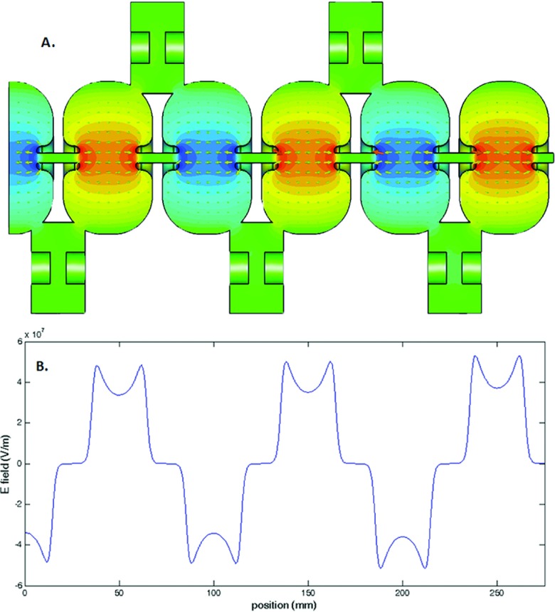
The next step was to calculate the RF fields to which the electrons will be subject while in the accelerating structure. We have utilized the basic S band cavity design presented by St. Aubin.18 This basic structure was staggered to develop a RF structure with five full accelerating cavities and one half cavity (Fig. 4). The fields within the cavities are solved using an eigenmode solver (CST, Darmstadt, Germany). The solver is based on the finite element method and utilizes a tetrahedral mesh with quadratic shape functions. An adaptive meshing strategy was utilized such that the discretization error in the frequency of the returned solution was less than 0.5 MHz. In order to minimize computational cost, a lossless eigenmode solver was utilized, which assumes perfect conductivity at all boundaries—a reasonable approximation for copper. The losses in the waveguide were calculated as a postprocessing step, which uses perturbation theory based on the magnetic field distribution at the walls. A conductivity of 5.8 × 10⁷ S/m (copper) was used. Further details on this method can be found in Ref. 19. A small ring like structure was added around the cathode in order to increase the radial focusing fields at the point of emission.
FIG. 4.
2.C. Particle trajectories
In order to calculate the particle trajectories, the RF fields from Sec. 2.B were imported into a particle in cell (PIC) solver (CST, Darmstadt, Germany) as ASCII files. The electric fields in the central region where the radial coordinate is less than 5 mm were sampled on a 0.1 mm Cartesian grid, whilst all other fields were sampled on a 1 mm grid. The resulting ASCII data took up around 6 Gb of disk space. The PIC solver is a fully integrated solution which incorporates space charge and wake field effects of the electron beam based on the finite integration technique (FIT), a formulation of the finite difference time domain (FDTD) method. Exactly the same geometry as in Sec. 2.B is used. The waveguide structure was discretized into 4.97 × 10⁶ hexahedral mesh cells. The electron source was defined based on the data from Sec. 2.A. Particle tracking was carried out over a time period of 1850 ps, representing around six RF cycles and two full electron bunches at the target plane. Rather than explicitly simulate each individual electron trajectory, electrons are grouped into macro particles. Each macro particle in this work represented around 200 electrons, and around three million macro particles reached the target in each simulation.
2.D. Beam assessment at the target
In order to assess the performance of the RF gun based accelerator, a beam monitor was placed at the exit of the simulation; particle information was scored as it crossed this monitor and exported to matlab for further analysis. The mean current, spatial, and energy distributions were evaluated to assess suitability of the beam for radiotherapy treatments. The normalized emittance at the target was calculated using Eq. (4), where x is the x coordinate, and px is the scaled momentum defined using the special relativity parameters such that px = γβx.16 Note that we calculate normalized emittance instead of the geometric emittance which has been used in previous recent publications in this journal.3,8,9,18,20,21 This is because the former quantity is a more appropriate and robust metric in instances where the beam energy is changing.16,22 If it is assumed that the relativistic γ and β distributions are single valued, normalized emittance can be also described as εN = εGβγ16 where εG is the geometric emittance which has been utilized in other recent publications.8,18,20
| (4) |
2.E. Back-bombardment power
An issue for all microwave accelerators which utilize a thermionic cathode is back-bombardment. This refers to electrons which are accelerated back toward the cathode, where they deposit unwanted power. This has two effects—first, it can damage the cathode and reduce its lifetime. Second, whilst the RF is on (∼5 μs in medical systems), the temperature of the cathode can be expected to rise steadily at a rate dependent on the power being delivered by back accelerated electrons.2,17,23 As such, back-bombardment is one of the principal effects which limit the achievable pulse length in thermionic guns used in both accelerator physics and in therapeutic systems. Conventional DC medical electron guns can be expected to have two advantages compared to the RF type cathode described here when considering back-bombardment. First, because they are operated in a space charge limited mode of emission (as opposed to temperature limited) the impact of additional heating during the pulse should be smaller. Second, any electron striking a DC cathode has to first navigate the anode drift tube and overcome the DC electric potential of the electron gun—meaning a cathode in a DC system has inherently greater protection from back-bombardment.
In order to quantify the extent of back-bombardment occurring in the proposed design, the back accelerated electrons striking the cathode plane in the simulation described in Sec. 2.C were exported to matlab for further analysis. In order to compare this to a conventional system, the RF source from Sec. 2.A was replaced with a DC source exported from an Opera electron gun simulation which has been previously described.8,21 The particles striking the wall of the first cavity of this simulation were imported into a separate PIC simulation which incorporated DC electron gun geometry along with the associated electrostatic field, and the electrons reaching the DC cathode were exported to matlab. As will be seen in Sec. 3.D, it takes some time for back-bombardment power to reach a steady state, so the simulation time was extended to 4000 ps for these simulations.
2.F. Performance in magnetic fields
In order to assess the performance of the RF gun accelerator in the presence of in-line magnetic fields, the particle in cell model from Sec. 2.C was coupled to a previously published model of a 1 T MRI magnet.10 This magnet is being constructed for the Australian MRI-Linac program.5 Since this field is axially symmetric in the in-line orientation, it can be characterized by the central axial field as outlined in Ref. 8. This field expansion is accurate to within a few gauss within the 2.5 mm radius beam line of the present accelerator structure. CST contains a built-in interface for adding a magnetic field in this manner which was utilized. The simulation was repeated for cathode to isocenter distances from 1 to 2.3 m in 0.1 m steps; the magnetic field at the cathode ranged from 141 to 2186 G over this range. For each step, the beam assessment was repeated. Note that the SID is approximately 300 mm smaller than the cathode to isocenter distance.
3. RESULTS
3.A. Model of thermionic emission
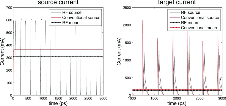
Based on Eq. (2), a cathode of radius 2 mm and work function 1.8 eV operated at a temperature of 1245 K will emit a current of 600 mA in the temperature limited regime. These values are all well within the capabilities of modern tungsten dispenser cathodes.13 Figure 3 shows a plot of the net current passing through a plane placed 1 mm in front of the start of the accelerating waveguide and at a plane at the end of the accelerating waveguide for the RF based electron source and a DC based electron source. The conventional DC source modeled here is the diode gun published by St. Aubin21 and frequently utilized in publications in this area.8,9,20 It can be seen that whilst the source currents of the two electron sources show considerable difference, the target currents for the RF based model and the DC based model are very similar. The mean target current of the RF based source is 146.3 mA; well within the current requirements outlined by Karzmark for a low energy medical Linac and experimental values for similar systems.2,21 Also, if needed the current can be further increased by increasing either the size or temperature of the cathode. As such, we conclude that a temperature limited RF cathode can easily generate the target currents required for radiotherapy. The expected thermal emittance of the electron beam on the cathode surface is 0.46 mm mrad [Eq. (3)].
FIG. 3.
Comparison of the electron current from a conventional and RF electron source at the beginning (source) and end (target) of the accelerator. Note that current is not a particularly well defined concept when dealing with electron bunches over short time scales, and this is the cause of the variability in the target current peaks.
3.B. Radiofrequency field calculation
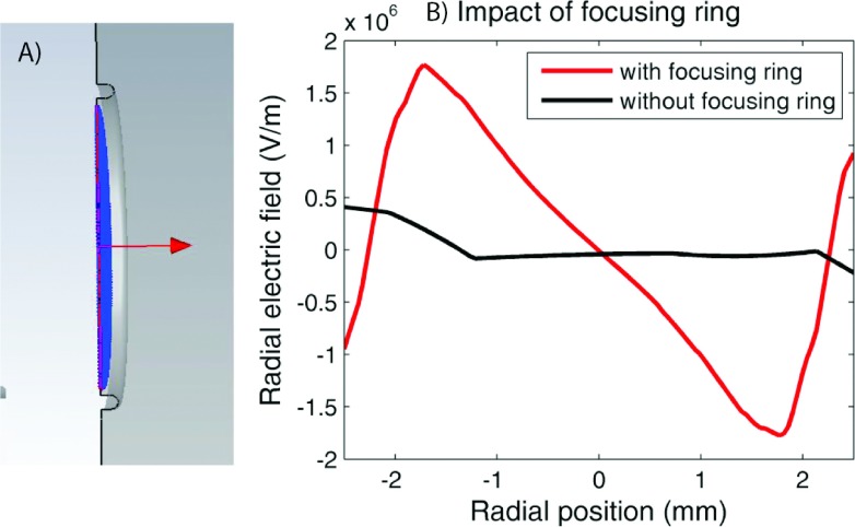
The electromagnetic field solution is shown in Fig. 4 (Multimedia view). Table II shows the frequency, shunt impedance, and quality factor for a single uncoupled accelerating cavity and for the final coupled structure. For comparison, previously published values for the same accelerating cavity are also included. Although further optimization of the RF structure could be undertaken, we did not do this as our goal was to provide a proof of principle, and this was achieved with minimal modifications to the original geometry. As such, there are only two changes to the initial geometry published by St. Aubin. First, in the last cavity, the nose cone length was increased by 0.08 mm to compensate for the fact that there is only one coupling slot present. Second, we added a focusing ring around the cathode to increase the radial focusing fields at the point of emission (Fig. 5). This ring can be described as a half torus with major radius of 2.1 mm and inner radius of 0.2 mm. Further optimization of this structure would be needed for a physical system, but this simple implementation was sufficient for the present work. Although the addition of the focusing ring did slightly affect the RF solution, the frequency, shunt impedance, and quality factor all changed by less than 1%, so no further corrections were made for this.
TABLE II.
Various figures of merit extracted from the simulations. “Single cell” refers to a single uncoupled accelerating cell, whilst the final structure is that shown in Fig. 4. For comparison purpose, the values published by St. Aubin are also included. Note that the uncertainties here refer only to the numerical noise introduced by the mesh size—no other uncertainties are included.
| Metric | Single cell values | Single cell values published in Ref. 18 | Complete waveguide |
|---|---|---|---|
| Frequency (MHz) | 3007.5 ± 0.5 | 3007.23 ± 0.01 | 2998.5 ± 0.5 |
| Quality factor Q0 | 17 509 | 17 521.3 | 16 542 |
| Shunt impedance (MΩ/m) | 165.5 | 165.24 | 109.5 (effective) |
| Transit time factor | 0.8371 | 0.8381 | N/A |
FIG. 5.
(A) shows a cutaway view of the focusing ring around the cathode. (B) shows the impact of this structure of the radial fields, plotted 1 mm in front of the cathode. Note that the asymmetry evident in the plot without the focusing ring is due to the presence of the coupling cavity (see color online version).
In general, the field amplitudes obtained from an eigenmode solver are normalized in a manner specific to a given solver implementation, and must then be scaled to levels appropriate for the need at hand (Fig. 5). However, in the present instance, the original amplitudes were adequate and no further scaling of the fields was required.
3.C. Particle trajectories and beam assessment
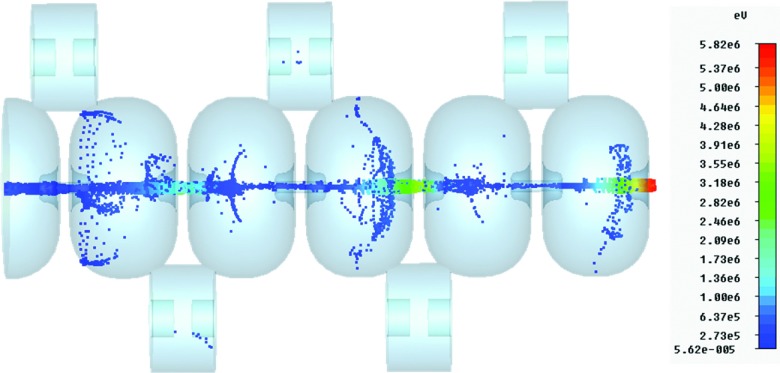
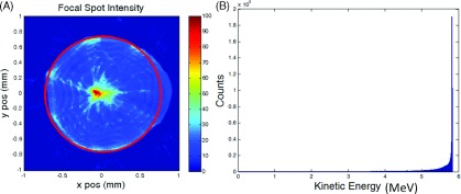
Figure 6 shows a representative snapshot of the particle trajectories (Multimedia view). The particles were scored at the accelerator exit for assessment. The following values were calculated: mean target current 146.3 mA, median energy 5.8 MeV, energy spread (Interquartile range, IQR) 0.1 MeV, spot size (full width at tenth maximum, FWTM) 1.5 mm, and normalized emittance 6.5 mm mrad. The geometric emittance is 0.6 mm mrad. The energy and spatial distributions of the beam are shown in Fig. 7. The spot size is quantified by fitting a circle to the tenth percent intensity iso-line (effectively FWTM). Although we have not explicitly modeled the bremsstrahlung phase space resulting from this electron beam, the spatial and energy parameters listed above are comparable with published values.24,25 Also, relatively little sensitivity in radiation dose distributions has been shown to the target electron beam parameters—the most important factors are mean energy and current.25 As such, we can conclude that a RF source based accelerator is capable of producing an electron beam suitable for radiotherapy.
FIG. 6.
FIG. 7.
(A) Spatial distribution at the target. FWTM is 1.5 mm (circled). (B) Energy histogram at the target. Median energy is 5.8 MeV, interquartile range is 0.1 MeV.
3.D. Back-bombardment power
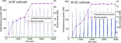
Figure 8 shows the instantaneous power (defined as the energy delivered every 10 ps) and the bunch power, defined as the energy delivered in a bunch multiplied by the frequency of the RF fields (2998.5 MHz). It can be seen that the bunch power rises steadily before plateauing; this behavior occurs because the mean energy of the back-bombarded electrons increases as the forward directed beam propagates further down the accelerator. The steady state back-bombardment power is 23.2 kW for the RF system, and 14.3 kW for the DC system. The mean electron energies are 0.16 and 0.13 MeV, respectively. These numbers take into account all back accelerated electrons. If electrons with a radial coordinate greater than 2 mm (the cathode radius used in this work) are filtered out then the RF back-bombardment power decreases to 19.6 kW, whilst the DC back-bombardment power remains unchanged. It is important to note that none of the models tested here were actually designed to mitigate back-bombardment. It is highly likely that the simulated back-bombardment power could be greatly reduced for both systems modeled here—this is discussed in more detail in Sec. 4. The stated results are during the ∼5 μs beam pulse—the overall mean will be around three orders of magnitude lower than this given medical systems are typically operated with a duty cycle of 0.1%.2
FIG. 8.
Back-bombardment power for (A) the RF system proposed in this work, and (B) a DC based system which has previously been published. The bunch power indicates the mean power delivered per bunch, and steadily rises before reaching a steady state. The bunch segmentation is indicated by the dots along the horizontal axis.
3.E. Performance in magnetic fields
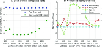
The last step of the study was to compare the zero magnetic field behavior of the novel accelerator with its performance in magnetic fields. Figure 9(A) shows the target current as a function of SID within the fringe field of the 1 T superconducting magnet—for comparison purposes, the current of the conventional diode gun is also plotted. Note that since the accelerator itself is not strongly affected by in-line fields, the losses in target current are proportional to the losses in the electron gun plotted here.
FIG. 9.
(A) Comparison of the current loss versus distance from magnet isocenter for proposed system and a conventional DC electron gun. (B) Various beam metrics at the target versus isocenter position. All metrics are normalized to the zero field values from Sec. 3.C.
It can be seen that the target current of the proposed system is far more robust to operation in in-line magnetic fields, experiencing a maximum of 3% current loss versus 85% for the conventional system. Again, it can be seen that these fields do not affect the behavior of the accelerator. As such, we conclude that a RF-gun based accelerator is capable of robust performance without magnetic shielding in a wide range of in-line magnetic fields.
In Fig. 9(B), the median energy, energy interquartile range, spot size (FWTM), and current are plotted. Each metric is normalized to the zero field values from Sec. 3.C; respectively, 5.8 MeV, 0.1 MeV, 1.5 mm, 143.6 mA. It can be seen that whilst the median energy and current are barely changed by the addition of in-line fields, the spot size and interquartile range undergo large deviations compared to the zero field values. The maximum value of the interquartile range is 0.16 MeV, which is still a very small energy spread. However, the spot size ranges from 0.32 to 2.2 mm—this is discussed further in Sec. 4.
4. DISCUSSION
In this work we have proposed a novel medical electron accelerator with robust target current in a wide range of axial magnetic fields. Further, it does not require ferromagnetic shielding and so does not interfere with the MRI scanner. There are currently three MRI-Linac systems under development. Two utilize the in-line configuration tested in this work, while the third utilizes the perpendicular configuration. Whilst the proposed accelerator design is likely to be slightly more robust to operation in perpendicular fields due to the stiffer beam, this has not been tested in this work. The potential improvement will not be anywhere near as stark as for the in-line case, and a combination of careful placement in low field and magnetic shielding would still be required for optimal performance.
One interesting result is the large variations which occur in spot size as a result of in-line magnetic fields. This is a result of well understood magnetic lensing effects and is explained by Busch’s theorem.26 These effects will occur regardless of the electron source used and have not previously been reported in other work looking at in-line systems. Although this will impact penumbral width, it is expected to have minimal impact on clinical dose distributions, as a number of studies have found that the radiation dose is quite insensitive to the spot size.21,25,27 A more significant effect however may be the local heat load on the tungsten target. Both these effects need be explored in more detail in future work.
We have assumed perfect alignment of the accelerator with the magnetic field in this work. In reality, perfect alignment is not possible. Misalignment between the accelerator and magnetic field increases the radial fields the electrons are subject to, which will cause the electron beam to bend. For small offsets, this will result in a shift in the focal spot, whilst for large enough offsets, partial or full beam loss could result. However, such effects were previously investigated by St. Aubin and found to be small even for exaggerated misalignments.7 Although the fields tested here are much stronger than those previously investigated, preliminary investigations suggest that the impact of misalignments remains small as long as the alignment is within about 2 mm and the SID is greater than 1 m. For SIDs less than 1 m, the magnetic field becomes much stronger, and substantial beam loss could occur. In this scenario, more precise alignment would be required.
There are a number of potential downsides to the use of RF-gun based electron sources for medical accelerator systems which have not been simulated here, and indeed would be difficult to simulate within the present framework. One of these is beam stability. Operating an electron source in the space charge limited regime provides inherent stability, as the resultant current is dependent only on voltage—something which can be controlled with high accuracy and precision. However, in the temperature limited regime, the current is dependent on the cathode temperature and the work function, both of which are more difficult to control. The temperature can fluctuate due to the large temperature gradients present and due to the energy deposited by back accelerated electrons. In existing systems, this is compensated for by active feedback, resulting in pulse to pulse variations of less than 1%.22 As such, we believe that with the present ability to accurately monitor integrated dose, this could also be overcome.
A second issue which would need to be quantified for the proposed system is that of beam on/off latency. Most conventional medical Linacs “gate” the beam using a triode electron gun. In the case of systems which do not use triode guns, rather long beam on/off latencies have been observed.28 The current system would likely exhibit similar latency—however, it is worth noting that the same criticism can be made of currently proposed MRI-Linac systems, which appear to be using diode rather than triode guns at this stage. There have also been triode based RF guns proposed—such a structure may be able to improve the system latency to that achievable with DC triode guns.29
Perhaps the most substantial barrier to clinical implementation of a system such as that described here is the increased back-bombardment power deposited by back accelerated electrons. The results presented in this work suggest that the back-bombardment power is only around 1.5 times higher for the RF cathode than the DC system. However, these results are probably not representative of what would be obtained in real systems for several reasons. First, the field magnitude in the first half cell is typically reduced compared to the field in the rest of the accelerator. This was not done in this work, and would reduce the amount of back-bombarded power. In the case of the DC system, the anode drift tube geometry could also be optimized such that back-bombardment was substantially reduced. As such, the results presented in Sec. 3.D must be considered preliminary. We were not able to find any published literature on the typical extent of back-bombarded power in medical DC electron guns or any information on how much back-bombardment would be acceptable or unacceptable. However, from speaking to industry representatives this appears to be an area to which each accelerator manufacturer has devoted substantial in-house effort. A naïve interpretation of the data presented in Sec. 3.D coupled to CSDA electron ranges30 and data on tungsten cathodes presented in Ref. 17 would lead one to conclude that the temperature of the cathode proposed in this system might rise by over 100° during the beam pulse. However, this ignores that both radiative and conductive heat dissipation are occurring. Based on the published data, we could find (which concerns synchrotron injector guns) a better (but still extremely rough) estimate would be around 50°.17 This would still be a serious issue, resulting in a change in the emitted current by roughly a factor of two, which would also affect the beam loading and hence energy spectrum of the beam at the target. On the other hand, if the dose per pulse remains consistent (i.e., the effect is reproducible), this may not be as large a problem therapeutically as it is for high energy applications where consistent beam quality is extremely important. Further investigation into back-bombardment, its impact on therapeutic beam quality, and mitigation strategies is warranted, but is beyond the scope of this work. A large amount of strategies to mitigate the back-bombardment effect in RF guns has already been published, and given that there is already at least one system in existence operating at similar pulse lengths and energies as would be required for this system (the Kyoto University free electron laser injector), it is reasonable to believe that this effect could be managed.17,29,31
A potential limitation of this work is that no power input port was incorporated into the simulation. It has been previously shown that the presence of a coupling port does introduce further asymmetry into the beam.18 It will also lower the loaded quality factor and shunt impedance of the final structure. However, this work is intended as a proof of principle, and the explicit modeling of an input power port is not anticipated to significantly affect the results. The required input power is dependent on the power losses within the accelerator. As the sources of loss (losses to the conducting walls and to the beam) are very similar to previously published work, the required input power will also be similar to this—around 2.3 MW.18 In a real system, further asymmetry would be introduced into the final electron beam distribution, however, this is the case regardless of the electron source, and is not a significant problem for therapeutic beams in any case.24,25 Previous publications have used a technique whereby the first and last bunch (or half bunch) were removed from the analysis pipeline in order to remove “end effects” from the simulation. We observed minimal bunch to bunch variation in this study (less than 3%) and as such, all macro particles reaching the target were included in the analysis.
We have made minimal effort to optimize the RF structure for a temperature-limited cathode—for instance, further optimization of the radial focusing fields around the cathode could be undertaken, and the spatial energy distribution at the target could be optimized by lowering the fields in the first half cavity.18 The focusing ring used in this study would not be suitable for a physical system, as both Joule heating from the RF fields and thermal isolation from the hot cathode must be considered. However, both issues have been solved in many other RF guns previously and as such are not anticipated to present major challenges.12,22 Again, the purpose of this study was to provide a proof of principle and whilst the above are all interesting directions for future research, they do not counter the proof of principle that has been provided.
5. CONCLUSION
We have investigated the use of a RF electron source based linear accelerator for delivering MRI-Linac radiation therapy. Through the computational simulations, we have shown that such a system is capable of generating an electron beam suitable for therapeutic applications. We have also shown that such a system is far more robust than conventional systems to the presence of in-line magnetic fields, and as such could be an ideal solution for next generation in-line MRI-Linac systems.
ACKNOWLEDGMENTS
Brendan Whelan would like to acknowledge the Centre for Oncology Education and Research Translation (CONCERT) and Cancer Institute NSW for scholarship support. The authors would like to acknowledge the work of Dragos Constantin in developing the DC electron gun model used in this work, and Stefan Kolling and Brad Oborn in developing the magnet model. This study received funding support from the NHMRC (program grant APP1036075) and the NIH (R21 EB015957-02).
REFERENCES
- 1.Ménard C. and van der Heide U., “Introduction: Systems for magnetic resonance image guided radiation therapy,” Semin. Radiat. Oncol. 24, 192 (2014). 10.1016/j.semradonc.2014.02.010 [DOI] [PubMed] [Google Scholar]
- 2.Karzmark C., Nunan C. S., and Tanabe E., Medical Electron Accelerators (McGraw-Hill, Incorporated, Health Professions Division, New York, 1993). [Google Scholar]
- 3.Constantin D. E., Fahrig R., and Keall P. J., “A study of the effect of in-line and perpendicular magnetic fields on beam characteristics of electron guns in medical linear accelerators,” Med. Phys. 38(7), 4174–4185 (2011). 10.1118/1.3600695 [DOI] [PMC free article] [PubMed] [Google Scholar]
- 4.St. Aubin J., Steciw S., and Fallone B., “Effect of transverse magnetic fields on a simulated in-line 6 MV linac,” Phys. Med. Biol. 55(16), 4861–4869 (2010). 10.1088/0031-9155/55/16/015 [DOI] [PubMed] [Google Scholar]
- 5.Keall P. J., Barton M., and Crozier S., “The Australian magnetic resonance imaging–linac program,” Semin. Radiat. Oncol. 24, 203–206 (2014). 10.1016/j.semradonc.2014.02.015 [DOI] [PubMed] [Google Scholar]
- 6.Overweg J. et al. , “System for MRI guided radiotherapy,” in Proceedings of International Society on Magnetic Resonance in Medicine (ISMRM, Concord, CA, 2009), p. 593. [Google Scholar]
- 7.St. Aubin J. et al. , “Effect of longitudinal magnetic fields on a simulated in-line 6 MV linac,” Med. Phys. 37(9), 4916–4923 (2010). 10.1118/1.3481513 [DOI] [PubMed] [Google Scholar]
- 8.Constantin D. E. et al. , “A novel electron gun for inline MRI-linac configurations,” Med. Phys. 41(2), 022301 (10pp.) (2014). 10.1118/1.4860660 [DOI] [PMC free article] [PubMed] [Google Scholar]
- 9.Santos D. et al. , “Magnetic shielding investigation for a 6 MV in-line linac within the parallel configuration of a linac-MR system,” Med. Phys. 39(2), 788–797 (2012). 10.1118/1.3676692 [DOI] [PubMed] [Google Scholar]
- 10.Kolling S., Oborn B., and Keall P., “Impact of the MLC on the MRI field distortion of a prototype MRI-linac,” Med. Phys. 40(12), 121705 (10pp.) (2013). 10.1118/1.4828792 [DOI] [PubMed] [Google Scholar]
- 11.Yun J. et al. , “Brushed permanent magnet DC MLC motor operation in an external magnetic field,” Med. Phys. 37(5), 2131–2134 (2010). 10.1118/1.3392165 [DOI] [PubMed] [Google Scholar]
- 12.Rimjaem S., Kusoljariyakul K., and Thongbai C., “RF study and 3-D simulations of a side-coupling thermionic RF-gun,” Nucl. Instrum. Methods Phys. Res., Sect. A 736, 10–21 (2014). 10.1016/j.nima.2013.10.057 [DOI] [Google Scholar]
- 13.Cronin J., “Modern dispenser cathodes,” in IEE Proceedings I Solid-State and Electron Devices (IEEE, New York, 1981), Vol. 128, pp. 19–32. [Google Scholar]
- 14.Seely S., “Work function and temperature,” Phys. Rev. 59(1), 75–78 (1941). 10.1103/PhysRev.59.75 [DOI] [Google Scholar]
- 15.Semicon Associates, available from http://www.semiconassociates.com/products/microwave.aspx.
- 16.Reiser M., Theory and Design of Charged Particle Beams (John Wiley & Sons, Hokoben, New Jersey, 2008). [Google Scholar]
- 17.Bakr M. et al. , “Back bombardment for dispenser and lanthanum hexaboride cathodes,” Phys. Rev. Spec. Top.–Accel. Beams 14(6), 060708 (2011). 10.1103/PhysRevSTAB.14.060708 [DOI] [Google Scholar]
- 18.St. Aubin J., Steciw S., and Fallone B., “The design of a simulated in-line side-coupled 6 MV linear accelerator waveguide,” Med. Phys. 37(2), 466–476 (2010). 10.1118/1.3276778 [DOI] [PubMed] [Google Scholar]
- 19.Weiland T., “High precision eigenmode computation,” Part. Accel. 56, 61–82 (1996). [Google Scholar]
- 20.Baillie D. et al. , “FEM design and simulation of a short, 10 MV, S-band linac with Monte Carlo dose simulations,” Med. Phys. 42(4), 2044–2053 (2015). 10.1118/1.4915953 [DOI] [PubMed] [Google Scholar]
- 21.St. Aubin J. et al. , “An integrated 6 MV linear accelerator model from electron gun to dose in a water tank,” Med. Phys. 37(5), 2279–2288 (2010). 10.1118/1.3397455 [DOI] [PubMed] [Google Scholar]
- 22.Borland M., A High-Brightness Thermionic Microwave Electron Gun (Department of Applied Physics, Stanford University, Stanford, CA, 1991). [Google Scholar]
- 23.Kowalczyk J. M., Hadmack M. R., and Madey J. M., “Measurement of back-bombardment temperature rise in microwave thermionic electron guns,” Rev. Sci. Instrum. 84(8), 084905 (2013). 10.1063/1.4817539 [DOI] [PubMed] [Google Scholar]
- 24.Jaffray D. et al. , “X-ray sources of medical linear accelerators: Focal and extra-focal radiation,” Med. Phys. 20(5), 1417–1427 (1993). 10.1118/1.597106 [DOI] [PubMed] [Google Scholar]
- 25.Chibani O., Moftah B., and Ma C.-M. C., “On Monte Carlo modeling of megavoltage photon beams: A revisited study on the sensitivity of beam parameters,” Med. Phys. 38(1), 188–201 (2011). 10.1118/1.3523625 [DOI] [PubMed] [Google Scholar]
- 26.Kumar V., “Understanding the focusing of charged particle beams in a solenoid magnetic field,” Am. J. Phys. 77(8), 737–741 (2009). 10.1119/1.3129242 [DOI] [Google Scholar]
- 27.Sheikh-Bagheri D. and Rogers D., “Sensitivity of megavoltage photon beam Monte Carlo simulations to electron beam and other parameters,” Med. Phys. 29(3), 379–390 (2002). 10.1118/1.1446109 [DOI] [PubMed] [Google Scholar]
- 28.Freislederer P. et al. , “Characteristics of gated treatment using an optical surface imaging and gating system on an Elekta linac,” Radiat. Oncol. 10(1), 68–73 (2015). 10.1186/s13014-015-0376-x [DOI] [PMC free article] [PubMed] [Google Scholar]
- 29.Masuda K. et al. , “Particle simulations of a thermionic RF gun with gridded triode structure for reduction of back-bombardment,” Proceedings of the 27th International Free Electron Laser Conference, 2005. [Google Scholar]
- 30.Berger M., estar, pstar, and astar: Computer programs for calculating stopping-power and range tables for electrons, protons, and helium ions, 1992, p. 1.
- 31.Kii T. et al. , “Improvement of electron beam properties by reducing back-bombardment effects in a thermionic RF gun,” Nucl. Instrum. Methods Phys. Res., Sect. A 507(1), 340–344 (2003). 10.1016/S0168-9002(03)00942-2 [DOI] [Google Scholar]


