Abstract
The nematode worm Caenorhabditis elegans has been widely used as a model organism in biological studies because of its short and prolific life cycle, relatively simple body structure, significant genetic overlap with human, and facile/inexpensive cultivation. Microinjection, as an established and versatile tool for delivering liquid substances into cellular/organismal objects, plays an important role in C. elegans research. However, the conventional manual procedure of C. elegans microinjection is labor-intensive and time-consuming and thus hinders large-scale C. elegans studies involving microinjection of a large number of C. elegans on a daily basis. In this paper, we report a novel microfluidic device that enables, for the first time, fully automated, high-speed microinjection of C. elegans. The device is automatically regulated by on-chip pneumatic valves and allows rapid loading, immobilization, injection, and downstream sorting of single C. elegans. For demonstration, we performed microinjection experiments on 200 C. elegans worms and demonstrated an average injection speed of 6.6 worm/min (average worm handling time: 9.45 s/worm) and a success rate of 77.5% (post-sorting success rate: 100%), both much higher than the performance of manual operation (speed: 1 worm/4 min and success rate: 30%). We conducted typical viability tests on the injected C. elegans and confirmed that the automated injection system does not impose significant adverse effect on the physiological condition of the injected C. elegans. We believe that the developed microfluidic device holds great potential to become a useful tool for facilitating high-throughput, large-scale worm biology research.
I. INTRODUCTION
The nematode worm Caenorhabditis elegans (or simply “the worm”) has long been a pivotal model organism in many fields of life sciences including development, aging, neuroscience, and drug screening, among others.1–10 Despite its simple body structure, the genes of C. elegans reveal a substantial overlap (60%–80%) with human genes, and the counterparts of many genes and cellular processes relevant to human diseases are also conserved in this little round worm.11–13 Together with the other advantages of C. elegans, such as ease and low cost of cultivation, rapid and prolific reproduction, short life cycle, and transparent body, C. elegans is the first animal with its genome completely sequenced and mapped, providing a resourceful gene information library.14–16 These properties make C. elegans as an emerging tool for whole-animal drug testing and screening, and its complete genomic resources simplify the further drug target identification.17–19
In worm-based drug testing experiments, C. elegans is exposed to drug solutions via perfusion, feeding, or microinjection, among which microinjection is the only method capable of delivering controlled amounts of drugs to specific intra-body sites. Microinjection is particularly useful for testing water-insoluble drugs for which the perfusion or feeding method is not feasible; it consumes less amount of drugs than other methods, which could be a favorable feature for early-stage drug development where drug candidates are precious.20–26 Besides drug testing/screening applications, microinjection has also been widely used to deliver generic materials (e.g., DNA, morpholino, and RNAi) into the gonad of C. elegans to create transgenetic animals.27
The state-of-the-art manual injection of C. elegans is labor-intensive and inconsistent, leading to low-throughput and uncertainties in results.27,28 To inject a C. elegans worm, it must be first immobilized for subsequent body penetration by a micropipette. The conventional manual immobilization on an agarose plate is time-consuming and can easily damage the worm due to longtime, less-controlled manual operations. These limitations of manual injection significantly restrict the use of the microinjection technique in large-scale studies of C. elegans. Thus, the development of new engineering tools for automated worm injection is highly desired.
Recently, microfluidic devices have significantly facilitated C. elegans handling and advanced various kinds of worm biology research.29–41 Several microfluidic devices have been reported for immobilizing worms in enclosed channels;29,37,39,42 however, they do not allow a micropipette to access the worm body for injection. Two microfluidic devices have been developed to facilitate manual C. elegans microinjection. Ghaemi et al.43 used a narrowed microfluidic channel for immobilizing and injecting single C. elegans worms. This device requires a user to precisely control the position of the worm body inside the immobilization channel by adjusting the loading pressure, which is less-controllable and time-consuming. Zhao et al.44 designed a microfluidic device with an open chamber to immobilize single C. elegans on the side-wall of the open chamber via negative pressure suction. The open chamber design provides more space and freedom for a micropipette to inject the worm body. However, both microfluidic devices43,44 lack on-chip pneumatic valves for continuous worm loading and immobilization, and no automated C. elegans injection was demonstrated. In addition, Hwang et al.45 proposed a worm immobilization method based on sol-gel transition of a worm-carrying hydrogel to immobilize worms for imaging and injection. This method has been further integrated to a microinjection platform for automated worm injection.46 However, the sol-gel translation is relatively slow and thus unsuitable for use in high-speed microinjection of C. elegans.
In this paper, we present a pneumatic-valve-regulated microfluidic device for automated loading, immobilization, and microinjection of single C. elegans. The device design allows individual worms to be sequentially loaded into a microchannel, and the worm handling process is automatically controlled by on-chip pneumatic valves. The microfluidic device is integrated with a robotic system, and custom-made control software coordinates operations of the whole system for full automation. As a proof-of-concept experiment, we use the system to inject 200 C. elegans worms and characterize the system performance. The system demonstrates an injection speed of 6.6 worm/min and a pre-sorting success rate of 77.5% (post-sorting success rate: 100%), both much higher than the performance of manual operation (speed: 1 worm/4 min and success rate: ∼30%; data obtained by a proficient technician in a local C. elegans research laboratory using the standard injection protocol27).
II. EXPERIMENTAL METHODS
A. Device design and fabrication
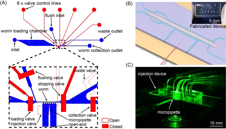
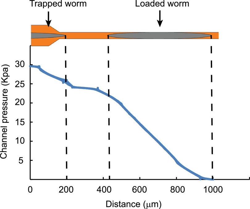
The device, as schematically shown in Fig. 1(a), includes two layers of microchannels: (i) the top fluid-channel layer (blue, 45 μm tall with rectangular cross-sections) for worm immobilization and (ii) the bottom pneumatic-valve layer (red, 30 μm thick) for regulating flows in the top layer. In the top layer, a worm loading chamber with a micro-pillar array inside is used for accommodating C. elegans worms loaded from the device inlet and filtering out debris in the worm-carrying fluid. The spacing of adjacent micro-pillars was designed to be 300 μm, which is small enough to filter out long, wire-like debris but large enough for young adult C. elegans to pass through. An immobilization channel (30 μm wide and 800 μm long) is connected to the worm loading chamber for securely immobilizing a young adult worm (∼40 μm in diameter). Once a worm is loaded into the immobilization channel, the fluid resistance of the immobilization channel is significantly increased and thereby the pressure drop at the inlet of the immobilization channel becomes low (simulation data shown in Fig. 2), keeping the second worm from loading.37,47 An injection channel (420 μm wide) is connected to the side of the immobilization channel and has an open end that allows a micropipette to reach the immobilized worm (Fig. 1(b)). A row of micro-pillars is arranged at the connection of the immobilization and injection channels, which restricts the worm from swimming into the injection channel. A separate flush channel (Fig. 1(a)) is connected to the upstream of the immobilization channel and is responsible for flushing the immobilized worm out of the immobilization channel once the injection is completed. Bifurcated downstream sorting channels collect the successfully injected worms into the collection outlet. Multiple pneumatic micro-valves (Fig. 1(a)) are used to regulate the fluid flows in the immobilization channel, flush channel, and the downstream sorting channels, and are coordinately controlled by custom-made control software. Note that, because of the rectangular cross-sections of the top-layer fluid channel, the micro-valves cannot completely cut off the fluid flows in the channels; however, small leaking flows of the switched-off valves did not affect the operation of the microfluidic device (see operation details in Section II C).
FIG. 1.
Microfluidic device for high-speed microinjection of C. elegans. (a) Schematic layout of the microfluidic device. (b) Blow-up of the injection area on the device. (c) Photograph of an injection device during fluorescence imaging of the injected worm.
FIG. 2.
Finite element simulation result of the pressure profile of the immobilization channel with one worm loaded and another worm at the channel inlet. The simulation was performed in ANSYS 13.0 (Canonsburg, USA). The pressure drop along the worm trapped at the inlet of the immobilization channel is too small to push the animal into the immobilization channel. The 3D model of the immobilization channel and worm and the associated mesh were developed by the ANSYS Workbench 13.0. The worm body was represented by a cylinder with cone-shaped head and tail. Incompressible steady-state Navier-Stokes equations and no-slip boundary conditions were used in the simulation. The pressure difference between the inlet and outlet of the channel was set to be 30 kPa.
The microfluidic device was fabricated via standard multilayer soft lithography.48,49 Briefly, master molds of the flow-channel layer and the control-valve layer were fabricated through photolithography using SU 8-2050 photoresist (45 μm thick) and SU 8-2025 photoresist (30 μm thick), respectively. Both molds were treated with (tridecafluoro-1,1,2,2-tetra-hydrooctyl)-1-trichlorosilane via chemical vapor deposition to prevent the adhesion of molded polydimethylsiloxane (PDMS) to the mold surfaces. PDMS mixture (5:1 ratio) was then poured to the flow-channel mold and degassed for 60 min. Another pre-degassed PDMS mixture (20:1 ratio) was spin coated on the control-valve mold at a speed of 1500 rpm for 30 s to generate a ∼100 μm thick control-valve layer. Both layers were partially cured at 80 °C for 20 min. After punching holes in the flow-channel layer, we manually aligned and bonded the two layers under a stereo microscope and cured the bonded PDMS slab at 80 °C for overnight. To form sealed control-valve channels, the fully cured double-layer PDMS slab was finally bonded with a 25 mm × 75 mm glass slide through oxygen plasma treatment. The surfaces of the PDMS slab and glass slide were treated using a corona surface treater (BD-20AC, Electro-Technic Products, Inc.; power set at the middle level) for 30 s,50 then bonded and heated at 80 °C for 10 min. The fabricated device is shown in Fig. 1(b) (inset).
B. Experimental setup
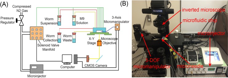
The microfluidic device was integrated with a robotic microinjection system for automated C. elegans microinjection. The system setup, as shown in Fig. 3, is mainly built upon an inverted microscope (10×, Olympus, IX83) with several external components. Compressed nitrogen gas is used to pressurize the on-chip valves, and a custom-made, 16-channel solenoid valve controller is used to automatically regulate the nitrogen gas pressure and thus operate the on-chip valves. The microfluidic device is mounted on a motorized XY stage (ProScan III, Prior), which positions the device under the field of view of the microscope. A glass micropipette, with a tip diameter of 5 μm, is mounted on and automatically controlled by a three-degree-of-freedom (3-DOF) micromanipulator (MP285, Sutter), and a computer-controlled, pressure-driven microinjector (Narishige, IM 300) was connected to the micropipette for precisely regulating the volume of the material injected into the worm body. Real-time visual feedback (25 Hz) is obtained through a complementary metal-oxide semiconductor (CMOS) camera (Basler, A601f) mounted on the microscope, and a host computer is responsible for running the custom-made control software for system automation.
FIG. 3.
System setup for automated C. elegans injection. (a) Schematic layout and (b) photograph of the system.
C. Microfluidic device operation
In order to achieve automated C. elegans injection, the robotic system is developed to (i) coordinate the operations of the on-chip pneumatic valves for loading, immobilization, and downstream sorting of single C. elegans worms; (ii) run real-time image processing algorithms for vertically aligning the injection micropipette tip with the worm body and monitoring the worm loading status inside the immobilization channel; and (iii) automatically control the injection micropipette for injecting the immobilized worm. Here, we focus on the microfluidic device operation, and details of the robotic injection system can be found elsewhere.51
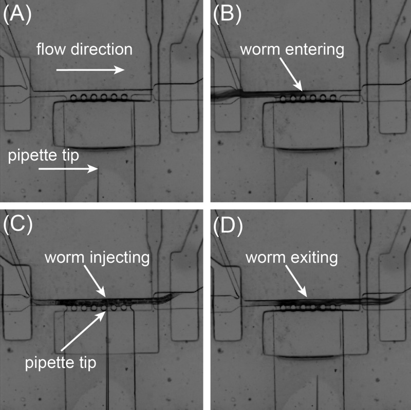
To load the first worm, the entrance and waste valves (Figs. 4(a) and 4(b)) are fully opened, while the exit valve are maintained partially closed to allow fluid passes but keep the worm from swimming through. All other valves are kept closed. Thus, the worm can be directed by a pressure-driven flow into the immobilization channel. Once the robotic system detects the presence of a worm in the immobilization channel via image processing, the entrance valve and the driving pressure applied to the inlet are automatically closed to minimize fluidic fluctuation and allow the worm to be stably immobilized for injection. The injection valve is then opened to allow the micropipette to inject the worm body (Fig. 4(c)). The robotic system allows an operator to choose the injection location on the worm body via computer mouse clicking on a computer screen. During injection, the operator observes the worm body and indicates, through a computer keyboard, to the robotic system whether the current injection is successful. We experimentally proved that a reliable indicator for successful injection is that the worm body slightly expands along its length upon material delivery, and the experimental results will be discussed later in Section III B. After injection, the injection valve is closed and the exit valve is opened. For post-injection worm sorting, based on the operator's feedback on whether the current worm is injected successfully or not, either the worm collection or waste valve is opened. The flush valve is finally switched on and the flush flow (from the flush inlet) is triggered to flush the injected worm out of the immobilization channel (Fig. 4(d)), and the next worm starts to be loaded to the immobilization channel. The valve operation condition for each device state is summarized in Table I. This injection process is repeated until all the worms are loaded to the inlet and injected.
FIG. 4.
Image frame sequence of the injection area of the microfluidic device during worm injection. (a) Before worm loading. (b) A worm entering the immobilization channel. (c) The worm being injected. (d) The worm being flushed away.
TABLE I.
Inlet/valve operation states.
| Inlet/valve states Device states | Loading inlet | Flushing inlet | Loading valve | Flushing valve | Injection valve | Stopping valve | Waste valve | Collection valve |
|---|---|---|---|---|---|---|---|---|
| Worm loading | On | Off | On | Off | Off | Partial off | On | Off |
| Worm immobilization/injection | Off | Off | Off | Off | On | Fully off | On | Off |
| Worm collection | Off | On | Off | On | Off | Fully open | On/off | Off/on |
D. Worm preparation
The wild-type N2 strain of C. elegans was cultured at 20 °C based on an established method.5 C. elegans worms at the young adult stage are usually used in injection experiments, and we thus synchronized the young adult worms using the following protocol. Briefly, 30 gravid adult worms were first transferred to a clean nematode growth media (NGM) agar plate seeded with OP50 strain of E. coli using a worm pick (made from a Pasteur pipette and a titanium wire). The worms were left in the plate for 2 h to collect a large population of worm eggs. The adult worms were then removed from the plate and the eggs with maximum 2-h difference in developmental stage were cultivated at 20 °C for hatching and further development. After 54–60 h, the worms reaching the young adult stage with similar sizes were selectively picked from the plates and suspended in M9 medium with a density of approximately 3000 worms/ml. The worm selection and transferring process typically took less than 25 min for a batch of 40 worms. Before suspending worms, the M9 medium was mixed with Triton X-100 at a v/v ratio of 0.01% to reduce the adherence of C. elegans to plastic tubing and pipette tips, and the mixture solution was filtered using a 0.4 μm syringe filter to remove debris and thus prevent the clogging of the microfluidic channels.
E. Worm viability tests
For post-injection viability tests, control and experimental (injected) groups were chosen from the same culture plates. The control group was kept in M9 medium for the same duration, while the experimental group was in the microfluidic device for injection experiment. To measure the pharyngeal pumping rate, we randomly choose a subset of 15 worms from each group and their pharyngeal pumping rates were measured 2 h after the injection experiment. For long-term developmental tests (i.e., progeny and lifespan tests), another randomly selected subset of 10 worms from each group were placed on separate NGM plates, and the worm progeny numbers were counted 24 h after the injection experiment. All the worms from the control and experimental groups (n = 10 per group) were transferred to newly seeded plates every day in the first 3–5 days post injection experiment in order to separate them from their progeny and their survival rate/lifespan were recorded. A worm was considered dead if it did not respond to a touch applied by a platinum wire.
F. Statistical analysis
All statistical analyses were performed using SPSS 21.0 software (IBM Corporation, Somers, NY). Unpaired, two-tail Student's t-test was used for comparison between the experimental and control groups. One-way ANOVA test was used for comparison of the average injection speed (or average injection time per worm) achieved using different microfluidic devices. A comparison with p < 0.05 was considered statistically significant.
III. RESULTS AND DISCUSSION
A. Optimization of experimental parameters
To achieve stable operation of the microfluidic device, we optimized several important operation parameters through trial-and-error experiments. To guarantee reliable worm loading, we carefully examined the developmental stage of the worms to be injected and ensured all the young adult worms to have similar diameters (35–40 μm). If smaller worms exist in an injection batch, the occurrence of simultaneous loading of two worms (double-loading problem) increases significantly, thus lowering the injection success rate. If a worm is much larger (>60 μm in diameter) than the immobilization channel width, the device requires much longer time to direct the worm into the channel and thereby lowering the injection speed, and the channel may be permanently blocked by the large worm (blocking problem). With careful visual selection of worms with the right sizes, we avoided the blocking problem and minimized the occurrence of the double-loading problem. We also investigated the effect of the micropipette tip size and experimentally determined an effective tip outer diameter of 5 μm (inner diameter: 3.5 μm). We found that micropipettes with tips smaller than 5 μm (e.g., 2–3 μm) were prone to be bent during worm body penetration and that micropipettes with much larger tips than 5 μm (e.g., 8–10 μm) did not penetrate the worm body efficiently. We also experimentally determined an effective penetration/retraction speed of 5000 μm/s of the micropipette, which yielded the minimal worm body lysis and the highest post-injection survival rate.
B. Characterization of worm injection performance
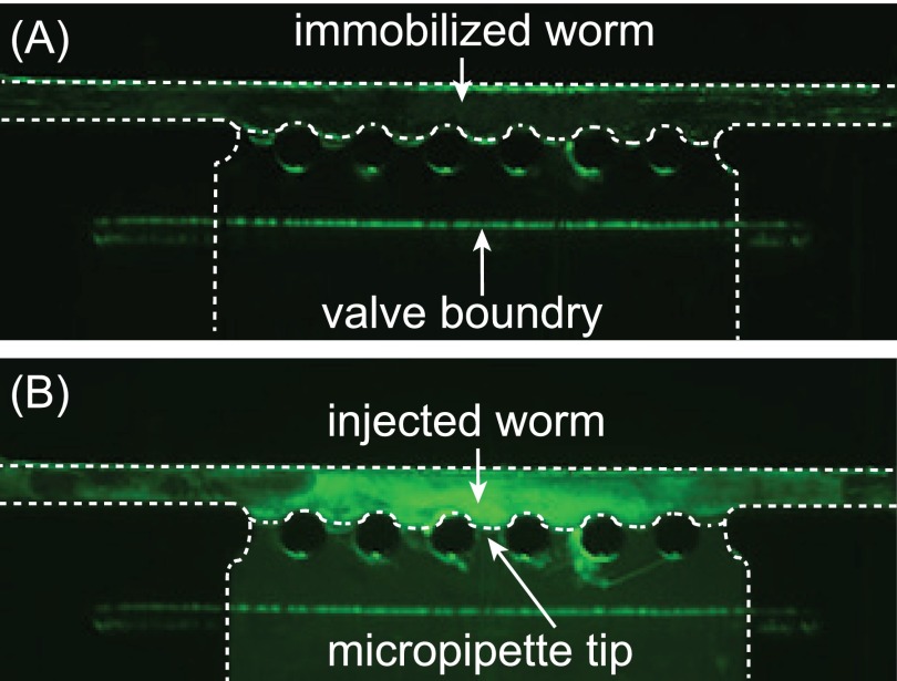
Before the injection experiment, we first confirmed that the worm body expansion is a reliable indicator for successful injection. We injected 85 pl of fluorescein isothiocyanate (FITC) dye into a worm and then immediately observed its body using a fluorescence camera. We found that the worm body expanded along its length upon material delivery. In the meanwhile, the fluorescence imaging showed that the fluorescence intensity of the worm body was much higher in the proximity of injection location (Fig. 5), indicating that the fluorescent dye had been successfully injected into the worm body without flowing out. We repeated this examination for 20 worms and did not found any false positive case (that is, a worm expanded upon material delivery but no fluorescent dye was observed in the worm body). These results demonstrate that the worm body expansion is a reliable indictor for successful injection and can be used for following injection experiments.
FIG. 5.
Experimental validation of the worm body expansion as a reliable indication for successful injection. The dashed lines show the boundaries of the worm and the PDMS channel. (a) An immobilized worm before injection of fluorescence dye. No obvious fluorescence signal was observed in the worm body. (b) The worm after injection of fluorescence dye. The injected fluorescence dye was observed in the proximity of the injection site, which correlates the worm body expansion observed during injection.
To evaluate the injection efficiency of the microfluidic device, we performed automated injection of 200 worms (from five devices, 40 worms per device) using de-ionized (DI) water (injection volume: 85 pl) and characterized two performance parameters: (i) injection speed (defined as the number of injected worms per unit time) and (ii) success rate (defined as the ratio of the number of the successfully injected worms to the total number of injected worms). The automated process of C. elegans injection is shown in the supplementary Video S1.54 Although we have optimized the injection/retraction speeds of the injection micropipette, there was still a small amount of lysis from the worm body when the micropipette was retracted out of the body (Video S154). This was primarily because the worm body was compressed by the immobilization channel and the intra-body pressure caused the gentle lysis. The lysis also induced a small amount of the injection material flow out form the worm body after injection. We have confirmed, in the post-injection viability tests (data shown in Subsection III C), the injection-induced lysis is less likely to cause any significant adverse effect on the physiological and developmental conditions of the injected C. elegans.
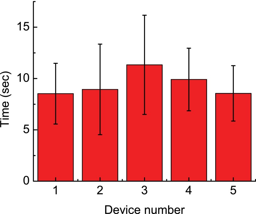
We achieved an average injection speed of 6.6 worm/min (average worm handling time: 9.45 s/worm) and a pre-soring success rate of 77.5%. Both parameters are much higher than the performance of manual operation (speed: 1 worm per 4 min and success rate: ∼30%; personal communication55). Since the microfluidic device sorted the successfully injected worms to the worm collection outlet, the post-sorting success rate of the device was 100%. There were two failure modes occurring during worm injection. One was that no worm body expansion was observed during injection (occurrence rate: 19.5%, n = 200). Possible reasons for these failures include temporary clogging of the micropipette by worm body debris and non-penetration of the worm body by the micropipette (which was because of the slight misalignment of the vertical positions of the micropipette tip and worm body center). The other failure mode was attributed to the worm double loading (occurrence rate: 3%, n = 200). Though the sizes of loaded worms were selected carefully via visual inspection, there was still a small chance for two worms to be loaded into the immobilization channel simultaneously. More accurate size synchronization of the loaded worms could be achieved using computer vision algorithms.38,56 We also quantified the device-to-device variation in the worm handling time (i.e., average time required to injection one worm). The average worm handling time obtained from each device are shown in Fig. 6. We found no statically difference among the average worm handling time of the five devices. These results suggest that the device operation is repeatable in automated C. elegans microinjection.
FIG. 6.
The average worm handling time obtained in worm injection experiments on five different microfluidic devices, showing repeatable injection speed of the system using different devices.
The high-speed characteristic of our worm injection system is mainly contributed by the automated, high-speed worm loading, immobilization, and post-injection sorting realized on the microfluidic device. Further increase of the injection speed can be possibly achieved by developing an image processing algorithm for automatically detecting the worm body expansion upon injection and thus eliminating the requirement of user input (which is relatively slow). The success rate could be further enhanced through (i) addressing the issues of micropipette clogging and pipette-worm body misalignment and (ii) more accurate on-chip size synchronization method of the loaded worms using a microfluidic device integrated with computer vision algorithms for automatic worm sizing.33,38,56
The current worm injection system is more suitable for drug testing/screening applications (in which drug/chemical solutions need to be injected into the worm body);20,25 however, it is still challenging for the system to perform microinjection of the worm gonad for creating transgenic C. elegans due to the following reasons. The microfluidic device uses a narrow channel to immobilize a C. elegans worm, and the compressed worm body makes the visual identification of the gonad difficult. In addition, the device does not have any control of the worm body orientation along the dorso-ventral axis; thus, it is likely the worm gonad will not face the injection micropipette after immobilized, which makes the gonad injection more challenging. To achieve gonad injection of C. elegans, the worm immobilization mechanism on the microfluidic device can be revised by incorporating a method for orientation control of the worm body along the dorso-ventral axis.52
C. Post-injection viability test
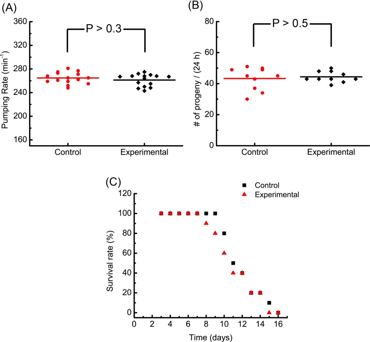
To investigate the possible biological effect of the robotic injection on the C. elegans, we first measured the pharynx pumping rate of the injected C. elegans, which is a widely used quantitative indicator for the worm's physiological condition. As shown in Fig. 7(a), there is no significant difference in the pharynx-pumping rate measured from the experimental and control groups (n = 15). The pumping rate ranges in 240–280 pumps/min for both groups and is in good agreement with values reported in the previous studies on the wild-type N2 worms.33 This indicates that the microfluidic device and the automated robotic injection are less likely to induce adverse effects on the physiological condition of the injected C. elegans.
FIG. 7.
Experimental results of post-injection viability tests. (a) Pharyngeal pumping rates of the control and experimental (injected) groups (n = 15). (b) Number of eggs laid per worm at 24 h post injection from the control and experimental groups (n = 10). (c) The daily survival rates of the control and experimental groups (n = 10). Worms hatched from eggs on day 0 and were loaded into the microfluidic device for injection experiments on day 3.
We also examined the development of the injected C. elegans by quantifying two parameters: (i) the fecundity 24 h post injection and (ii) the survival rate within the entire lifespan. As shown in Fig. 7(b), an average of ∼42 progenies were observed at 24 h post injection for both the experimental and control groups (n = 10) and no statistical difference was found in the fecundity of the two groups. For studying the lifespan of the injected C. elegans, the daily survival rates of the experimental and control groups (n = 10) worms are shown in Fig. 7(c). No statistical difference in the daily survival rate was observed when comparing the two groups. In both groups, all the worms survived at least 8 days, which is consistent with the previously reported lifespan of wide-type N2 worms.53 Therefore, we conclude that there is no evidence showing that the worm development was adversely affected by the automated robotic injection.
IV. CONCLUSIONS
In this paper, we reported a microfluidic device capable of rapid loading, immobilization, injection, and sorting of C. elegans with an injection speed of 6.6 worm/min and a pre-sorting success rate of 77.5%. Different from existing microfluidic devices for C. elegans injection, this device requires minimal human intervention, is operated automatically, and provides significantly improved injection speed and success rate over conventional manual operation. The automated injection system we developed also allows for real-time, online monitoring of the injection experiment by a user and gives much freedom to the user to decide the injection location, which makes the device operation more straightforward and efficient. We believe that this device holds great potential to change the way how C. elegans is injected and thus significantly facilitate worm biology studies which routinely involve high-volume worm injection experiments.
ACKNOWLEDGMENTS
This work was supported by Natural Sciences and Engineering Research Council of Canada (NSERC, Grant No. RGPIN 418553-12), Canada Foundation for Innovation (CFI, Grant No. CFI-LOF 30316), Le Fonds de recherche du Quebec - Nature et technologies (FRQNT, Grant No. 2013-NC-166238), and McGill University (Grant No. 234304). The authors also acknowledge supports from the Canada Research Chairs Program (to X. Liu, Grant No. 237293) and the China Scholarship Council (to P. Song and X. Dong). The authors also acknowledge the assistance from the laboratory of Prof. Michael Hendricks at McGill University on worm culture.
References
- 1. Bargmann C. I., Annu. Rev. Neurosci. 16(1), 47–71 (1993). 10.1146/annurev.ne.16.030193.000403 [DOI] [PubMed] [Google Scholar]
- 2. Ellis H. M. and Horvitz H. R., Cell 44(6), 817–829 (1986). 10.1016/0092-8674(86)90004-8 [DOI] [PubMed] [Google Scholar]
- 3. Kenyon C. J., Nature 464(7288), 504–512 (2010). 10.1038/nature08980 [DOI] [PubMed] [Google Scholar]
- 4. Wang X., Yang C., Chai J., Shi Y., and Xue D., Science 298(5598), 1587–1592 (2002). 10.1126/science.1076194 [DOI] [PubMed] [Google Scholar]
- 5. Brenner S., Genetics 77(1), 71–94 (1974). [DOI] [PMC free article] [PubMed] [Google Scholar]
- 6. Ewbank J. J. and Zugasti O., Dis. Model. Mech. 4(3), 300–304 (2011). 10.1242/dmm.006684 [DOI] [PMC free article] [PubMed] [Google Scholar]
- 7. Van Raamsdonk J. M. and Hekimi S., Antioxid. Redox. Signal. 13(12), 1911–1953 (2010). 10.1089/ars.2010.3215 [DOI] [PubMed] [Google Scholar]
- 8. Wen Q., Po M. D., Hulme E., Chen S., Liu X., Kwok S. W., Gershow M., Leifer A. M., Butler V., Fang-Yen C. et al. , Neuron 76(4), 750–761 (2012). 10.1016/j.neuron.2012.08.039 [DOI] [PMC free article] [PubMed] [Google Scholar]
- 9. Zhang Y., Lu H., and Bargmann C. I., Nature 438(7065), 179–184 (2005). 10.1038/nature04216 [DOI] [PubMed] [Google Scholar]
- 10. Hendricks M., Ha H., Maffey N., and Zhang Y., Nature 487(7405), 99–103 (2012) 10.1038/nature11081. [DOI] [PMC free article] [PubMed] [Google Scholar]
- 11. Artal-Sanz M., de Jong L., and Tavernarakis N., Biotechnol. J. 1(12), 1405–1418 (2006). 10.1002/biot.200600176 [DOI] [PubMed] [Google Scholar]
- 12. Nussbaum-Krammer C. I. and Morimoto R. I., Dis. Model. Mech. 7(1), 31–39 (2014). 10.1242/dmm.013011 [DOI] [PMC free article] [PubMed] [Google Scholar]
- 13. Hillier L. W., Coulson A., Murray J. I., Bao Z., Sulston J. E., and Waterston R. H., Genome Res. 15(12), 1651–1660 (2005). 10.1101/gr.3729105 [DOI] [PubMed] [Google Scholar]
- 14. Hulme S. E. and Whitesides G. M., Angew. Chem., Int. Ed. 50(21), 4774–4807 (2011). 10.1002/anie.201005461 [DOI] [PubMed] [Google Scholar]
- 15. Hillier L. W., Marth G. T., Quinlan A. R., Dooling D., Fewell G., Barnett D., Fox P., Glasscock J. I., Hickenbotham M., Huang W. et al. , Nat. Methods. 5(2), 183–188 (2008). 10.1038/nmeth.1179 [DOI] [PubMed] [Google Scholar]
- 16.C. elegans Sequencing Consortium, Science 282(5396), 2012–2018 (1998). 10.1126/science.282.5396.2012 [DOI] [PubMed] [Google Scholar]
- 17. O'Reilly L. P., Luke C. J., Perlmutter D. H., Silverman G. A., and Pak S. C., Adv. Drug Deliv. Rev. 69, 247–253 (2014). 10.1016/j.addr.2013.12.001 [DOI] [PMC free article] [PubMed] [Google Scholar]
- 18. Bargmann C. I. and Horvitz H. R., Neuron 7(5), 729–742 (1991). 10.1016/0896-6273(91)90276-6 [DOI] [PubMed] [Google Scholar]
- 19. Kaletta T. and Hengartner M. O., Nat. Rev. Drug Discov. 5(5), 387–399 (2006). 10.1038/nrd2031 [DOI] [PubMed] [Google Scholar]
- 20. Leung M. C., Williams P. L., Benedetto A., Au C., Helmcke K. J., Aschner M., and Meyer J. N., Toxicol. Sci. 106(1), 5–28 (2008). 10.1093/toxsci/kfn121 [DOI] [PMC free article] [PubMed] [Google Scholar]
- 21. Avery L. and Horvitz H. R., J. Exp. Zool. 253(3), 263–270 (1990). 10.1002/jez.1402530305 [DOI] [PubMed] [Google Scholar]
- 22. Nakanishi N., Nakajima M., Hisamoto N., Takeuchi M., Homma M., and Fukuda T., paper presented at the International Symposium on Micro-NanoMechatronics and Human Science (MHS), 2013. [Google Scholar]
- 23. Nakajima M., Hirano T., Kojima M., Hisamoto N., Nakanishi N., Tajima H., Homma M., and Fukuda T., paper presented at the IEEE/RSJ International Conference on Intelligent Robots and Systems (IROS), 2012. [Google Scholar]
- 24. Nakajima M., Hirano T., Kojima M., Hisamoto N., Homma M., and Fukuda T., paper presented at the IEEE International Conference on Robotics and Automation (ICRA), 2011. [Google Scholar]
- 25. Mohan N., Chen C.-S., Hsieh H.-H., Wu Y.-C., and Chang H.-C., Nano Lett. 10(9), 3692–3699 (2010). 10.1021/nl1021909 [DOI] [PubMed] [Google Scholar]
- 26. Liu J.-H., Yang S.-T., Chen X.-X., and Wang H., Curr. Drug Metab. 13(8), 1046–1056 (2012). 10.2174/138920012802850083 [DOI] [PubMed] [Google Scholar]
- 27.Transformation and Microinjection, edited by Evans T. C. ( WormBook, 2006), pp. 1–15. [Google Scholar]
- 28. Kimble J., Hodgkin J., Smith T., and Smith J., Nature 299, 456–458 (1982). 10.1038/299456a0 [DOI] [PubMed] [Google Scholar]
- 29. Crane M. M., Stirman J. N., Ou C.-Y., Kurshan P. T., Rehg J. M., Shen K., and Lu H., Nat. Methods 9(10), 977 (2012). 10.1038/nmeth.2141 [DOI] [PMC free article] [PubMed] [Google Scholar]
- 30. Chung K., Zhan M., Srinivasan J., Sternberg P. W., Gong E., Schroeder F. C., and Lu H., Lab Chip 11(21), 3689–3697 (2011). 10.1039/c1lc20400a [DOI] [PMC free article] [PubMed] [Google Scholar]
- 31. Shi W., Qin J., Ye N., and Lin B., Lab Chip 8(9), 1432–1435 (2008). 10.1039/b808753a [DOI] [PubMed] [Google Scholar]
- 32. Rohde C. B., Zeng F., Gonzalez-Rubio R., Angel M., and Yanik M. F., Proc. Natl. Acad. Sci. U.S.A. 104(35), 13891–13895 (2007). 10.1073/pnas.0706513104 [DOI] [PMC free article] [PubMed] [Google Scholar]
- 33. Ai X., Zhuo W., Liang Q., McGrath P. T., and Lu H., Lab Chip 14(10), 1746–1752 (2014). 10.1039/C3LC51334C [DOI] [PMC free article] [PubMed] [Google Scholar]
- 34. Chronis N., Lab Chip 10(4), 432–437 (2010). 10.1039/B919983G [DOI] [PubMed] [Google Scholar]
- 35. Lockery S. R., Lawton K. J., Doll J. C., Faumont S., Coulthard S. M., Thiele T. R., Chronis N., McCormick K. E., Goodman M. B., and Pruitt B. L., J. Neurophysiol. 99(6), 3136–3143 (2008). 10.1152/jn.91327.2007 [DOI] [PMC free article] [PubMed] [Google Scholar]
- 36. Bakhtina N. A. and Korvink J. G., RSC Adv. 4(9), 4691–4709 (2014). 10.1039/C3RA43758B [DOI] [Google Scholar]
- 37. Chung K., Crane M. M., and Lu H., Nat. Methods 5(7), 637–643 (2008). 10.1038/nmeth.1227 [DOI] [PubMed] [Google Scholar]
- 38. Song P., Zhang W., Sobolevski A., Bernard K., Hekimi S., and Liu X., Biomed. Microdevices 17(2), 1–10 (2015) 10.1007/s10544-015-9939-8. [DOI] [PubMed] [Google Scholar]
- 39. Hulme S. E., Shevkoplyas S. S., Apfeld J., Fontana W., and Whitesides G. M., Lab Chip 7(11), 1515–1523 (2007). 10.1039/b707861g [DOI] [PubMed] [Google Scholar]
- 40. Ben-Yakar A., Chronis N., and Lu H., Curr. Opin. Neurobiol. 19(5), 561–567 (2009). 10.1016/j.conb.2009.10.010 [DOI] [PMC free article] [PubMed] [Google Scholar]
- 41. Johari S., Nock V., Alkaisi M. M., and Wang W., Lab Chip 13(9), 1699–1707 (2013). 10.1039/c3lc41403e [DOI] [PubMed] [Google Scholar]
- 42. Krajniak J. and Lu H., Lab Chip 10(14), 1862–1868 (2010). 10.1039/c001986k [DOI] [PMC free article] [PubMed] [Google Scholar]
- 43. Ghaemi R., paper presented at the 17th International Conference on Miniaturized Systems for Chemistry and Life Sciences (MicroTAS 2013), Freiburg, Germany, 2013. [Google Scholar]
- 44. Zhao X., Xu F., Tang L., Du W., Feng X., and Liu B.-F., Biosens. Bioelectron. 50, 28–34 (2013). 10.1016/j.bios.2013.06.024 [DOI] [PubMed] [Google Scholar]
- 45. Hwang H., Krajniak J., Matsunaga Y., Benian G. M., and Lu H., Lab Chip 14(18), 3498–3501 (2014). 10.1039/C4LC00697F [DOI] [PMC free article] [PubMed] [Google Scholar]
- 46. Gilleland C. L., Falls A. T., Noraky J., Heiman M. G., and Yanik M. F., Genetics 201, 39–46 (2015) 10.1534/genetics.115.179648. [DOI] [PMC free article] [PubMed] [Google Scholar]
- 47. Shen F., Li X., and Li P. C. H., Biomicrofluidics 8(1), 014109 (2014). 10.1063/1.4866358 [DOI] [PMC free article] [PubMed] [Google Scholar]
- 48. Xia Y. and Whitesides G. M., Annu. Rev. Mater. Sci. 28(1), 153–184 (1998). 10.1146/annurev.matsci.28.1.153 [DOI] [Google Scholar]
- 49. Unger M. A., Chou H.-P., Thorsen T., Scherer A., and Quake S. R., Science 288(5463), 113–116 (2000). 10.1126/science.288.5463.113 [DOI] [PubMed] [Google Scholar]
- 50. Haubert K., Drier T., and Beebe D., Lab Chip 6(12), 1548–1549 (2006). 10.1039/b610567j [DOI] [PubMed] [Google Scholar]
- 51. Dong X., Song P., and Liu X., paper presented at the IEEE International Conference on Robotics and Automation (ICRA), 2015. [Google Scholar]
- 52. de Carlos Cáceres I., Valmas N., Hilliard M. A., and Lu H., PLoS ONE 7(4), e35037 (2012). 10.1371/journal.pone.0035037 [DOI] [PMC free article] [PubMed] [Google Scholar]
- 53. Hulme S. E., Shevkoplyas S. S., McGuigan A. P., Apfeld J., Fontana W., and Whitesides G. M., Lab Chip 10(5), 589–597 (2010). 10.1039/B919265D [DOI] [PMC free article] [PubMed] [Google Scholar]
- 54.See supplementary material at http://dx.doi.org/10.1063/1.4941984E-BIOMGB-10-010698 for real-time C. elegans microinjection video.
- 55. Juan C. (private communication, 2014).
- 56. Song P., Dong X., and Liu X., paper presented at The 19th International Conference on Miniaturized Systems for Chemistry and Life Sciences (MicroTAS 2015), 25–29 October 2015, Gyeongju, Korea. [Google Scholar]
Associated Data
This section collects any data citations, data availability statements, or supplementary materials included in this article.
Data Citations
- See supplementary material at http://dx.doi.org/10.1063/1.4941984E-BIOMGB-10-010698 for real-time C. elegans microinjection video.


