Abstract
This paper presents a continuous glucose monitoring microsystem consisting of a three-electrode electrochemical sensor integrated into a microfluidic chip. The microfluidic chip, which was used to transdermally extract and collect subcutaneous interstitial fluid, was fabricated from five polydimethylsiloxane layers using micromolding techniques. The electrochemical sensor was integrated into the chip for continuous detection of glucose. Specifically, a single-layer graphene and gold nanoparticles (AuNPs) were decorated onto the working electrode (WE) of the sensor to construct a composite nanostructured surface and improve the resolution of the glucose measurements. Graphene was transferred onto the WE surface to improve the electroactive nature of the electrode to enable measurements of low levels of glucose. The AuNPs were directly electrodeposited onto the graphene layer to improve the electron transfer rate from the activity center of the enzyme to the electrode to enhance the sensitivity of the sensor. Glucose oxidase (GOx) was immobilized onto the composite nanostructured surface to specifically detect glucose. The factors required for AuNPs deposition and GOx immobilization were also investigated, and the optimized parameters were obtained. The experimental results displayed that the proposed sensor could precisely measure glucose in the linear range from 0 to 162 mg/dl with a detection limit of 1.44 mg/dl (S/N = 3). The proposed sensor exhibited the potential to detect hypoglycemia which is still a major challenge for continuous glucose monitoring in clinics. Unlike implantable glucose sensors, the wearable device enabled external continuous monitoring of glucose without interference from foreign body reaction and bioelectricity.
I. INTRODUCTION
Continuous blood glucose monitoring is important for the treatment of diabetes. Currently, the implantable enzyme electrode sensors are frequently used for continuous glucose monitoring in clinics.1 However, the invasive measurement and the short lifetime of the electrodes as a result of the foreign body reactions in the subcutaneous tissue restrict its application. Furthermore, it is difficult for the implanted sensors to accurately measure the glucose concentrations due to the signal drift caused by the bioelectricity of the human body.2 On the other hand, modern medical science indicates that the glucose concentrations in the interstitial fluid (ISF) are closely related to those in the blood.3 Thus, blood glucose prediction based on the glucose measurement in transdermally extracted ISF has become an emerging technology for continuous glucose monitoring. This method can realize non-invasive extracorporeal detection, which allows the glucose sensor to avoid the interference with the internal environment.
A microfluidic chip has been fabricated by our research group to non-invasively extract the ISF from the subcutaneous tissue.4 The ISF extraction chip featured five polydimethylsiloxane (PDMS) layers and was fabricated by micromolding techniques. First, ultrasound was used to pretreat the skin of the extraction area. Micropores were generated to increase the permeability of the skin when the ultrasound treatment was successful.5 Then, vacuum pressure was applied to transdermally extract the ISF over an area of 0.07 cm2 using this chip. It was difficult to collect ISF because it was scattered on the surface of the skin and was a volume of approximately 1 μl.6 Therefore, a predefined volume of phosphate buffer was used to dilute the transdermally extracted ISF to simplify collection. However, the glucose concentration of the ISF decreased significantly after dilution. Moreover, it is difficult to fabricate the electrodes of the glucose sensor on the PDMS surface because it is hydrophobic and exhibits poor adhesion to metals.7 Accordingly, in this paper, a high-resolution electrochemical sensor was fabricated on a glass substrate, which can be integrated into the microchannel of the chip to accurately measure the glucose concentrations in the diluted ISF.
The existing commercial glucometers can measure concentrations ranging from 20 to 500 mg/dl; however, these devices are not capable of detecting glucose in the diluted ISF as the concentration can be as low as approximately 2 mg/dl. Researchers are developing novel glucose sensors based on new technologies. The enzyme-based electrochemical flow-through glucose sensor that can be integrated into a flow channel was proposed by Zimmermann et al.;8 the detection limit of the sensor is 20 mg/dl. A capacitive MEMS affinity sensor for continuous glucose monitoring was reported by Huang et al.;9 the sensor could measure glucose at the physiologically relevant concentrations ranging from 30 to 360 mg/dl. Tierney et al.10 proposed a sensor prepared by the incorporation of 3-phenylboronic acid and dimethylaminopropylacrylamide into a hydrogel covalently linked to the end of an optical fiber. This glucose sensor was capable of measuring physiological glucose levels, with a detection limit of 18 mg/dl. The glucose biosensor fabricated by Tashkhourian et al.11 employed a chromophore (silver nanoparticles)-mediated decolorization method for the photometric determination of glucose. The linear range of this glucose sensor was from 50 to 800 mg/dl; and the detection limit was determined to be 23 mg/dl. Genetically engineered polypeptide-based fluorescent binding molecules were introduced by Siegrist et al.12 to improve the accuracy of the glucose sensor for continuous glucose detection. The linear range of the glucose sensor spanned from 35 to 586 mg/dl. Although these sensors had various merits, none of them met the requirement for measuring the low glucose concentration in diluted ISF with high accuracy because their detection range only included the physiological range.
In this paper, we present a continuous glucose monitoring microsystem consisting of a three-electrode electrochemical sensor integrated into the PDMS-based microfluidic chip. The microfluidic chip was used to transdermally extract ISF in a non-invasive way. The electrochemical sensor was integrated into the ISF extraction chip to detect glucose continuously. Specifically, a single-layer graphene and gold nanoparticles (AuNPs) were decorated onto the working electrode (WE) of the sensor to construct a composite nanostructured surface to improve the resolution of the glucose measurements. Graphene was transferred onto the WE surface to improve the electroactive nature of the electrode and enable measurements of low levels of glucose. The AuNPs were directly electrodeposited onto the graphene layer to improve the electron transfer rate from the activity center of the enzyme to the electrode and enhance the sensitivity of the sensor. Finally, glucose oxidase (GOx) was immobilized onto the composite nanostructured surface by electrochemical polymerization to specifically detect glucose. Additionally, the factors required for AuNPs deposition and GOx immobilization were also investigated, and the optimized parameters were obtained. Unlike the implantable glucose sensors, the wearable device enabled external continuous monitoring of glucose without interference from foreign body reactions and bioelectricity.
II. MATERIALS AND METHODS
A. Materials and apparatus
d–(+)-glucose, chloroauric acid (HAuCl4), and sodium sulfite (Na2SO4) were purchased from Shanghai Xinbo Chemistry Technique Co., China. GOx, 3,4-ethylenedioxythiophene (EDOT), and poly (4-styrenesulfonic) (PSS) were purchased from Sigma-Aldrich, Inc., USA. Silver nitrate (AgNO3), ammonia water (NH3·H2O), hydrogen dioxide solution (H2O2, 30 wt. %), ferric chloride (FeCl3), sodium dihydrogen phosphate (NaH2PO4), and disodium hydrogen phosphate (Na2HPO4) were obtained from Tianjin Jiangtian Huagong Co., China. A single-layer graphene was purchased from ACS Material LLC, USA. The 0.1 M phosphate buffer solution (PBS) was prepared freshly from the NaH2PO4 and Na2HPO4 reagents. All aqueous solutions were prepared with deionized water using a Milli-Q filter (Elix™ Essential 5, Merck Millipore, Germany). All chemicals were of analytical grade or better and were used as received without further purification.
The AuNPs were electrodeposited onto the electrode surface by an electrochemical workstation (CHI 660E, CHI Instruments, Inc., USA). And all electrochemical experiments were performed using this workstation. All potentials were reported against the Ag/AgCl reference electrode.
B. Design and fabrication of the ISF extraction microfluidic chip
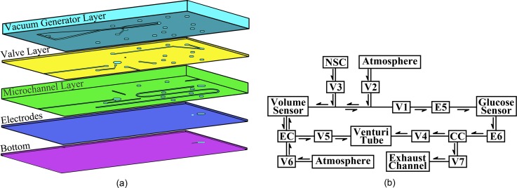
The microfluidic chip was fabricated from five PDMS layers, which included a vacuum generator layer, a valve layer, a microchannel layer, an electrodes layer, and a bottom layer, as shown in Figure 1(a), using micromolding techniques.4 The schematic diagram of the working process for the microfluidic chip is shown in Figure 1(b). This chip consisted of a Venturi tube13 to provide a driving force for both ISF extraction and fluid manipulation, pneumatic valves to sequentially control the ISF extraction and collection processes, fluid chambers for the storage of the extracted and collected ISF, and interconnecting microchannels. In addition, a volume sensor was integrated into this ISF extraction microfluidic chip to monitor the input volumes of the phosphate buffer and associated diluted ISF. The two pairs of electrodes (E5 and E6) were placed at the front and rear sides of the access ports to stop the collected sample between the two electrode pairs for the glucose concentration measurements. The ISF extraction chip is sealed onto the skin surface during the ISF extraction, collection, and measurement processes. First, the Venturi tube and a pump outside the chip provide a stable vacuum to transdermally extract the ISF. Second, a defined volume of normal saline, which is stored in the normal saline chamber, is injected into the extraction chamber to help collect the scattered ISF on the skin surface. Next, the extracted ISF is mixed with normal saline to form a manipulable volume of fluid. Then, the mixed fluid volume is measured as it is transferred from the extraction chamber to the collection chamber, which contains the glucose sensor. Finally, the glucose concentration in the mixture is measured by the proposed electrochemical sensor. As the volumes of the saline and the mixture are known, the glucose concentration in the extracted ISF can be calculated.
FIG. 1.
Schematic of the ISF extraction microfluidic chip: (a) Five-layer structure of the chip. (b) Working process of the chip. V1–V7: pneumatic valves, E5–E6: two pairs of electrodes, EC: extraction chamber, NSC: normal saline chamber, and CC: collection chamber.
C. Design and fabrication of the three-electrode electrochemical sensor
The schematic of the proposed glucose sensor is shown in Figure 2(a), which consists of a three-electrode based electrochemical sensor (working electrode, WE, 1.5 × 0.25 cm; reference electrode, RE, 1.5 × 0.25 cm; and counter electrode, CE, 1.5 × 1.25 cm). The electrodes were fabricated on the glass substrate. A 10-nm-thick chromium layer and a 100-nm-thick platinum layer were sputtered and patterned on the substrate. Then, silver was electroplated onto the surface of the RE, followed by immersing the electrodes into a 50 mM FeCl3 solution for 50 s to obtain the Ag/AgCl RE. The structure of the WE is shown in Figure 2(b). First, a single-layer graphene was transferred onto the WE surface in deionized water. The AuNPs were then deposited onto the graphene layer with a uniform size and dispersion. Finally, GOx was electrochemically polymerized onto the WE surface to specifically detect glucose. The photo of the fabricated sensor is shown in Fig. 2(c). During the electrochemical glucose measurements, where glucose is catalytically decomposed by GOx, the generated H2O2 is subsequently oxidized at the electrode surface, producing a measurable current signal. Therefore, H2O2 can be employed to characterize the electrodes without immobilized GOx.
FIG. 2.
(a) Schematic of the sensor. (b) Structure of the working electrode. (c) Photo of the sensor.
D. Modification of graphene onto the WE surface
We employed graphene to modify the WE surface to enable measurements of low levels of glucose. Graphene improves the electroactive characteristics of the electrode and obtains a more uniform distribution of the electrochemically active sites. Since its discovery in 2004, graphene has drawn a great deal of attention from scientists, due to its unique characteristics, such as its exceptional thermal and mechanical properties, extremely high electrical conductivity, large surface area, and good biocompatibility.14 Graphene is currently recognized as the best conductor,15 and its concave-convex topography promises to collect weak signals through the abundant electrochemically active sites produced by this special structure. This property of weak signal collection for graphene, in turn, helps detect low concentrations of glucose. The so-called π stacking, which is an interaction between the hexagonal cells and the carbon-based atomic ring structures, helps adsorb biomolecules with carbon-based ring structures.16 Accordingly, more GOx molecules can be adsorbed to the WE surface because of the π stacking produced by graphene. Moreover, the good biocompatibility of graphene helps maintain the bioactivity of the immobilized GOx.
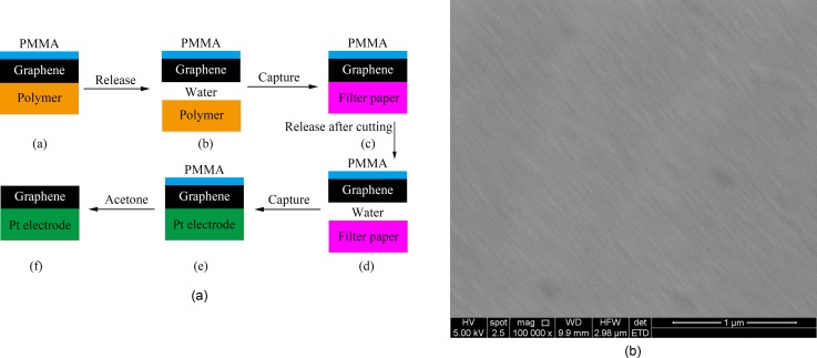
A single-layer graphene was transferred onto the WE surface in deionized water according to the procedures shown in Figure 3(a). First, the graphene product was released into the deionized water, which leads to the separation of the polymer. Next, the graphene was absorbed onto filter paper and cut into pieces of the desired shape and size. Then, the desired piece of graphene was released back to the water and captured with the cleaned WE. Finally, the PMMA layer was clarified with acetone. Figure 3(b) shows the SEM image of the transferred graphene on the WE surface.
FIG. 3.
(a) The procedures for graphene transfer. (b) Transferred graphene on the WE.
E. AuNPs modification on the graphene layer
To further enhance the sensitivity of the glucose sensor, AuNPs were used to improve the electron transfer rate between the activity center of GOx and the electrode. They were deposited onto the graphene layer on the WE, forming a composite nanostructured surface. Because they have special inherent features, such as a large surface-to-volume ratio, good electrocatalytic activity, and high chemical reactivity, the AuNPs have been applied in various biosensors.17 The AuNPs are particularly helpful in enhancing the sensitivity of the sensor by working as nanowires, thus improving the electron transfer between the activity center of GOx and the electrode. Moreover, the large surface-to-volume ratio of the AuNPs not only helps to immobilize GOx but also provides a large number of unsaturated bonds on the surface, making them more active. Consequently, the electrocatalytic activity and the chemical reactivity were intensified, contributing to the sensitivity of the sensor.
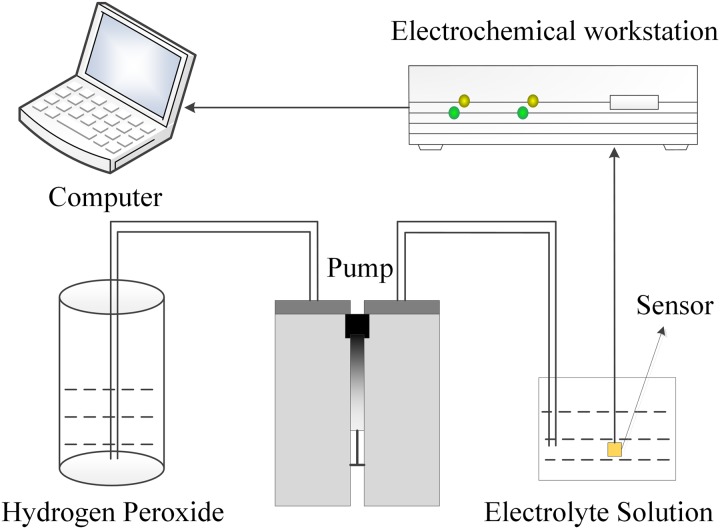
The AuNPs were directly decorated onto the graphene layer of the WE using an electrochemical deposition method, which makes it possible to easily control the size and distribution of the decorated AuNPs. An electrochemical setup, in which the target electrode served as the WE, a Pt sheet served as the CE, and an Ag/AgCl electrode served as the RE, was dipped into a plating solution consisting of HAuCl4 and 0.5 M Na2SO4 to electrodeposit the AuNPs onto the graphene layer. The AuNPs deposition was conducted using an electrochemical workstation. Constant current pulses were applied between the WE and the CE. Figure 4 shows the deposition system. As the concentration of HAuCl4, the deposition current, and the deposition time are key factors for the AuNPs modification, distinctive experiments were conducted to characterize the performance of the electrodes to obtain an optimized condition. We used H2O2 to test the sensor modified with AuNPs under various conditions before GOx was immobilized. The sensitivity and the linearity of the sensor were evaluated to obtain the optimized parameters for the AuNPs modification.
FIG. 4.
AuNPs deposition and electrochemical measurement system.
F. Immobilization of GOx on the WE surface
GOx was mixed with EDOT before it was immobilized onto the WE surface. The GOx/EDOT solution was prepared by first dissolving PSS (0.1 M) in deionized water. Next, EDOT (0.03 M) was added to the mixture with agitation. Then, the GOx dissolved in water was added to the mixture. The solution was used to electrochemically polymerize GOx (2 mg/ml) onto the composite nanostructured surface constraining graphene and AuNPs via constant current pulses that were applied between the WE and the CE.18 The immobilization of GOx onto the WE surface was performed using a method similar to that shown in Figure 4. The intensity of the polymerization current and the polymerization time dramatically affected the immobilization of GOx; thus, some experiments were conducted to characterize the performance of the glucose sensors immobilized GOx under different conditions. The sensitivity and the linearity of the glucose measurements were evaluated to determine the optimized parameters for the immobilization of GOx.
G. Integration of the glucose sensor into the ISF extraction microfluidic chip
After the proposed glucose sensor was fabricated, it was integrated into the PDMS-based ISF extraction microfluidic chip. As shown in Figure 5, the glucose sensor was bonded between the electrode layer and the flow sensor layer of the microfluidic chip, connected by the Access Port for Glucose Sensor (APGS). First, the two layers and the glucose sensor layer were treated with oxygen plasma for 25 s after the WE of the sensor was specifically protected to prevent damage to the immobilized GOx. Then, the glucose sensor layer was sandwiched at the correct position (APGS) between the two layers. The PDMS-based microfluidic chip is flexible, which makes a good connection to the skin; this will significantly reduce the influence caused by the relative motion between the device and the skin. Although the glucose sensor that was fabricated on glass is rigid, it is much smaller than the size of the ISF extraction microfluidic chip. Thus, the microfluidic chip integrated with the proposed electrochemical glucose sensor can be used to transdermally extract, dilute, and collect the ISF, while detecting the glucose concentrations in the ISF in the form of a wearable device for continuous glucose monitoring.
FIG. 5.
Photo of the microfluidic chip with the integrated electrochemical glucose sensor.
III. RESULTS AND DISCUSSION
A. Effect of graphene on the glucose sensor
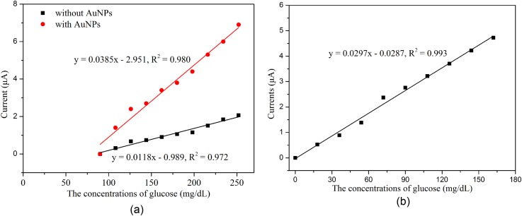
Graphene was transferred onto the WE surface to improve the electroactive nature and obtain a more uniform distribution of electrochemically active sites on the electrodes to enable measurements of low levels of glucose. The glucose sensors with and without graphene were characterized after GOx immobilization using the amperometric technique. The experiments were conducted by successively increasing 18 mg/dl glucose at an applied potential of −0.6 V. Figure 6(a) demonstrates that the current signals of the reaction with low levels of glucose (0–90 mg/dl) cannot be distinguished by the sensors with or without AuNPs if graphene is absent, while it can be well identified when graphene is present, as shown in Figure 6(b). This indicates that graphene provides significantly benefit for the detection of low levels of glucose.
FIG. 6.
Results of the measurement with different glucose sensors: (a) With and without AuNPs when graphene is absent and (b) with graphene and AuNPs.
B. AuNPs enhancement on the electrochemical sensor
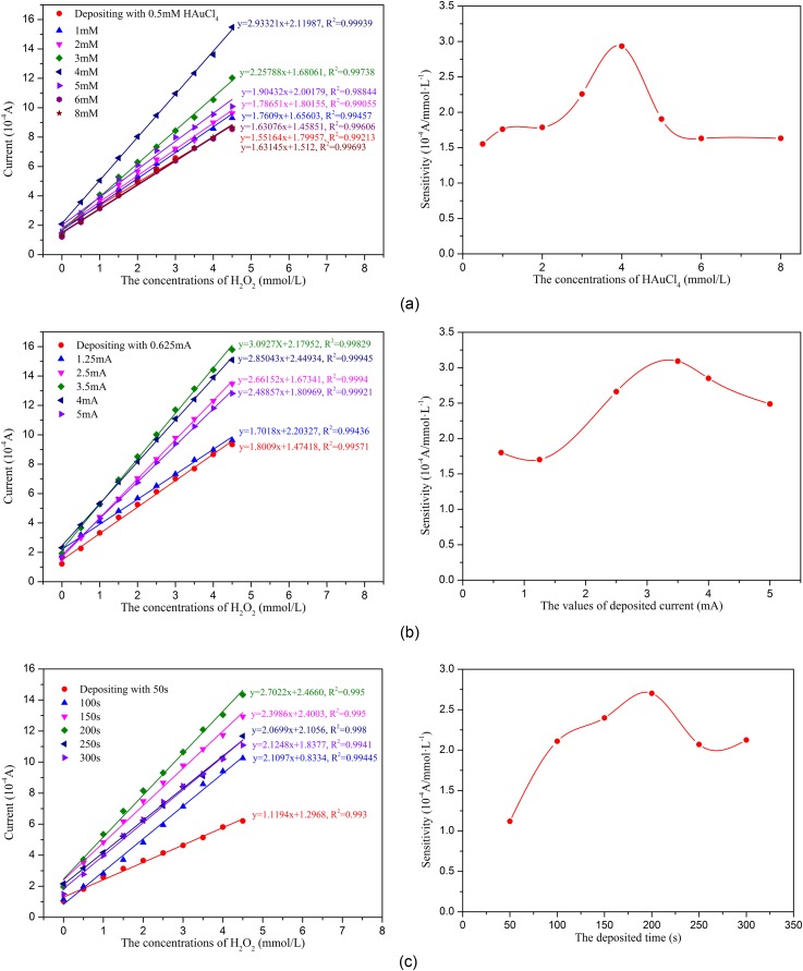
To evaluate the effects of the different AuNPs modification conditions on the sensor's ability to detect H2O2, the sensors modified with AuNPs on the WE surface were first tested using the amperometric technique. Figure 7 shows the typical amperometric responses of the various sensor configurations to successive increment of 0.5 mM H2O2 at an applied potential of −0.6 V. As shown in Figure 7, the electrochemical response increases as the H2O2 concentration increased, and all of the sensors demonstrate good linearity from 0 to 4.5 mM H2O2. Figure 7 also indicates that the concentration of HAuCl4, the deposition current intensity, and the deposition time significantly affect the AuNPs modification, which are expressed as a large change in the sensitivity of the sensors modified with AuNPs under different conditions. As shown in Figure 7, the optimized conditions for depositing the AuNPs on the sensor are as follows: 4 mM HAuCl4, a 10 mA/cm2 (3.5 mA) deposition current intensity, and a 200 s deposition time.
FIG. 7.
Characterization of the electrodes decorated with AuNPs under various conditions: (a) Concentrations of AuCl4, (b) current intensity, and (c) deposition time.
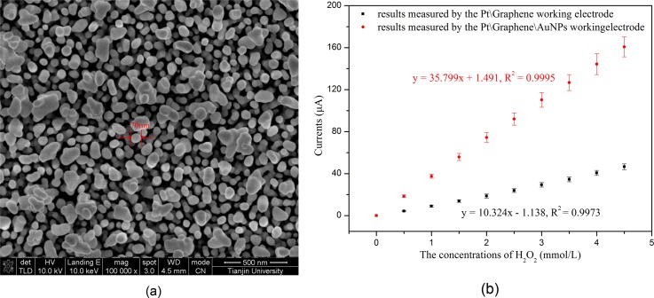
After obtaining the optimized parameters, the AuNPs were electrodeposited onto the graphene layer of the WE surface using these conditions. The SEM image of the AuNPs electrodeposited under the optimized conditions is shown in Figure 8(a). Then, H2O2 was employed to characterize the fabricated sensor before immobilizing GOx. As shown in Figure 8(b), the sensitivities of the sensors toward H2O2 were determined to be 36 μA/mM and 10 μA/mM for the sensors with and without AuNPs, respectively. This showed that a 3.6-fold enhancement of the sensor sensitivity was obtained by depositing AuNPs onto the graphene layer, which suggested that the deposited AuNPs can significantly improve the sensitivity of our sensor.
FIG. 8.
(a) The SEM image of the AuNPs modified under the optimal conditions and (b) H2O2 measurements using the sensor modified with and without AuNPs before immobilizing GOx.
C. Evaluation of the glucose sensor after the immobilization of GOx
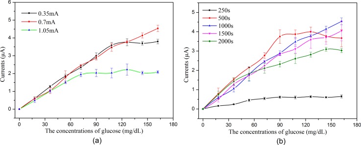
Figure 9 shows the typical amperometric responses of the various sensor configurations to successive increment of 18 mg/dl glucose at an applied potential of −0.6 V, which indicates that the polymerization current intensity and the polymerization time significantly affect the immobilization of GOx, which is expressed as a big change in the sensitivity and the linearity of the sensors under different conditions.
FIG. 9.
Glucose measurements using the sensor immobilized with GOx under the different conditions (n = 6): (a) Polymerization current intensities and (b) polymerization times.
Figure 9 shows that the linear range is narrow when the polymerization current is high/low or the polymerization time is too long/short. When the current is low or the time is too short, the amount of immobilized GOx is small, which restricts the linear range of glucose detection. When the current is high or the time is too long, an exorbitant polymer is constructed, which hinders the electrons transfer between the activity center of GOx and the WE. Moreover, the constructed exorbitant polymer may also hinder the diffusion of glucose through the polymer net. Both will limit the linear range of glucose detection. As shown in Figure 9, the optimized conditions for GOx immobilization are a 2 mA/cm2 (0.7 mA) polymerization current intensity and a 1000 s polymerization time.
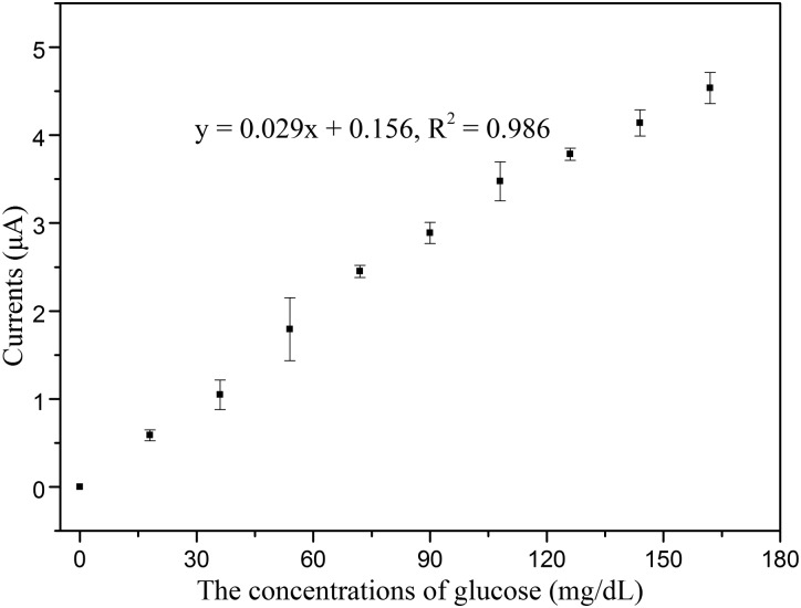
Figure 10 shows the amperometric responses of the fabricated sensor to successive increment of 18 mg/dl glucose at an applied potential of −0.6 V after immobilizing GOx under the optimized conditions. The linearity of glucose measurement by the fabricated glucose sensor is 0–162 mg/dl, with detection limit of 1.44 mg/dl (S/N = 3), which demonstrates that the electrochemical glucose sensor has the potential to detect hypoglycemia. In addition, the WE of the proposed sensor was flushed by PBS to clear the remaining glucose before it was re-used for the next measurement. The WE could be re-used after being flushed with PBS because the GOx was tightly immobilized on the WE surface.
FIG. 10.
Glucose measurements using the sensor with all of the surface modification under the optimized conditions (n = 6).
D. Selectivity and the response time of the glucose sensor
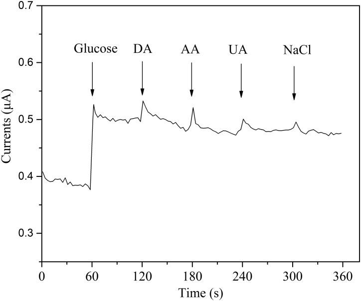
The selectivity of the sensor was evaluated by adding interference species, including dopamine (DA), ascorbic acid (AA), uric acid (UA), and sodium chloride (NaCl), to the determinand solution.19 As shown in Figure 11, the experimental result demonstrates that the proposed sensor exhibits good selectivity for glucose, and that the proposed sensor has the potential to detect glucose concentrations in the extracted ISF. The immobilized GOx enables the specific detection of glucose and significantly decreases the interference by the other species. Additionally, as shown in Figure 11, we can see that the response time is less than 1 s when the glucose concentration is changed, which demonstrates that the proposed sensor quickly reacted to the glucose concentrations.
FIG. 11.
The selectivity and the response time of the glucose sensor (the addition of different analytes in 0.1 M PBS: 0.2 mM glucose, 0.1 mM dopamine (DA), 0.1 mM ascorbic acid (AA), 0.1 mM uric acid (UA), and 0.1 mM NaCl).
E. Future utility of the presented microfluidic system
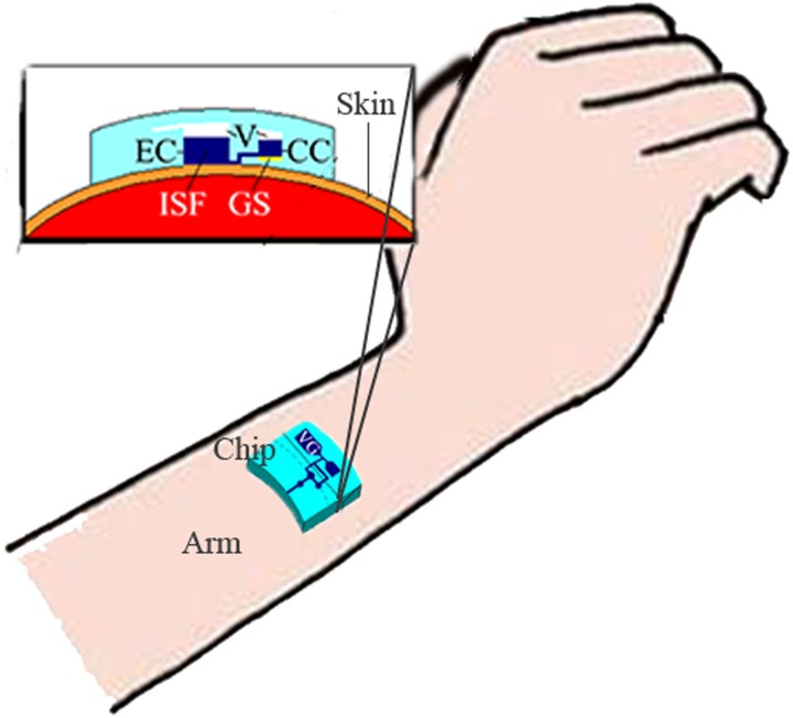
The proposed microfluidic system can be worn on the surface of the skin, which has been pretreated by low-frequency ultrasound, similar to a watch for continuous glucose monitoring, as shown in Figure 12. When low-frequency ultrasound is used to pretreat the skin, some micro pores open in the skin and the effect is maintained for approximately 48 h. Thus, a continuous glucose monitoring by the proposed microfluidic system can be achieved during the 48-h periods, without any other treatment for the skin. However, humans can assume different positions and each person has different skin properties, which leads to the different effects of the ultrasound pretreatment. This challenge could be addressed by a closed-loop system to dynamically control the ultrasound treatment. Additionally, the treated area must be continuously covered by the microfluidic chip to avoid potential infection through the open pores during the 48-h monitoring periods.
FIG. 12.
Schematic diagram for the application of the proposed microfluidic system. EC: extraction chamber, CC: collection chamber, V: vacuum, GS: glucose sensor, and VG: vacuum generator.
IV. CONCLUSION
This paper presented a continuous glucose monitoring microsystem consisting of an electrochemical sensor integrated into a microfluidic chip. The microfluidic chip was fabricated from five PDMS layers using micromolding techniques. The electrochemical sensor was integrated into the ISF extraction chip to form a device suitable for wearable continuous glucose monitoring. Graphene was transferred onto the WE surface to improve the electroactive nature of the electrode to enable measurements of low levels of glucose. The AuNPs were directly electrodeposited onto the graphene layer to improve the electron transfer rate from the activity center of the enzyme to the electrode to enhance the sensitivity of the sensor. Finally, GOx was immobilized onto the composite nanostructured surface by electrochemical polymerization to specifically detect glucose. Additionally, the factors required for AuNPs deposition and GOx immobilization were also investigated, and the optimized parameters were obtained. The experimental results demonstrated that the proposed sensor could precisely measure glucose in the linear range from 0 to 162 mg/dl, with a detection limit of 1.44 mg/dl (S/N = 3). The proposed sensor exhibited the potential to detect hypoglycemia in clinics.
ACKNOWLEDGMENTS
This work was supported by the National Natural Science Foundation of China (Nos. 61428402 and 81571766), the Key Projects in the Science & Technology Pillar Program of Tianjin (No. 11ZCKFSY01500), the Key Projects of Tianjin Natural Science Foundation Program (No. 15JCZDJC36100), the National High Technology Research and Development Program of China (No. 2012AA022602), and the 111 Project of China (No. B07014).
References
- 1. Heo Y. J. and Takeuchi S., Adv. Healthcare Mater. 2, 43 (2013). 10.1002/adhm.201200167 [DOI] [PubMed] [Google Scholar]
- 2. Safavieh R., Roca M. P., Qasaimeh M. A., Mirzaei M., and Juncker D., J. Micromech. Microeng. 20, 306 (2010). 10.1088/0960-1317/20/5/055001 [DOI] [Google Scholar]
- 3. Kovatchev B. P., Shields D., and Breton M., Diabetes Technol. Ther. 11, 139 (2009). 10.1089/dia.2008.0044 [DOI] [PMC free article] [PubMed] [Google Scholar]
- 4. Yu H., Li D., Roberts R. C., Xu K., and Tien N. C., J. Microelectromech. Syst. 21, 917 (2012). 10.1109/JMEMS.2012.2192910 [DOI] [Google Scholar]
- 5. Schoellhammer C. M., Polat B. E., Mendenhall J., Maa R., Jones B., Hart D. P., Langer R., and Blankschtein D., J. Controlled Release 163, 154 (2012). 10.1016/j.jconrel.2012.08.019 [DOI] [PMC free article] [PubMed] [Google Scholar]
- 6. Boaz M., Hellman K., and Wainstein J., Diabetes Technol. Ther. 11, 181 (2009). 10.1089/dia.2008.0048 [DOI] [PubMed] [Google Scholar]
- 7. Becher H., Lab Chip 11, 1571 (2011). 10.1039/c1lc90025k [DOI] [PubMed] [Google Scholar]
- 8. Zimmermann S., Fienbork D., Flounders A. W., and Liepmann D., Sens. Actuators, B 99, 163 (2004). 10.1016/S0925-4005(03)00552-5 [DOI] [Google Scholar]
- 9. Huang X., Li S., Schultz J., Wang Q., and Lin Q., J. Microelectromech. Syst. 18, 1246 (2009). 10.1109/JMEMS.2009.2034869 [DOI] [PMC free article] [PubMed] [Google Scholar]
- 10. Tierney S., Falch B. M. H., Hjelme D. R., and Stokke B. T., Anal. Chem. 81, 3630 (2009). 10.1021/ac900019k [DOI] [PubMed] [Google Scholar]
- 11. Tashkhourian J., Hormozi-Nezhad M. R., Khodaveisi J., and Dashti R., Sens. Actuators, B 158, 185 (2011). 10.1016/j.snb.2011.06.002 [DOI] [Google Scholar]
- 12. Siegrist J., Kazarian T., Ensor C., Joel S., Madou M., Wang P., and Daunert S., Sens. Actuators, B 149, 51 (2010). 10.1016/j.snb.2010.06.031 [DOI] [Google Scholar]
- 13. Yu H., Li D., Roberts R. C., Xu K., and Tien N. C., J. Micromech. Microeng. 22, 35010 (2012). 10.1088/0960-1317/22/3/035010 [DOI] [Google Scholar]
- 14. Shan C., Yang H., Han D., Zhang Q., Ivaska A., and Niu L., Biosens. Bioelectron. 25, 1070 (2010). 10.1016/j.bios.2009.09.024 [DOI] [PubMed] [Google Scholar]
- 15. Neto A. H. C., Guinea F., Peres N. M. R., Novoselov K. S., and Geim A. K., Rev. Mod. Phys. 81, 109 (2009). 10.1103/RevModPhys.81.109 [DOI] [Google Scholar]
- 16. Maharana P. K. and Jha R., Sens. Actuators, B 169, 161 (2012). 10.1016/j.snb.2012.04.051 [DOI] [Google Scholar]
- 17. Saei A. A., Dolatabadi J. E. N., Najafi-Marandi P., Abhari A., and Guardia M., TrAC-Trend Anal. Chem. 42, 216 (2013). 10.1016/j.trac.2012.09.011 [DOI] [Google Scholar]
- 18. Claussen J. C., Kumar A., Jaroch D. B., Khawaja M. H., Hibbard A. B., Porterfield D. M., and Fisher T. S., Adv. Funct. Mater. 22, 3399 (2012). 10.1002/adfm.201200551 [DOI] [Google Scholar]
- 19. Liu M., Liu R., and Chen W., Biosens. Bioelectron. 45, 206 (2013). 10.1016/j.bios.2013.02.010 [DOI] [PubMed] [Google Scholar]


