Abstract
PURPOSE
This in vitro study investigated and compared the durability and retention of three types of attachments.
MATERIALS AND METHODS
Three commercially available attachments were investigated: Clix®, Dalbo-Plus® and Locator®. In total, 72 samples of these attachments were placed in the acrylic resin forms and subjected to mechanical testing (5400 cycles of insertion and removal) over the respective ball or Locator abutments immersed in artificial saliva at pH 7 and 37℃. The abutments were placed at angulations of 0°, 10° and 20°. The retention force was recorded at the beginning and after 540, 1080, 2160, 3240, 4320 and 5400 insertion-removal cycles.
RESULTS
The results revealed that there were significant differences in the average values of the insertion/removal force due to angulation (F (2.48) = 343619, P<.05) and the type of attachment (F (7.48) = 23.220, P<.05).
CONCLUSION
Greater angulation of the abutments was found to influence the retention capacity of the attachments, and the fatigue test simulating 5 years of denture insertion and removal did not produce wear in the metal abutments.
Keywords: Dental implants, Edentulous patients, Overdentures, Attachments
INTRODUCTION
Many types of attachment systems are currently available to retain overdentures. The purpose of these systems is to improve denture retention. However, in clinical settings, some problems have been found in certain types of attachment used, such as early loss of rertention that leads to increase in the cost of treatment. A consensus statement from McGill University and the British Society for the Study of Prosthetic Dentistry determined that a two-implant overdenture should be the first choice of treatment for an edentulous mandible, and implant overdentures have become more popular.1,2 Moreover, with the insertion of implants, bone resorption has dramatically decreases when compared with conventional denture use.3,4 The attachment systems used in implant-supported overdentures have different retentive capacities and have either a bar attachment (splinted attachment system) or a conjunct of different unsplinted systems, such as spherical/ball types, magnets, telescopic crowns or stud-type attachments.5 The success of an implant-retained overdenture primarily depends on the retentive capacity of its attachment element to sustain its long-term functionality.6 A combination of metal-metal or metal-plastic/nylon contacts is normally used in an attachment system.5 The aim of this in vitro study was to evaluate the durability of and variations in the retention force of three implant overdenture stud-type attachment systems at three different angulations in an aqueous environment of artificial saliva. The retention force was measured at the beginning and after 540, 1080, 2160, 3240, 4320 and 5400 insertion-removal cycles.
MATERIALS AND METHODS
Three commercial attachment systems were selected for the study: Clix®, Dalbo-Plus® and Locator®. The experimental groups were divided into red and yellow Clix attachments; Dalbo-Plus; and white, pink, blue, green, and red Locator attachments. Nine new samples for each group, provided in their original containers, were evaluated with 3 samples for each angulation, resulting in a total of 72 samples.
The artificial saliva used in this study was produced in the laboratory according to a previous study.7
The female component of each sample, in its original container, was incorporated into a small acrylic cylinder to simulate its location at the base of prosthesis. This was achieved by placing a mixture of thermopolymerizable acrylic (megaCRYL® N, Megadental, Germany) into acrylizing forms specifically designed to be incorporated into the test machine, CS-Dental Testing Machine and Pan Placement, for 10 to 15 min at 2 bars of pressure. A ratchet with the torque device and the corresponding adaptors of the abutments were used to incorporate corresponding implant analogues with a final torque of 20 N. The samples were placed into metallic forms specifically designed for the machine with angulations of 0°, 10° and 20° (Fig. 1).
Fig. 1. Female (A) and male (B) supports at angulations of 0° (B), 10° (C) and 20° (D).
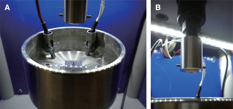
The abutment and the attachments were placed inside the two pieces designed specifically for this machine (Fig. 2). The CS-Dental Testing Machine® has been described by Sergio Silva (2015).7 The testing machine was programmed with a working crosshead speed of 1.06 mm per second, which was produced by an electric motor with 0.2 KW. A load cell with a measuring range of ± 30000 gf was used to register the forces. After following the driving and calibration protocols to test the machine, 5400 insertion-removal cycles were performed to simulate 5 years of wear, and the wear (removal/insertion values) was registered at 8 different time points (initial, 1 month, 6 months, 1 year, 2 years, 3 years, 4 years, and 5 years). All samples were immersed in artificial saliva at pH 7 and 37℃ during the test to simulate oral conditions. The temperature was programmed at 37℃ and controlled automatically by a thermal resistance of 100 W and a sounding of PT100. Data were collected using a pen drive in a USB port in the machine. Each file registered approximately 250,000 read points transmitted by the load cell. An Excel spreadsheet was used to select the desired cycles for this study. The surface characteristics were also evaluated using a microscope stereoscope (Olympus SZ61, Tokyo, Japan) with a 90× magnifier and a digital camera incorporated into the microscope.
Fig. 2. Samples inside the CS Dental Machine. Male (A) immersed in artificial saliva and Female (B) inside the metallic form.
All statistical analyses were performed using IBM® SPSS® Statistics software version 22.0 (SPSS Inc., Chicago, IL, USA), and P < .05 was considered statistically significant.
In order to assess the influence of the angulation and attachment factors on the average value of the insertion force at the eight evaluated times, ANOVA with repeated measures was performed.
Taking into account the experimental design, for an alpha value of 0.05, a power of 0.95, and a square eta of 0.5 (f = 1.0, effect size) and using a threshold value for correcting the nonsphericity used, the program G * Power 3.1.9.28 indicates the minimum required value for the global sample to be 54.
If we consider n = 72, the calculation made using G * Power 3.1.9.28 reduces the effect size to 0.616, keeping the other parameters unchanged.
The assumption of normality was assessed using the Shapiro-Wilk test with P > .05 for all evaluated time points according to the angulations and the type of attachments.
The assumption of sphericity was tested with Mauchly's test (P < .05), which rejected the sphericity of the data. Because the estimated value of epsilon was less than 0.75, a Greenhouse-Geisser correction was used for the interpretation of the results for intra-subject effects.
RESULTS
The retention forces of the three types of attachments were evaluated by analyzing the values of the insertion and removal independently. The values were expressed in gf.
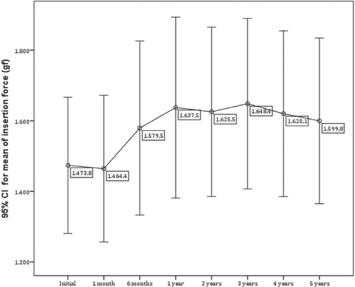
An analysis of the results revealed that there were significant differences in the average value of the insertion force at different time points; that is, there was a significant variation in the average value of the insertion force over time, and this value increased significantly over time (Fig. 3).
Fig. 3. Insertion force average over time.
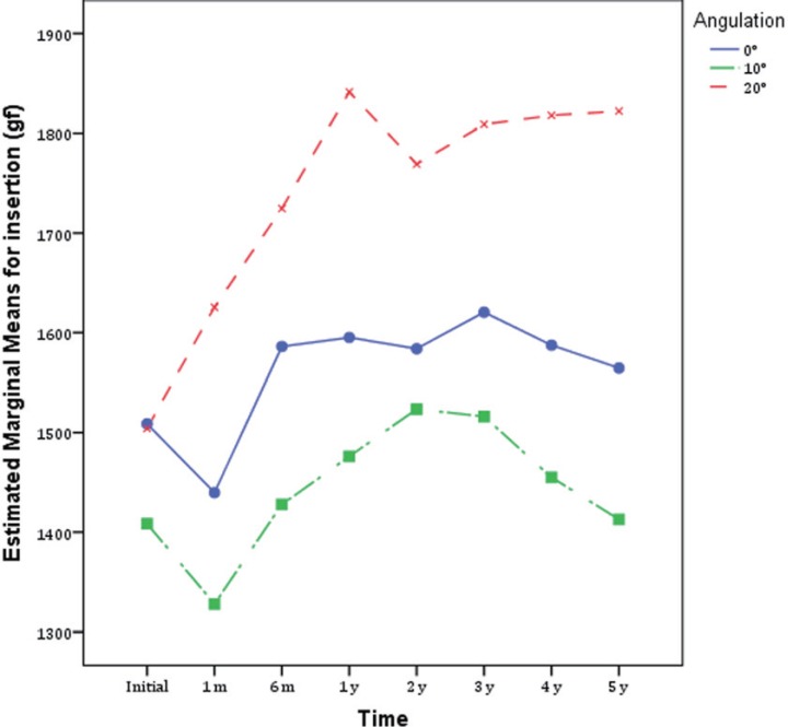
There were no significant differences in the average value of the insertion force due to the interaction of time and angulation (F (3.866; 92.791) = 0.870, P > .05), indicating that the group averages (angulations of 0°, 10≥ and 20≥) were identical to the eight evaluated times. These findings are reflected by the parallel lines in Fig. 4.
Fig. 4. Insertion force averages for the different angulations.
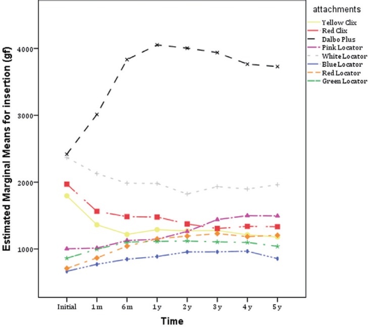
There were significant differences in the average value of the insertion force due to the interaction of time and attachment (F (13.532; 92.791) = 8.161, P < .05), indicating that the group averages (Clix, Locator and Dalbo-Plus) were different at the eight evaluated times; that is, the average value of the insertion force was not the same for the three different attachments. These findings are reflected by the lack of parallel lines in Fig. 5.
Fig. 5. Insertion force averages for the different attachments.
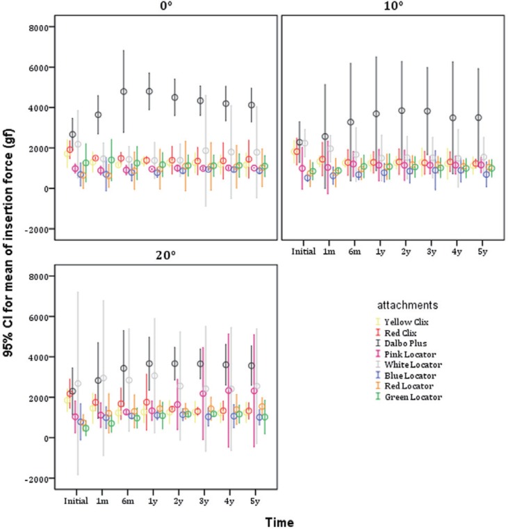
There were no significant differences in the average value of the insertion force due to the interaction of time with angulation and attachment (F (27.064; 92.791) = 1.279, P > .05), indicating that the average group values were identical at the eight evaluated times (Fig. 6).
Fig. 6. Insertion force averages for the different attachments at angulations of 0°, 10°, and 20°.
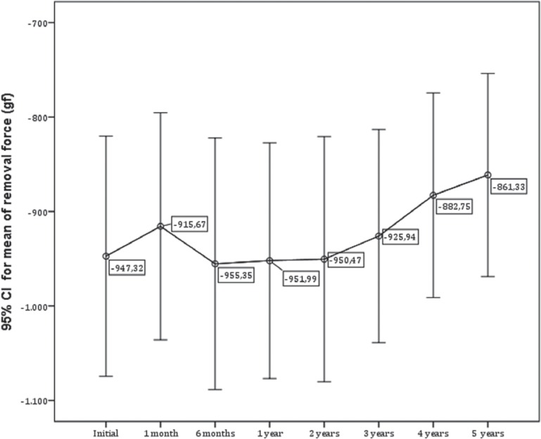
An analysis of the results revealed that there were significant differences in the average value of the removal force at the different time points; that is, there was a significant variation in the average value of the removal force over time, and this value decreased significantly over time (Fig. 7).
Fig. 7. Removal force average over time.
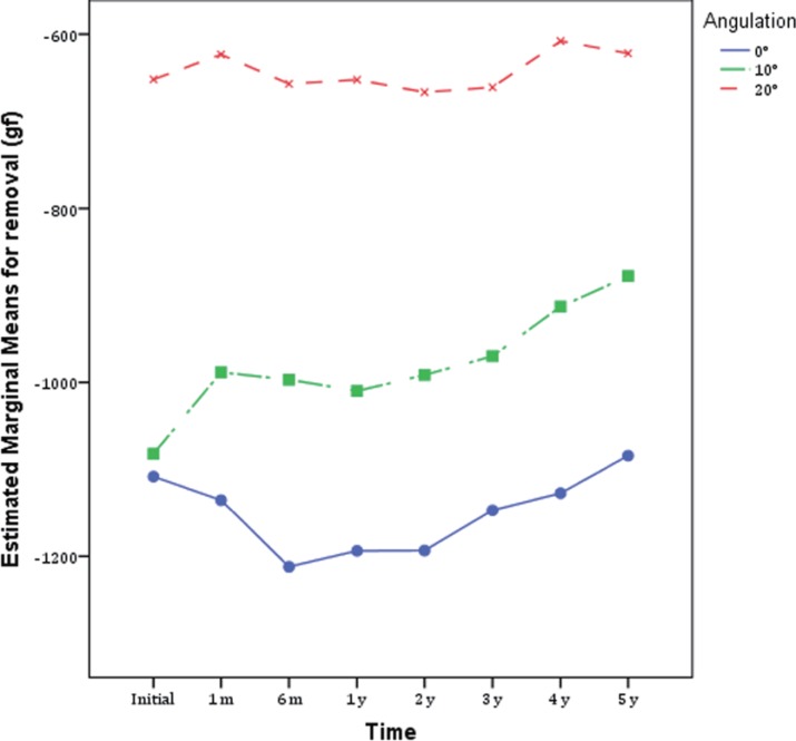
There were no significant differences in the average value of the removal force due to the interaction of time and angulation (F (5.978; 143.467) = 1.499, P > .05), indicating that the group averages (angulations of 0°, 10° and 20°) were identical at the eight evaluated times. These findings are reflected by the parallel lines in Fig. 8.
Fig. 8. Removal force averages for the different angulations.
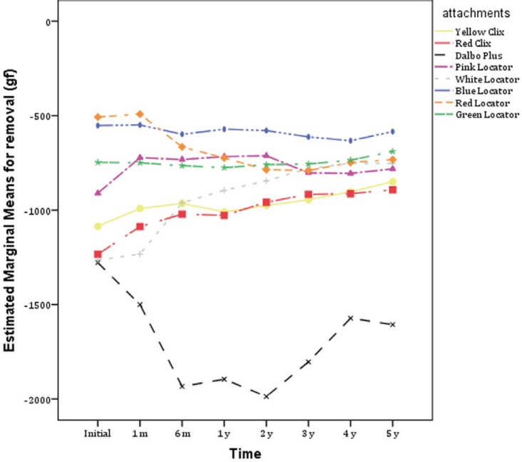
There were significant differences in the average value of the removal force due to the interaction of time and attachment (F (20.922; 143.467) = 8.053, P < .05), indicating that the group averages (Clix, Locator and Dalbo-Plus) were different at the eight evaluated times; that is, the average value of the removal force was not the same for the three different attachments. These findings are reflected by the lack of parallel lines in Fig. 9.
Fig. 9. Removal force averages for the different attachments.
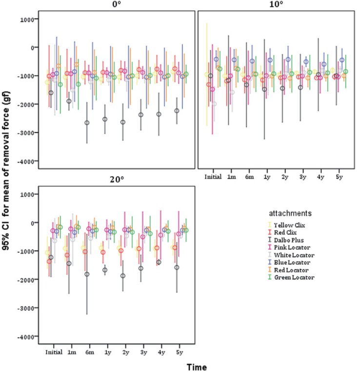
There were significant differences in the average value of the removal force due to the interaction of time with angulation and attachment (F (41.845; 143.467) = 2.010, P < .05), indicating that the average group values were not identical at the eight evaluated times (Fig. 10).
Fig. 10. Removal force averages for the different attachments at angulations of 0°, 10°, and 20°.
The percentage of retention loss in the removal force was evaluated and compared to the baseline measurement. Negative values indicated gains in removal force because this force was evaluated in negative numbers, meaning that the recorded data in the machine test presented positive numbers for the insertion force and negative numbers for the removal force (Table 1).
Table 1. Percentage of loss of retention in removal force compared to baseline.
| Attachments | ||||||||||
|---|---|---|---|---|---|---|---|---|---|---|
| Yellow Clix | Red Clix | Dalbo-Plus | Pink Locator | White Locator | Blue Locator | Red Locator | Green Locator | |||
| Angulation | 0° | 1 month | 14.8% | 9.4% | -18.4% | 2.9% | -30.4% | 7.0% | 7.8% | 0.6% |
| 6 months | 16.2% | 12.0% | -65.9% | 6.1% | -5.4% | -9.4% | -34.9% | 17.0% | ||
| 1 year | 9.2% | 13.3% | -58.1% | 7.3% | 0.4% | -2.4% | -47.4% | 19.4% | ||
| 2 years | 15.4% | 19.9% | -64.5% | 12.6% | 1.8% | -13.4% | -56.0% | 23.5% | ||
| 3 years | 19.2% | 22.7% | -48.4% | 7.6% | 12.0% | -14.2% | -61.3% | 24.4% | ||
| 4 years | 24.9% | 24.4% | -47.1% | 6.3% | 14.4% | -13.5% | -56.3% | 23.9% | ||
| 5 years | 30.4% | 25.7% | -39.6% | 6.4% | 17.9% | -12.0% | -51.3% | 28.1% | ||
| 10° | 1 month | -5.3% | 9.2% | -15.6% | 31.9% | 20.5% | -4.7% | -2.2% | -1.2% | |
| 6 months | -0.6% | 12.8% | -31.7% | 27.6% | 44.6% | -15.1% | -30.0% | -23.6% | ||
| 1 year | -5.4% | 12.1% | -47.6% | 32.6% | 48.1% | -7.1% | -40.9% | -22.2% | ||
| 2 years | -2.4% | 18.2% | -44.2% | 29.4% | 53.3% | -1.5% | -51.2% | -22.2% | ||
| 3 years | 4.8% | 20.5% | -41.4% | 31.5% | 55.0% | -20.8% | -49.5% | -15.8% | ||
| 4 years | 9.8% | 17.9% | 4.0% | 27.6% | 58.9% | -40.8% | -40.2% | -18.1% | ||
| 5 years | 16.0% | 20.9% | 0.4% | 29.5% | 58.6% | -6.0% | -38.7% | -11.6% | ||
| 20° | 1 month | 14.1% | 16.3% | -17.5% | 21.4% | 6.0% | -11.4% | 8.0% | -3.2% | |
| 6 months | 15.8% | 25.2% | -48.2% | 22.9% | 12.9% | 3.8% | -20.0% | -56.8% | ||
| 1 year | 15.7% | 23.5% | -36.2% | 9.5% | 22.2% | -1.9% | -29.8% | -102.2% | ||
| 2 years | 15.2% | 27.9% | -52.9% | 12.5% | 27.0% | 15.9% | -68.5% | -104.6% | ||
| 3 years | 12.8% | 32.8% | -31.4% | -75.7% | 34.0% | 12.4% | -62.0% | -135.0% | ||
| 4 years | 13.8% | 34.8% | -13.8% | -53.9% | 30.4% | 18.0% | -42.0% | -84.6% | ||
| 5 years | 17.5% | 35.5% | -28.8% | -39.3% | 24.8% | 12.7% | -41.3% | -63.8% | ||
Before and after being subjected to 5400 cycles of insertion and removal, all the attachments and abutments were observed with a stereoscope (Olympus SZ61) and 90× magnifier to evaluate any changes in their surfaces. The diameters of the abutments were also measured with a digital micrometer to evaluate any changes.
Regarding the metal abutments, there were no differences in the values of their diameters before and after the 5400 cycles of insertion and removal. The ball abutments had an average value of approximately 2.25 mm, and the locator abutments had an average value of 3.86 mm.
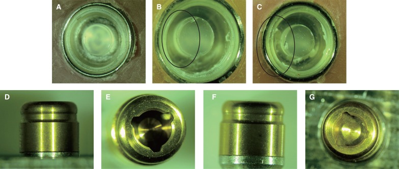
No visible wear was detected in the surfaces of the abutments. However, in the female components, some apparent deformation was detected, particularly in the internal part of the white, pink and blue Locators (Fig. 11).
Fig. 11. White Locator samples (A in initial and B, C at the end) and abutment (D, E in initial and F, G at the end) before and after the 20° test.
DISCUSSION
In this in vitro study, 5400 cycles were used to simulate an in vivo function of 5 years based on an average of 3 removal-insertions of the overdentures per day for oral hygiene procedures.9 The use of artificial saliva is the standard in in vitro studies to simulate wear and to promote lubrication of the attachment components.10,11,12 These types of tests are commonly used to obtain important information. Attachment retention forces of 5 to 20 N are sufficient to provide retention in overdentures.13,14,15,16 The three commercial attachments investigated allow an easy exchange of the female parts when the tool indicated by the manufacturer is used. This parameter is in agreement with the studies of Cohen et al.17 and Trakas et al.18.
In both the yellow and red Clix samples at an angulation of 0°, the retention force decreased over time from an initial value of 862 gf and 8.45 N by 30.40% (1238 gf - 12.14 N) in the yellow Clix and by 25.70% (754 gf - 7.4 N) in the red Clix. In the red Clix sample, it was verified that a larger angulation required more strength of removal force at an angulation of 20°, and the initial retention force was greater (1373 gf - 13.47 N), but over time, the loss of retention force was also higher, with values of 35.5% (886 gf - 8.68 N) at an angulation of 20° compared to a loss of 20.90% (1037 gf - 10.16 N) at an angulation of 10°.
Ortegón et al.19 used Preci-Clix attachments over implants with different angles between the matrix and patrix according to the axis of insertion at an angulation of 0°. Test groups combined a matrix and patrix of 0°, 10° and 15° and after 3,500 fatigue cycles and found that these inclinations had influence over time in the retention force and that at an angulation of 10°, the retention force was lower than at an angulation of 15°. Our results showed that in the Clix group, the angulation of the abutments influenced the retention force, which means that more angulation required more retention force, but over time, the loss is greater. However, the final value of the retention force is acceptable to retain an overdenture.
All the samples of Dalbo-Plus system presented initial retention forces adequate to retain an overdenture. The initial mean values for removal force varied from 1003.70 gf (9.83 N) to 1602.30 gf (15.71 N) depending on the angulation. The Dalbo-Plus system presented a greater insertion force over time. There were significant differences in the mean values of removal force due to the interaction of time with angulation and type of attachment (F (41.845; 143.467) = 2.010, value P < .05), indicating that the group averages were different at the eight evaluated times. According to the results of the test on the effects of the factors, it was verified that there are significant differences in the mean value of the removal force due to angulation (F (2.48) = 34.619, value P < .05), type of attachment (F (7.48) = 23.220, P-value < .05), and interaction (F (14) (0.48) = 5.209, value P < .05).
The Dalbo-Plus system presented gains in insertion and removal forces throughout the study, unlike the results from other published studies on angulation. Gains of 39.60 gf (21.92 N) have been verified at an angulation of 0° and of 28.80% (15.50 N) at an angulation of 20°. At an angulation of 10°, there was a slight increase in the removal force. Despite these gains, the removal forces by the end of the study were at the maximum values recommended by the manufacturer of this system (21 N). Gains of 50.00% have been verified in the insertion force. Similar results were found by Kobayashi5 for the retention force in the Dalbo-Plus system. Mean values in the removal force of 67.9 ± 15.83 N have been found in a stocking system, with a gain of 83 N above the initial value of 40.3 ± 15.83 N. At an angulation of 20°, the system has the same behavior.
Bayer et al.20 studied large fluctuations in the retention force in this attachment. These fluctuations may have been caused by the elasticity of the titanium or gold lamellae that was mounted with little space between it and the matrix, which leads to a crash during the separation movement. However, they had a loss of retention force over time that was in contrast to our findings.20 They obtained an increase in the mean value of the retention force in the first 500 cycles, but at 2000 cycles, they obtained a value of 5 N. Fakhry et al.21 obtained increases in the initial mean values of retention forces, followed by a gradual decrease over 10000 cycles. A minimum change in the mean value of the retention force was found at an angulation of 20° between the attachments and the abutments did not have a negative effect on the retention force.
In the Locator system, initial retention forces that were different from those indicated by the manufacturer were found. While the color-coding indicated different levels of retention according to the manufacturer, the initial mean values for the pink and blue samples were all very similar (9.42 N and 9.03 N). The values below those indicated by the manufacturer were found in the pink, white, green, blue and red samples. These differences were also seen in the study by Rutkunas et al.,22 who found initial average values of insertion forces to be similar among the pink (15.20 N), white (16.61 N) and blue (16.50 N) samples that were different from those recommended by the manufacturer. Chen et al.,23 in a study of the rotational movement of attachments, also referred to differences between the initial values of retention force in these groups and those indicated by the manufacturer. This finding can be explained by small differences that may occur during the manufacturing process.24 According to the manufacturer, the pink Locator is designed with an abutment placed at an angulation of between 0° and 10°. There is a significant loss of retention force, with an average value of 6.4% for an angulation of 0° and 29.50% for an angulation of 10°. This loss has been referenced by some authors.22,25,26 However, at an angulation of 20°, a loss is verified at 3240 cycles, but there is an increase of 75.70% in the removal force compared to the initial value, followed by a decrease of approximately 39.30% by the end of the testing. This change found at an angulation of 20° indicates a flattening of the inner part of the Teflon, which leads to the need for greater insertion force. The consequent increase in the removal force causes the wear of this component that lead to a constant decline in the retention force. Changes in the morphology of the Teflon due to wear and friction during movement may change the value of the retention force.21,26
The white Locator presented the largest loss of retention at an angulation of 10°, with an average loss of 58.60% compared with the initial value. Approximately 17.90% of the retention loss was verified at an angulation of 0° and 24.80% at an angulation of 20°. However, values registered at the end of each test for each angulation were enough for the system to retain an overdenture. The removal force values were 949 gf (9.3 N) at 0°, 825.33 gf (8.10 N) at 10°, and 484.63 gf (4.75 N) at 20°. Although not indicated by the manufacturer, these results indicate that the pink and white Locators can work on abutments with angulations of 20°. The blue Locator results differed from those found in other studies because the blue Locator had gains in the removal force at angulations of 0° and 10° and a loss at an angulation of 20°. Increases of 12.00% and 6.00% in the mean values of removal force can be explained by the deformation of the Teflon and possible changes in its resilience. At an angulation of 20°, a loss of 12.70% was found, with average values of 273.03 gf (2.67 N) below those determined by the authors to be required to retain an overdenture.
Rutkunas et al.22 referred to a moderate increase in the value of removal force in the white, pink and blue Locators at the beginning of testing, but at the end of testing the loss was between 21% and 62% of the removal force (2.2-9.4 N).
According to the manufacturer, the red and green Locators should be used at angulations of 10° to 20°. These types of Teflon differ from others because they do not possess internal retention, based on their retentive capacity provided by the resilience of Teflon, or external retention over the abutment. Retention values higher than those indicated by the manufacturer were found in the red Locator samples (687.7 gf), and lower values were found in the green Locator samples (1311.3 gf). This may explain the discrepancies found in our results.
The red Locator samples had gains in the removal force at all angulations. Those gains were evident up to 3240 cycles and then progressively declined until 5400 cycles. At an angulation of 0°, a mean value of removal force of 996.70 gf (9.77 N) was obtained. At an angulation of 10°, gains were on the order of 38.70% with a mean value of 1001.67 gf (9.82 N), and at 20° the lowest values of removal force for this group were obtained, with a gain of 41.30% corresponding to 200.67 gf (1.96 N), which is insufficient to retain an overdenture. We think that the origin of these values was the composition of the Teflon, which would have little resistance because despite obtaining insertion force values of 742.33 force gf (7.27 N) at the beginning and 1543.66 gf (15.13 N) at the end of the study, the removal force at an angulation of 20° was very low. The green Locator behaved in a similar manner to the red Locator, losing removal force over time at an angulation of 0°, but gaining force at angulations of 10° and 20°, although at values too low to retain an overdenture. The mean value in the removal force at an angulation of 20° was 273,03 gf (2.67 N) at the end of the study, which was clearly lower than that referenced by different authors to retain an overdenture.10,14,15,16,27,28,29,30,31
In an in vitro study conducted by Uludag et al.32 of 3 implants at the middle level in canines with an angulation of 20°, the green Locator showed a loss of 20% in removal force at the end of 540 cycles but maintained average values that were adequate to retain an overdenture (47 N). Friction, water absorption and/or thermal expansion of Teflon can contribute to dimensional changes in plastic parts of attachments.22 By contrast, in the mouth, functional and parafunctional movements may cause deformation in the plastic parts, resulting in a decrease of removal force or even a rupture of the attachment. Discrepancies between clinical findings and in vitro fatigue tests indicate that wear cannot be adequately simulated by using the current in vitro approaches. The three dimensional movement of an overdenture during function, angulation of implants, effects of cleaning agents, food, aging of the plastic parts, and fatigue of the metal parts are indicated as possible causes of these disagreements. Currently, given the complexity of simulated clinical conditions, the results of in vitro studies should only serve as an empirical orientation.
The macroscopic analysis of the abutments was performed before and after testing with the use of a digital micrometer. No relevant macroscopic differences were found in the metal parts. The ball abutments had a mean diameter of 2.25 mm, and the Locator abutments had a mean diameter of 3.86 mm; there were no changes to either group as a result of the tests. Therefore, we can say that no wear of the metal abutments occurred. Metal waste in the abutments was not found, which would have confirmed some type of wear. All 72 attachments, 18 ball abutments, and 15 Locator abutments, which had previously been separated in individual boxes, were observed at the beginning and at the end of the test using a stereoscope (Olympus® SZ61) with enlargements of 90x and a camera (Olympus® SC30) built in for the registration and evaluation of wear produced during fatigue tests. A comparison of the initial and the final photos of each sample showed a small amount of wear (Fig. 11). In relation to angulation, a macroscopic deformation of specimens with areas of material loss was larger in samples at 20° than at 0°. The white Locator showed signs of wear on the inside as well as deformation of internal parts. Factors such as hardness, resilience or elasticity mode intrinsic to each material were fundamental to the wear observed in various combinations of attachments used throughout the study. Türk et al.33 evaluated samples by microscopy (SEM) after 5000 fatigue tests and found that the metal abutments did not show significant differences in their diameters, and no signs of wear were observed. The authors concluded that wear in metal parts could not be verified after 5000 cycles.33 Kobayashi et al.5 also concluded that the Dalbo-Plus and Locator systems showed no wear after 14600 cycles of insertion and removal.
CONCLUSION
Within the limitations of this study, the following conclusions were drawn: greater angulation of the abutment values was found to influence the retention capacity of the attachments, the attachment systems evaluated in this study presented adequate retention for clinical usage, the fatigue test simulating 5 years of denture insertion and removal did not produce wear in metal abutments. Overall, the Dalbo-Plus system provided the best retention followed by the white Locator system.
References
- 1.Feine JS, Carlsson GE, Awad MA, Chehade A, Duncan WJ, Gizani S, Head T, Lund JP, MacEntee M, Mericske-Stern R, Mojon P, Morais J, Naert I, Payne AG, Penrod J, Stoker GT, Tawse-Smith A, Taylor TD, Thomason JM, Thomson WM, Wismeijer D. The McGill consensus statement on overdentures. Mandibular two-implant overdentures as first choice standard of care for edentulous patients. Montreal, Quebec, May 24-25, 2002. Int J Oral Maxillofac Implants. 2002;17:601–602. [PubMed] [Google Scholar]
- 2.British Society for the Study of Prosthetic Dentistry. The York consensus statement on implant-supported overdentures. Eur J Prosthodont Restor Dent. 2009;17:164–165. [PubMed] [Google Scholar]
- 3.Tallgren A. The continuing reduction of the residual alveolar ridges in complete denture wearers: a mixed-longitudinal study covering 25 years. 1972. J Prosthet Dent. 2003;89:427–435. doi: 10.1016/s0022-3913(03)00158-6. [DOI] [PubMed] [Google Scholar]
- 4.de Jong MH, Wright PS, Meijer HJ, Tymstra N. Posterior mandibular residual ridge resorption in patients with overdentures supported by two or four endosseous implants in a 10-year prospective comparative study. Int J Oral Maxillofac Implants. 2010;25:1168–1174. [PubMed] [Google Scholar]
- 5.Kobayashi M, Srinivasan M, Ammann P, Perriard J, Ohkubo C, Müller F, Belser UC, Schimmel M. Effects of in vitro cyclic dislodging on retentive force and removal torque of three overdenture attachment systems. Clin Oral Implants Res. 2014;25:426–434. doi: 10.1111/clr.12156. [DOI] [PubMed] [Google Scholar]
- 6.Tabatabaian F, Saboury A, Sobhani ZS, Petropoulos VC. The effect of inter-implant distance on retention and resistance to dislodging forces for mandibular implant-tissue-supported overdentures. J Dent (Tehran) 2014;11:506–515. [PMC free article] [PubMed] [Google Scholar]
- 7.Silva AS, Aroso C, Ustrell R, Braga AC, Mendes JM, Escuin T. The influence of saliva pH value on the retention and durability of bar-clip attachments. J Adv Prosthodont. 2015;7:32–38. doi: 10.4047/jap.2015.7.1.32. [DOI] [PMC free article] [PubMed] [Google Scholar]
- 8.Faul F, Erdfelder E, Lang AG, Buchner A. G*Power 3: a flexible statistical power analysis program for the social, behavioral, and biomedical sciences. Behav Res Methods. 2007;39:175–191. doi: 10.3758/bf03193146. [DOI] [PubMed] [Google Scholar]
- 9.Branchi R, Vangi D, Virga A, Guertin G, Fazi G. Resistance to wear of four matrices with ball attachments for implant overdentures: a fatigue study. J Prosthodont. 2010;19:614–619. doi: 10.1111/j.1532-849X.2010.00613.x. [DOI] [PubMed] [Google Scholar]
- 10.Botega DM, Mesquita MF, Henriques GE, Vaz LG. Retention force and fatigue strength of overdenture attachment systems. J Oral Rehabil. 2004;31:884–889. doi: 10.1111/j.1365-2842.2004.01308.x. [DOI] [PubMed] [Google Scholar]
- 11.Queiroz GM, Silva LF, Ferreira JT, Gomes JA, Sathler L. Electrochemical behavior and pH stability of artificial salivas for corrosion tests. Braz Oral Res. 2007;21:209–215. doi: 10.1590/s1806-83242007000300004. [DOI] [PubMed] [Google Scholar]
- 12.Stüttgen U. Effect of saliva smears in experimental wear studies on precious and non-precious metal casting alloys. Zahntechnik (Zur) 1985;43:466–468. 470–471. [PubMed] [Google Scholar]
- 13.Caldwell RC. Adhesion of foods to teeth. J Dent Res. 1962;41:821–832. doi: 10.1177/00220345620410041401. [DOI] [PubMed] [Google Scholar]
- 14.Setz I, Lee SH, Engel E. Retention of prefabricated attachments for implant stabilized overdentures in the edentulous mandible: an in vitro study. J Prosthet Dent. 1998;80:323–329. doi: 10.1016/s0022-3913(98)70133-7. [DOI] [PubMed] [Google Scholar]
- 15.Walmsley AD. Magnetic retention in prosthetic dentistry. Dent Update. 2002;29:428–433. doi: 10.12968/denu.2002.29.9.428. [DOI] [PubMed] [Google Scholar]
- 16.Walmsley AD, Frame JW. Implant supported overdentures-the Birmingham experience. J Dent. 1997;25:S43–S47. doi: 10.1016/s0300-5712(97)87700-7. [DOI] [PubMed] [Google Scholar]
- 17.Cohen BI, Pagnillo M, Condos S, Deutsch AS. Comparative study of two precision overdenture attachment designs. J Prosthet Dent. 1996;76:145–152. doi: 10.1016/s0022-3913(96)90298-x. [DOI] [PubMed] [Google Scholar]
- 18.Trakas T, Michalakis K, Kang K, Hirayama H. Attachment systems for implant retained overdentures: a literature review. Implant Dent. 2006;15:24–34. doi: 10.1097/01.id.0000202419.21665.36. [DOI] [PubMed] [Google Scholar]
- 19.Ortegón SM, Thompson GA, Agar JR, Taylor TD, Perdikis D. Retention forces of spherical attachments as a function of implant and matrix angulation in mandibular overdentures: an in vitro study. J Prosthet Dent. 2009;101:231–238. doi: 10.1016/S0022-3913(09)60045-7. [DOI] [PubMed] [Google Scholar]
- 20.Bayer S, Steinheuser D, Grüner M, Keilig L, Enkling N, Stark H, Mues S. Comparative study of four retentive anchor systems for implant supported overdentures-retention force changes. Gerodontology. 2009;26:268–272. doi: 10.1111/j.1741-2358.2009.00286.x. [DOI] [PubMed] [Google Scholar]
- 21.Fakhry A, Tan SC, Heiner AD, Dehkordi-Vakil FH, Dircks HW. Methodology for measuring the in vitro seating and unseating forces of prefabricated attachment systems used to retain implant overdentures. J Prosthodont. 2010;19:87–94. doi: 10.1111/j.1532-849X.2009.00525.x. [DOI] [PubMed] [Google Scholar]
- 22.Rutkunas V, Mizutani H, Takahashi H, Iwasaki N. Wear simulation effects on overdenture stud attachments. Dent Mater J. 2011;30:845–853. doi: 10.4012/dmj.2011-057. [DOI] [PubMed] [Google Scholar]
- 23.Chen IC, Brudvik JS, Mancl LA, Rubenstein JE, Chitswe K, Raigrodski AJ. Freedom of rotation of selected overdenture attachments: an in vitro study. J Prosthet Dent. 2011;106:78–86. doi: 10.1016/S0022-3913(11)60099-1. [DOI] [PubMed] [Google Scholar]
- 24.Al-Ghafli SA, Michalakis KX, Hirayama H, Kang K. The in vitro effect of different implant angulations and cyclic dislodgement on the retentive properties of an overdenture attachment system. J Prosthet Dent. 2009;102:140–147. doi: 10.1016/S0022-3913(09)60134-7. [DOI] [PubMed] [Google Scholar]
- 25.Kleis WK, Kämmerer PW, Hartmann S, Al-Nawas B, Wagner W. A comparison of three different attachment systems for mandibular two-implant overdentures: one-year report. Clin Implant Dent Relat Res. 2010;12:209–218. doi: 10.1111/j.1708-8208.2009.00154.x. [DOI] [PubMed] [Google Scholar]
- 26.Alsabeeha N, Atieh M, Swain MV, Payne AG. Attachment systems for mandibular single-implant overdentures: an in vitro retention force investigation on different designs. Int J Prosthodont. 2010;23:160–166. [PubMed] [Google Scholar]
- 27.Lehmann KM, Arnim FV. Studies on the retention capability of push-button attachments. SSO Schweiz Monatsschr Zahnheilkd. 1976;86:521–530. [PubMed] [Google Scholar]
- 28.Petropoulos VC, Mante FK. Comparison of retention and strain energies of stud attachments for implant overdentures. J Prosthodont. 2011;20:286–293. doi: 10.1111/j.1532-849X.2011.00699.x. [DOI] [PubMed] [Google Scholar]
- 29.Petropoulos VC, Rashedi B. Current concepts and techniques in complete denture final impression procedures. J Prosthodont. 2003;12:280–287. doi: 10.1016/s1059-941x(03)00108-6. [DOI] [PubMed] [Google Scholar]
- 30.Petropoulos VC, Smith W. Maximum dislodging forces of implant overdenture stud attachments. Int J Oral Maxillofac Implants. 2002;17:526–535. [PubMed] [Google Scholar]
- 31.Petropoulos VC, Smith W, Kousvelari E. Comparison of retention and release periods for implant overdenture attachments. Int J Oral Maxillofac Implants. 1997;12:176–185. [PubMed] [Google Scholar]
- 32.Uludag B, Polat S, Sahin V, Çomut AA. Effects of implant angulations and attachment configurations on the retentive forces of locator attachment-retained overdentures. Int J Oral Maxillofac Implants. 2014;29:1053–1057. doi: 10.11607/jomi.3401. [DOI] [PubMed] [Google Scholar]
- 33.Türk PE, Geckili O, Türk Y, Günay V, Bilgin T. In vitro comparison of the retentive properties of ball and locator attachments for implant overdentures. Int J Oral Maxillofac Implants. 2014;29:1106–1113. doi: 10.11607/jomi.3621. [DOI] [PubMed] [Google Scholar]


