Abstract
The concept of flow “fine” synthesis, that is, high yielding and selective organic synthesis by flow methods, is described. Some examples of flow “fine” synthesis of natural products and APIs are discussed. Flow methods have several advantages over batch methods in terms of environmental compatibility, efficiency, and safety. However, synthesis by flow methods is more difficult than synthesis by batch methods. Indeed, it has been considered that synthesis by flow methods can be applicable for the production of simple gasses but that it is difficult to apply to the synthesis of complex molecules such as natural products and APIs. Therefore, organic synthesis of such complex molecules has been conducted by batch methods. On the other hand, syntheses and reactions that attain high yields and high selectivities by flow methods are increasingly reported. Flow methods are leading candidates for the next generation of manufacturing methods that can mitigate environmental concerns toward sustainable society.
Keywords: efficiency, flow chemistry, flow fine synthesis, multistep flow synthesis, organic synthesis
1. Introduction
Batch Method and Flow Method
Chemical synthesis is mainly carried out by either a batch or a flow method (Figure 1). In the batch method, all starting materials, additives, solvents, etc. are charged into a flask or a reaction vessel before the start of a reaction and they are discharged, together with the product, after the reaction, usually by conducting a work‐up procedure including purification. This approach is currently by far the most common method in most laboratories of organic chemistry and synthetic organic chemistry, and the production of fine chemicals such as active pharmaceutical ingredients (APIs), agrochemicals, electronic chemicals, fragrances, etc. has mostly been performed by repeating batch methods. In contrast, in flow methods, materials are simultaneously charged and discharged. Starting materials are continuously introduced at one end of a column or a hollow loop, and the product is continuously eluted from the other end of the column or the loop. Flow methods have been used in the large‐scale synthesis of basic chemicals by reactions of gas molecules; the synthesis of ammonia through the Haber–Bosch process1 is a typical example. Recently, most reactions using microreactors have been conducted by using flow methods.2.
Figure 1.
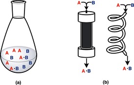
Batch method (a) and flow method (b).
As synthetic procedures, flow methods have several advantages over batch methods in terms of environmental compatibility, efficiency, and safety.3 However, in general synthesis by using flow methods is more difficult than by using batch methods. Indeed, it has generally been considered that synthesis by using flow methods can be applicable for the production of simple gasses but that it is difficult to apply to the synthesis of complex molecules such as APIs.4 Another aspect is more complicated purification methods of complex molecules than simple distillations that are encountered in petrochemical industry.
2. Modern Organic Synthesis and Organic Synthesis by Flow Methods
Modern organic synthesis is used for the synthesis of a wide range of useful compounds, and many synthetic reactions can be used to achieve high yields and high selectivities. Although the phrase “fine organic synthesis”5 is used occasionally, the word “fine” is often omitted because modern organic synthesis has developed to the stage that only reactions that proceed with high levels of control and efficiency are used routinely. On the other hand, according to classifications of synthetic methods, conventional organic syntheses involve almost exclusively batch methods, and the term “modern organic synthesis” is actually an abbreviation of “organic synthesis by batch methods.”6 Again, because “by batch methods” is self‐evident, it is typically not necessary to include the clarification.
However, syntheses and reactions that attain high yields and high selectivities by using flow methods have also been increasingly reported.7 These methods are properly classified as organic synthesis, however, as mentioned above, because modern organic synthesis is “organic synthesis by batch methods,” it seems inappropriate to call these methods simply organic synthesis. It may be termed “organic synthesis by flow methods;” however, at this moment, the quality and quantity of organic synthesis may be different between “organic synthesis by batch methods” and “organic synthesis by flow methods.” Therefore, instead of “organic synthesis by flow methods” we may use the term “flow fine synthesis,” which is “fine organic synthesis by flow methods,” wherein “fine” is the goal of flow synthesis (Figure 2).8
Figure 2.

Conventional organic synthesis and flow “fine” synthesis.
3. Flow “Fine” Synthesis and its Characteristics
Flow “fine” synthesis should be “reactions and synthesis that attain high yields and high selectivities by a flow method.” Furthermore, because a characteristic of the flow method is that it is continuous, flow “fine” synthesis should construct multistep flow systems9 by combining individual flow reactions to synthesize structurally complex molecules (Figure 3).
Figure 3.

Characteristics of flow “fine” synthesis.
Flow “fine” synthesis has several advantages over conventional organic synthesis. (1) High energy productivity and energy saving compared with batch methods can be realized. (2) The compact nature of a reactor means that space saving can be realized in addition to energy saving. (3) The low‐volume reaction space means that it is possible to suppress damage caused in the event of leakage even when high‐risk substances are used; therefore, flow “fine” synthesis ensures high safety. (4) It is possible to adjust the quantity of production by controlling the rate of introduction of starting materials; such “just‐in‐time”10 production can reduce the amount of waste generated, which can lead to lower costs. (5) Automation is easier, and it is possible to minimize the exposure of operators to hazardous chemicals. (6) As discussed below, by using columns packed with suitable catalysts, the separation of catalyst from the product is not required.
4. Types of Reactions of Flow “Fine” Synthesis
Reactions of flow “fine” synthesis can be divided into types I–IV (Figure 4).11
Figure 4.
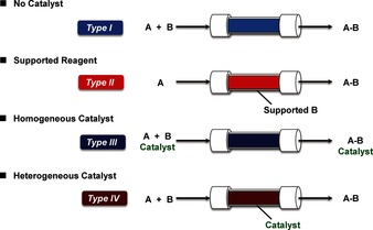
Classification of reactions for flow “fine” synthesis.11
Type I: Substrates (A and B) are passed through a column or hollow loop, etc. during which reactions occur. Although the product is obtained continuously, unreacted A or B or any by‐product(s) are also eluted as contaminants.
Type II: One of the substrates (B) is supported in a column. If an excess amount of B is used, the second substrate (A) is consumed. Although contamination of the product by unreacted A or B may be avoided, overreaction(s) may occur. In addition, once supported B is consumed, the column must be changed.
Type III: Substrate A reacts with B in the presence of a homogeneous catalyst. Although catalysis proceeds smoothly, the catalyst cannot be easily separated and it elutes as a contaminant in the product.
Type IV: Substrate A reacts with B in the presence of a heterogeneous catalyst. If catalysis proceeds smoothly, no separation of the catalyst from the product is required.
Based on the recent regulations on green sustainable chemistry,12 synthesis with catalysts is preferred to synthesis without catalysts because the latter can lead to energy saving and waste reduction. From this point, flow systems of types III and IV are recommended.13 Furthermore, whereas the products are contaminated by catalysts in type III flow systems, no contamination of catalysts is expected under ideal conditions in type IV systems. Therefore, type IV flow systems may have some advantages over other types of flow reactions.
5. Actual Flow “Fine” Synthesis: Synthesis of Natural Products and Active Pharmaceutical Ingredients (APIs) by Multistep Flow Systems
Selected examples of flow “fine” synthesis for the preparation of natural products and APIs are described.
rac‐Oxomaritidine (2006)14
Rac‐Oxomaritidine (1) is a cytotoxic alkaloid of the Amaryllidaceae family of natural products.15 The multistep flow synthesis of 1 is shown in Figure 5. The starting materials, 4‐(2‐bromoethyl)phenol (2) and 3,4‐dimethoxybenzyl alcohol (4), are both commercially available. In the first step, 2 was converted into the corresponding azide 3 quantitatively by using an immobilized azide exchange resin. The newly generated alkyl azide 3 was then treated with a polymer‐supported phosphine, furnishing the corresponding aza‐ylide, which was trapped on the supported material. In a separate line, 4 was oxidized to afford the aldehyde coupling partner 5 by using a prepacked column of tetra‐N‐alkylammonium perruthenate.16 The aldehyde was then passed through the column containing the immobilized aza‐ylide, producing the desired imine 6. The latter imine was then subjected to continuous‐flow hydrogenation using 10 % palladium on carbon to afford secondary amine 7. For the subsequent transformations, a solvent switch from tetrahydrofuran (THF) to dichloromethane (DCM) was required. After the solvent switch, secondary amine 7 and trifluoroacetic anhydride (TFAA, 5 equivalents) in DCM were passed onto a microfluidic reaction chip at 80 °C, which resulted in trifluoroacetylation of amine 7 to give amide 8. Although the temperature (80 °C) was above the usual boiling point of DCM, the system was controlled by using a backpressure regulator. The crude amide 8 was then passed through a short scavenging column containing a silica‐supported primary amine, which removed excess TFAA or residual trifluoroacetic acid (TFA). This reaction stream was then directed into a column containing polymer‐supported (ditrifluoroacetoxyiodo)benzene (PS‐PIFA),17 which led to oxidative phenolic coupling and to the generation of seven‐membered tricyclic intermediate 9. The resulting product was then passed directly into a column that contained a polymer‐supported base, which promoted cleavage of the amide bond, allowing 1,4‐conjugate addition to take place spontaneously, generating the target compound 1.
Figure 5.
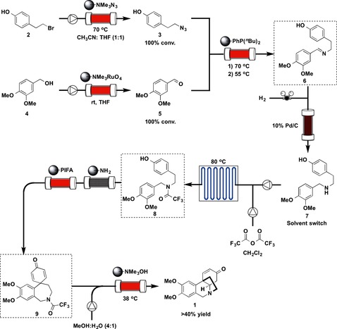
Flow synthesis of rac‐oxomaritidine (1).
Six columns and one microfluidic chip (microchannel) were used for the synthesis, and the seven‐step synthesis resulted in more than 40 % overall yield; pure 1 (20 mg) was obtained after separation by preparative HPLC.
The types of flow reactions used were Type I: 1; Type II: 5; Type III: 0; and Type IV: 1.
The synthesis described above, which was reported in 2006, is an outstanding piece of work that was developed at an early stage of flow “fine” synthesis.18 The synthesis was completed without the need for column chromatography or the use of aqueous work‐ups at any stage. The natural product was synthesized in an automated sequence from readily available starting materials in less than a day. Some four days were needed for the synthesis of 1 by using a batch method.19
N,N‐Diethyl‐4‐(3‐fluorophenylpiperidin‐4‐ylidenemethyl)benzamide (δ‐Opioid Receptor Agonist) (2010)20
N,N‐Diethyl‐4‐(3‐fluorophenylpiperidin‐4‐ylidenemethyl)benzamide (10) is a potent δ‐opioid receptor agonist that was developed by AstraZeneca.21 The four‐step flow synthesis of 10 is shown in Figure 6. A solution of iPrMgCl⋅LiCl in THF and a mixture of 1,3‐dimethyl‐3,4,5,6‐tetrahydro‐2(1 H)‐pyrimidinone (DMPU), diethylamine, and ester 11 in THF were combined, and the resulting mixture was passed through a convection flow coil (CFC) reactor (10 mL, 25 °C) before being merged with a third flow of 1‐Boc‐4‐piperidone (12). The reaction stream was then directed through a second CFC (10 mL, 25 °C), followed by three scavenger columns containing, in order, supported‐sulfonic acid, supported‐TsNHNH2, and silica gel to give tertiary alcohol 13. The supported‐sulfonic acid scavenged the residual amine starting material and the base, and the supported‐TsNHNH2 removed all the remaining piperidone 12; the silica gel column trapped the magnesium salts generated during the process. The exiting flow then entered into a ReactIR flow cell, and as soon as the indicative fingerprint signal of 13 was detected (i.e., IR stretching frequency 1690–1700 cm−1), the fourth input stream was started, allowing the Burgess reagent (14) to join the main reaction stream of 13. The reaction mixture was then pumped through a third CFC (10 mL, 60 °C) before entering into a column loaded with a mixture of supported‐sulfonic acid and supported benzylamine to sequester the excess Burgess reagent and associated by‐products, providing N‐Boc‐protected 15. Finally, a heated column (60 °C) of supported‐sulfonic acid was used to deprotect and catch the target molecule. Elution of the acidic column by using a solution of NH3 in MeOH completed the synthesis in a continuous fashion, and gave the product 10.
Figure 6.
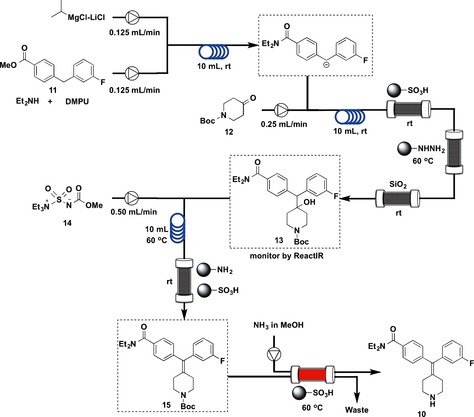
Flow synthesis of δ‐Opioid Receptor Agonist (10).
Four CFCs and one column were used, and the four‐step synthesis resulted in 35 % overall yield of pure 10 (74 mg).
The types of flow reactions used were: Type I: 3; Type II: 1; Type III: 0; Type IV: 0.
The chief characteristic of this synthesis is the combined use of type I flow reactions (Figure 4) and scavenger resins. The flow syntheses are carried out by using CFC reactors followed by scavenger resins, which removed unreacted starting materials, coproducts, and by‐products efficiently. The use of microreactors has advantages associated with mixing and heating but has suffered from problems of blocking, which was addressed by dilution of the reagents and through the judicious choice of solvents. The integrated purification employing solid‐supported reagents and in‐line IR analytical protocols using a newly developed ReactIR flow cell are remarkable.22
Artemisinin (2012, 2013)23, 24
Artemisinin (16) is a sesquiterpene endoperoxide that is highly effective against the protozoan parasite, Plasmodium falciparum, which is responsible for malaria.25 The semisynthesis of 16 was conducted by using a continuous‐flow method starting from dihydroartemisinic acid (DHAA, 17), which was derived from artemisinic acid by hydrogenation26 or produced by fermentation in engineered yeast.27 Artemisinic acid can be either extracted from the plant Artemisia annua (sweet wormwood) in high yields, or produced in engineered yeast.28
A continuous‐flow conversion of 17 into artemisinin (16) is outlined in Figure 7. The key challenge was developing a continuous photochemical transformation29 involving a singlet‐oxygen‐induced ene reaction of 17 to afford tertiary allylic hydroperoxide 18,30 acid‐mediated cleavage of the oxygen–oxygen bond (Hock cleavage) of 18 to provide 19,31 and oxidation of 19 with triplet oxygen to form 20 and finally 16.32
Figure 7.
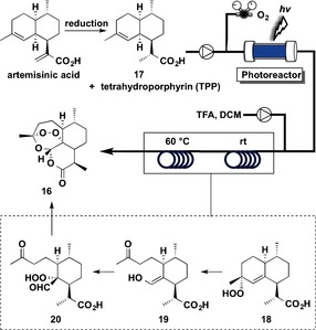
Flow synthesis of artemisinin (16).
A single, fully integrated continuous‐flow synthesis to convert 17 into 16 required a reactor that receives as input, 17, oxygen gas, and tetraphenylporphyrin (TPP) as photosensitizer. For this purpose, a commercially available continuous‐flow system that included HPLC pumps was combined with an in‐house photochemical flow setup, as well as an additional mixer and thermal reactor.23 In this reactor, a solution of 17 and the photosensitizer TPP in DCM were mixed at a flow rate of 2.5 mL min−1 with a stream of oxygen gas (7.5 mL min−1), and the solution was passed through the photoreactor. The residence time in the reactor was approximately 2 min. By using an acid‐resistant pump, a solution of TFA in DCM was added at a flow rate of 0.5 mL min−1 to the outlet stream of the photoreactor, which contained mainly 18, to induce the acid‐catalyzed Hock cleavage. The acid was added just after the completion of the singlet‐oxygen reaction.
Hock cleavage took place in a PTFE reactor (26 mL volume total, with 16 mL maintained at room temperature and 10 mL heated at 60 °C). A residence time of approximately 2.5 min was required for the Hock cleavage (from 18 to 19), oxidation with triplet oxygen (from 19 to 20), and further condensation (from 20 to 16). After a total residence time of 4.5 min, a product flow that was comprised mainly of 16, was obtained. Purification by chromatography gave 16 in 39 % yield from DHAA (17).
Three flow coil reactors were used, and the four‐step synthesis resulted in 39 % overall yield of pure 15 (1.36 g). The total residence time was 4.5 min.
The types of flow reactions used were: Type I: 1; Type II: 0; Type III: 2; Type IV: 0.
The synthesis was subsequently improved for large‐scale preparation.24 To attain maximum yield and efficiency, dicyanoanthracene (DCA) was used in place of TPP as photosensitizer, and toluene was selected as solvent. DHH (17), DCA, TFA, and O2 were flowed into the photoreactor, which was cooled at −20 °C. After passing through the photoreactor, the solution was heated to 10 °C in a reaction line of 10 mL volume and a second reaction line of 30 mL volume at room temperature. Crude 16 was obtained in 65 % yield, which was purified to give a 48 % yield (16.08 g) of 15 in 11.5 min residence time.
The elegant setup of the flow reactors enabled very efficient control of the reaction, and demonstrated the clear advantages of the flow method over the batch method.
Neurolepticum Olanzapine (Zyprexa) (2013)33
Olanzapine (21) is one of the best‐selling drugs worldwide. It exerts antagonistic activity toward the dopamine receptor type 4 (D4 receptor) and the serotonin receptor type 2 (5HT2 receptor),34 and it is used for the treatment of bipolar disorder and schizophrenia.35 The multistep flow synthesis of 21 was established according to the synthetic route shown in Figure 8.
Figure 8.
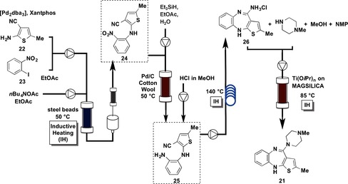
Flow synthesis of olanzapine (21).
The continuous, three‐step synthesis of thieno[1,5]benzodiazepine 26 was started from Pd‐catalyzed amination,36 of thiophene 22 and aryl iodide 23. A solution of 22, 23, Pd2(dba)3, Xantphos, and nBu4NOAc in ethyl acetate was flowed into a reactor filled with steel beads at 50 °C (high‐frequency inductive heating,37 was used). The reaction stream moved to an in‐line extraction, followed by passage through a cartridge filled with silica to remove traces of Pd. Other materials such as Al2O3 and sulfur were less effective. Subsequent reduction of the nitro group was conducted by flowing a solution of 24 and Et3SiH in ethyl acetate through a column packed with Pd/C and cotton wool.38 The reaction mixture containing aromatic amine 25, after reduction of the nitro group, was collected in a glass vessel, where remaining hydrogen gas was liberated, allowing for constant flow rates. At this point, a stream of HCl in MeOH (0.6 m) was added and the solution of 25 was injected into a tubular reactor at 140 °C with high‐frequency inductive heating to afford thieno[1,5]benzodiazepine 26. It was possible to conduct the three steps continuously for 30 h without chromatographic purification to obtain 313 mg (88 % yield) of 26. Notably, the overall reactor volume was approximately 8 mL for all three steps and no solvent switch was conducted. The formation of olanzapine (21) was achieved with an additional reactor (3 mL volume), which contained a silica‐supported titanium Lewis acid, to promote the substitution reaction at 85 °C with high‐frequency inductive heating. Olanzapine (21) was obtained in 83 % yield (293 mg). The patent describes a productivity of 1.88 mmol/LR⋅h (LR=reaction volume in liters) in a discontinuous batch system, whereas this flow method has a productivity of 3.97 mmol/LR⋅h.
The synthesis of olanzapine (21) was conducted in a four‐step flow “fine” synthesis in 88 % yield in the first three steps and in 83 % yield in the fourth step. Compound 21 was obtained in a total amount of 293 mg in 15 h. Three column reactors and one loop reactor were employed.
The types of flow reactions used were: Type I: 1, Type II: 0, Type III: 1, Type IV: 2.
One of the key technologies for this synthesis is the advanced heating system.37 The rapid heating of reactants inside the flow device is an important issue when syntheses are conducted in mesofluidic reactors at high flow rates. The elegant heating technology was used in three flow systems in the synthesis.
Ibuprofen (2009, 2015)39, 40
Ibuprofen (27) is a high‐volume, nonsteroidal anti‐inflammatory drug (NSAID). Two continuous‐flow syntheses of 27 have been reported: the first example, reported in 2009,38 is a fundamental, laboratory‐scale synthesis; the second, reported in 2015,40 is a scale‐up synthesis including chemical engineering technologies.
The first three‐step, continuous‐flow synthesis of 27 was conducted using a simplified microreactor that eliminated the need for purification and isolation steps. To achieve this continuous‐flow synthesis, a careful retrosynthetic analysis of 27 was performed. Reactions therefore had to be designed such that by‐products and excess reagents from one reaction were compatible with downstream reactions. The general three‐step synthesis of 27 is outlined in Figure 9.
Figure 9.
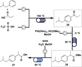
Flow synthesis of ibuprofen (27); Part 1.
The first step was Friedel–Crafts acylation,41 for which mixing isobutylbenzene (IBB) and propionic acid with triflic acid (TfOH) proved to be an effective method to synthesize 28.42 It is considered that the reaction of ThOH with propionic acid leads to the formation of a protonated mixed anhydride, which is a very reactive acylation reagent. This TfOH/propionic acid system was not only effective with the first step but was also compatible with the second step. To run acylation experiments under continuous‐flow conditions, a solution of IBB and propionic acid was mixed with a stream of TfOH, resulting in plug flow. Heating the reactor at 150 °C for 5 min gave the highest conversion and yield. The next step was the 1,2‐aryl migration.43 An efficient mixing of the outlet stream from the first step with the PhI(OAc)2/trimethyl orthoformate (TMOF) reagent stream for the second step was conducted at 0 °C. It was necessary to cool here due to significant off‐gassing that occurred when the mixing was conducted at room temperature. In this system, no additional acid was required, because the TfOH from the Friedel–Crafts acylation also facilitated the 1,2‐aryl migration. The mixture was heated at 50 °C and the residence time was 2 min. The final step was achieved by saponification of methyl ester 29 with KOH. The outlet stream from the second step was combined with a stream of 5 m KOH and heated at 65 °C for 3 min. The excellent heat transfer of the microreactor allowed the acidic stream to be mixed with the basic stream without danger from the exotherm. Sampling the outlet stream showed only the presence of residual IBB, iodobenzene, and trace amounts of methyl ester 29. After acidic work‐up, ibuprofen (27) was obtained in 68 % crude yield and 51 % yield after recrystallization.
Three coil reactors were used in this synthesis, and the total residence time was 10 min. Ibuprofen (27) was obtained at 9 mg min−1 with an overall yield of 51 %.
The types of flow reactions used were: Type I: 1, Type II: 0; Type III: 2, Type IV: 0.
This laboratory‐scale, continuous‐flow synthesis was subsequently applied to large‐scale production.40 The basic synthetic scheme was the same, but several improvements were undertaken to achieve higher throughput (Figure 10). The Friedel–Crafts acylation was conducted using AlCl3,41 and the starting material was not a carboxylic acid but an acid chloride. The reaction proceeded under neat conditions, and it was possible to conduct an exothermic in‐line quench of high concentrations of precipitation‐prone AlCl3 as well as liquid–liquid separations, which were run to provide solvent‐free product 28. The second step was carried out by using iodine monochloride (ICl).44 Highly corrosive ICl was pumped neat for several hours without pump failure, enabling very rapid formation of methyl ester 29 in the oxidative 1,2‐aryl rearrangement. Final ester hydrolysis was conducted by using NaOH.
Figure 10.
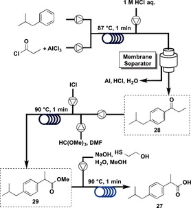
Flow synthesis of ibuprofen (27): Part 2.
In a total residence time of 3 min, ibuprofen (27) was assembled from its elementary building blocks with an average yield of more than 90 % for each step. A scale‐up of this five‐stage process (three bond‐forming steps, one work‐up, and one in‐line liquid–liquid separation) provided 27 at a rate of 8.09 g h−1 using a system with an overall footprint of half the size of a standard laboratory fume hood.
Three coil reactors were used in this synthesis, and the total residence time was 3 min. Ibuprofen was obtained at 8.09 g h−1 with an overall yield of 83 %. The types of flow reactions used were: Type I: 1, Type II: 0; Type III: 2, Type IV: 0.
In multistep continuous synthesis, by‐products, excess reagents, and promoters or catalysts from one reaction have to be compatible with downstream reactions. In this context, the first synthesis is well designed based on modern organic synthesis. The first Friedel–Crafts acylation is conducted using a carboxylic acid as the starting material.45 Most Friedel–Crafts acylation reactions are conducted with acid chlorides or acid anhydrides as the starting materials. The first reaction has some advantages over the conventional reaction, because acid chlorides or acid anhydrides are usually prepared from carboxylic acids. Only water forms in the first reaction, whereas HCl or a carboxylic acid is generated in the second reaction. Moreover, in the first synthesis, TfOH promotes the Friedel–Crafts acylation and it also mediates 1,2‐aryl migration in the second step. On the other hand, in the second synthesis, the use of very reactive reagents AlCl3 and ICl makes it possible to promote rapid reactions; although these reagents or their decomposition compounds often influence other reactions, in this system they are successfully quenched before the next steps. These considerations clearly demonstrate the excellent contrasting approaches to such syntheses.
(R)‐Rolipram (2015)11
The anti‐inflammatory drug rolipram (28) is a member of the γ‐aminobutyric acid (GABA) family;46 it is a selective phosphodiesterase 4 (PDE4) inhibitor that is particularly effective for the PDE4B subtype of PDE4.47, 48, 49 Moreover, rolipram is known as a possible antidepressant and has been reported to have anti‐inflammatory, immunosuppressive, and antitumor effects.47, 48 Rolipram has also been proposed as a treatment for multiple sclerosis, and has been suggested to have antipsychotic effects.50 Furthermore, it has been reported that (R)‐rolipram has anti‐inflammatory activity, whereas (S)‐rolipram does not.49
Both (R)‐ and (S)‐rolipram were selected as targets for continuous‐flow synthesis not only because rolipram itself is a very interesting and promising drug for several targets, as noted above, but also because the completed flow synthesis may be applicable to the synthesis of other GABA derivatives. The synthesis of (R)‐ and (S)‐rolipram was planned from commercially available starting materials using continuous‐flow systems (Figure 11). The key characteristic here is that only type IV reactions (Figure 4) are used in this synthesis. Commercially available aldehyde 29 and nitromethane 30 are converted into nitroalkene 31. Catalytic asymmetric 1,4‐addition of malonate 32 to 31 affords enantiomerically enriched γ‐nitro ester 33. The nitro group of 33 is reduced selectively to afford γ‐lactam 34 after cyclization. Finally, the ester group of 34 is removed to afford 28.
Figure 11.
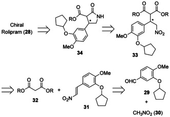
Retrosynthesis of rolipram (28) by a flow method.
First, the flow synthesis of 31 from 29 and 30 by using a heterogeneous catalyst was examined (Figure 12).51 Toluene was selected as a solvent because the following step, the asymmetric 1,4‐addition, proceeded smoothly in toluene. It was found that a silica‐supported amine with anhydrous calcium chloride gave a high yield of 31 when almost equimolar amounts of 29 and 30 were applied at 75 °C. The solution of 29 and 30 in toluene was introduced from the bottom of the column, and the desired product 31 was obtained in more than 90 % yield. The system was found to be stable for at least one week. The asymmetric 1,4‐addition of malonate 32 to 31 by using a chiral heterogeneous catalyst was then examined. Catalytic asymmetric reactions provide one of the most efficient routes to enantiomerically enriched products.52 A column was filled with a supported calcium catalyst (PS‐(S)‐Pybox‐calcium chloride).53 A stream of nitroalkene 31 synthesized in the first column and a solution of malonate 32 and triethylamine in toluene was mixed and introduced into the column. It was found that when the reaction was conducted at 0 °C, the desired γ‐nitro ester 33 was obtained in high yield and with high enantioselectivity. Under the optimized conditions, the mixture of the stream from the first column and 32 was precooled at 0 °C by using a loop, and the second column was separated into two columns. The crude product solution in receiver 2 was collected. It was confirmed to contain mainly 33, with small amounts of 30 and 32, and triethylamine.
Figure 12.
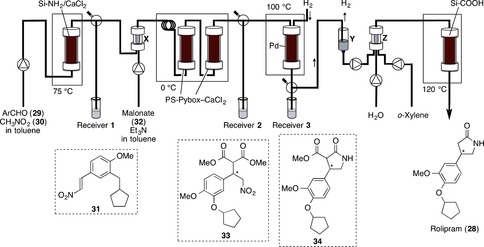
Flow synthesis of (R)‐ and (S)‐rolipram (28).
The next step involved the reduction of the nitro group of 33 to the corresponding amino group.54 Experimental conditions required the stream of the toluene solution obtained from the second column to be under atmospheric pressure. A newly developed polysilane‐supported palladium/carbon (Pd/PMPSi‐C) catalyst55 worked well for the reduction. The mixed solution (crude 33 in toluene) and hydrogen gas (3 mL min−1) were introduced into the column (filled with Pd/PMPSi‐C and Celite) at 100 °C by downflow. Under these conditions, the desired reduction proceeded smoothly to afford γ‐lactam 34. The final stage in the synthesis of rolipram (28) involved the hydrolysis and decarboxylation of the ester part of 34. It was found that the desired transformations proceeded in the presence of a silica‐supported carboxylic acid. Small columns of Amberlyst 15Dry (Y) and Celite (Z) were then added, and o‐xylene was introduced. The main stream from the previous column was combined with o‐xylene and water, and the total flow was passed through the column from the top down at 120 °C. Finally, (S)‐rolipram was obtained ((S)‐28, 50 % yield from 29 after preparative TLC, 997.8 mg 24 h−1, 96 % ee). The flow system was found to be stable for at least one week. Recrystallization from water/methanol gave optically pure (S)‐rolipram (>99 % ee). Direct recrystallization of the crude product afforded chemically and enantiomerically pure (S)‐rolipram without chromatography. The antipole (R)‐rolipram was also synthesized by continuous flow by simply replacing the second column packed with PS‐(S)‐Pybox‐calcium chloride with another column bearing PS‐(R)‐Pybox‐calcium chloride (the opposite enantiomer). The procedure remained the same and similar productivity was obtained ((R)‐1, 50 % yield from 2, 96 % ee).
Thus, the synthesis of (R)‐ and (S)‐rolipram was completed. Commercially available starting materials were successively passed through the columns containing heterogeneous achiral and chiral catalysts to directly afford the drug with high enantioselectivity. Eight chemical transformation steps were conducted smoothly during the flow, without isolation of any intermediates and without the separation of any catalysts, coproducts, by‐products, or excess reagents. In the flow system, each step can be monitored by using receivers (real‐time analysis is possible). It is noteworthy that all four columns employed are of the desirable type IV flow system, and that the product does not contain any metal (palladium, <0.01 ppm), as confirmed by inductively coupled plasma analysis. Moreover, this is the first example of the successful use of a chiral catalyst in multistep continuous‐flow synthesis of drugs or biologically important compounds.
Four column reactors were employed in the four‐step synthesis. (R)‐ or (S)‐Rolipram (28) was obtained in 50 % yield, and a total amount of 1 g was obtained in 24 h.
The types of flow reactions used were: Type I: 0, Type II: 0, Type III: 0, Type IV: 4.
The present multistep continuous‐flow synthesis has been developed for use on the laboratory scale, and the drugs were obtained on a gram‐scale. It has been confirmed that the system is stable and that the flow continues at steady state during the synthesis. Indeed, the system is stable for at least one week, and the same yields and enantioselectivities are obtained for the syntheses of (R)‐ and (S)‐rolipram. Furthermore, it has also been confirmed that heterogeneous catalysts used in this flow system are robust, air stable, and have a long lifetime. For example, the chiral calcium catalyst can be used for more than several months without loss of any catalytic activity or enantioselectivity.
6. Conclusions and Perspectives
The concept of flow “fine” synthesis and some examples of its use for the flow “fine” synthesis of natural products and APIs have been described.56 The future direction of flow “fine” synthesis has much in common with that of modern synthetic organic chemistry. Similar to the development of synthetic organic chemistry, which has been pursuing “efficiency” in many ways, the first objective of flow “fine” synthesis is also to improve efficiency. In synthetic organic chemistry, it goes without saying that higher yields are desired. However, in flow “fine” synthesis, even if the product is obtained in high yield, reactions that produce a coproduct, such as the Wittig reaction,57 are not suitable. When used in multistep flow synthesis, the flow of the coproduct downstream is not desirable. However, reactions such as the Wittig reaction are also not necessarily ideal from the viewpoint of atom economy,58 and improved approaches in this area are increasingly demanded in synthetic organic chemistry.59 While we encourage the use of immobilized and solid catalysts in flow “fine” synthesis,60 the use of a catalyst is also encouraged in synthetic organic chemistry from the point of view of green chemistry;12 there is clearly also a common point in this respect.
In addition, it is clear that organic synthesis by flow methods is not limited to reactions that cannot be conducted in a batch method.61 Flow reactions have been developed that produce products that can also be synthesized in a batch method. This is because flow methods have a number of methodological advantages compared with batch methods, as noted previously. Currently, very few organic reactions by flow methods are available compared with the overwhelming number of batch reactions that can be used; however, such flow reactions are under development. A sufficient number of organic reactions by flow methods will become available and flow methods will be developed further to realize high yields and high selectivities in the future. At present, because almost all organic reactions are carried out by using batch methods, it is not necessary to specify organic synthesis “by a batch method.” However, if organic synthesis by flow methods becomes more commonplace, it may become necessary to specify whether a synthesis has been conducted by “a batch method” or “a flow method” in the future.
Finally, the ripple effects and future prospects of flow “fine” synthesis are discussed. Herein, examples of the synthesis of natural products and APIs by flow “fine” synthesis have been demonstrated. Similarly, a range of other APIs as well as other fine chemicals including flavors, agrochemicals, electronic materials, etc. are expected to be synthesized by using similar flow methods in the future. A key feature of a flow method compared with a batch method is that the former approach can be used to prepare compounds on demand from small scale to large scale, which enables fine chemicals to be produced on a just‐in‐time basis. If, for example, the flow total synthesis of anti‐influenza drugs could be achieved, the stockpiling of such drugs that is currently necessary,62 may no longer be required. This example may suffice to demonstrate the significance of the study of organic synthesis by flow methods.
It is important to approach the study of organic synthesis by flow methods from the perspective of both basic research and applied research. In basic research, the development of catalysts for organic synthesis by flow methods, in particular the development of heterogeneous catalysts and chiral catalysts, is crucial, as is the development of reactions for organic synthesis by flow methods. Moreover, synthetic plans and retrosynthetic analyses for organic synthesis by flow methods, and research into continuous‐flow synthesis of fine chemicals including APIs based on them, are also essential. Basic research in these areas will allow a new chapter in conventional organic chemistry and synthetic organic chemistry to be started.
With respect to applied research, which is beyond the scope of this article, one of the features of organic synthesis by flow methods is that the distance between basic research and applied research is not great. Successful flow synthesis on a several‐gram scale system developed as a result of basic research in a university may be readily applicable to actual fine chemical manufacturing by simply increasing the scale.
Due to methodological excellence, flow methods are leading candidates for the next generation of manufacturing methods that can mitigate environmental concerns. In particular, regarding pharmaceutical manufacturing, the prediction made by the FDA in 2011—“it is predicted that manufacturing will change in the next 25 years as current manufacturing practices are abandoned in favor of cleaner, flexible, more efficient continuous manufacturing”63—will become a powerful tail wind that is expected to drive the development of organic synthesis by flow methods.
Biographical Information
Professor Shū Kobayashi received his Ph.D. at the University of Tokyo in 1988 (T. Mukaiyama). Following an initial period as assistant professor (in 1987), he was promoted to lecturer (in 1991) then associate professor (in 1992) at Science University of Tokyo (Tokyo Science University). In 1998, he moved to the Graduate School of Pharmaceutical Sciences, the University of Tokyo, as full professor. In 2007, he was appointed to his current position as professor of Organic Chemistry in the Department of Chemistry, Faculty of Science, the University of Tokyo. He has held visiting professorships, including the Universite Louis Pasteur, Strasbourg (1993), Kyoto University (1995), Nijmegen University (1996), Philipps‐University of Marburg (1997), Paris‐Sud (2010). Professor Kobayashi has wide‐ranging research interests that include the development of new synthetic methods and novel catalysts, organic reactions in water, solid‐phase synthesis, total synthesis of biologically interesting compounds, and organometallic chemistry. He has held numerous named lectureships and is a recipient of many prestigious awards, including the Chemical Society of Japan Award for Young Chemists (1991), Springer Award in Organometallic Chemistry (OMCOS Award) (1997), IBM Science Award (2001), Organic Reactions Lecturer (2002), Nagoya Silver Medal (2002), Mitsui Chemical Catalysis Science Award (2005), JSPS Prize (2005), the Arthur C. Cope Scholar Award from the American Chemical Society (2006), Howard Memorial Lecturer (2006), C.S. Hamilton Award (2007), Merck‐Cambridge Lecturer (2007), Humboldt Research Award (2013), and Green Chemistry Minister of Education Award (2013).

Acknowledgements
Our work written in this article was partially supported by a Grant‐in‐Aid for Science Research from the Japan Society for the Promotion of Science (JSPS), the Global COE Program, the University of Tokyo, the Japan Science and Technology Agency (JST), and the Ministry of Education, Culture, Sports, Science and Technology (MEXT, Japan). I would also like to thank all my co‐workers whose names are cited in References for their great contributions.
S. Kobayashi, Chem. Asian J. 2016, 11, 425.
References
- 1. Appl M., Ammonia in Ullmann's Encyclopedia of Industrial Chemistry, Wiley-VCH, Weinheim, 2006. [Google Scholar]
- 2.
- 2a. Geyer K., Codée J. D. C., Seeberger P. H., Chem. Eur. J. 2006, 12, 8434–8442; [DOI] [PubMed] [Google Scholar]
- 2b. Mason B. P., Price K. E., Steinbacher J. L., Bogdan A. R., McQuade D. T., Chem. Rev. 2007, 107, 2300–2318; [DOI] [PubMed] [Google Scholar]
- 2c. Yoshida J., Chem. Rec. 2010, 10, 332–341; [DOI] [PubMed] [Google Scholar]
- 2d. Yoshida J., Kim H., Nagaki A., ChemSusChem 2011, 4, 331–340; [DOI] [PubMed] [Google Scholar]
- 2e. Microreactors in Organic Chemistry and Catalysis (Ed.: T. Wirth), Wiley-VCH, Weinheim, 2013. [Google Scholar]
- 3.
- 3a. Ley S. V., Baxendale I. R., Nat. Rev. Drug Discovery 2002, 1, 573–586; [DOI] [PubMed] [Google Scholar]
- 3b. Wegner J., Ceylan S., Kirschning A., Chem. Commun. 2011, 47, 4583–4592; [DOI] [PubMed] [Google Scholar]
- 3c. Hartman R. L., McMullen J. P., Jensen K. F., Angew. Chem. Int. Ed. 2011, 50, 7502–7519; [DOI] [PubMed] [Google Scholar]; Angew. Chem. 2011, 123, 7642–7661; [Google Scholar]
- 3d. Wiles C., Watts P., Green Chem. 2012, 14, 38–54. [Google Scholar]
- 4.
- 4a. Poechlauer P., Manley J., Broxterman R., Gregertsen B., Ridemark M., Org. Process Res. Dev. 2012, 16, 1586–1590; [Google Scholar]
- 4b. Malet-Sanz L., Susanne F., J. Med. Chem. 2012, 55, 4062–4098; [DOI] [PubMed] [Google Scholar]
- 4c. Van Arnum P., Pharm. Technol. 2013, 37, 78–82; [Google Scholar]
- 4d. Mascia S., Heider P. L., Zhang H., Lakerveld R., Benyahia B., Barton P. I., Braatz R. D., Cooney C. L., Evans J. M. B., Jamison T. F., Jensen K. F., Myerson A. S., Trout B. L., Angew. Chem. Int. Ed. 2013, 52, 12359–12363; [DOI] [PubMed] [Google Scholar]; Angew. Chem. 2013, 125, 12585–12589. [Google Scholar]
- 5.The phrase “fine organic synthesis” may not be very common as an English phrase but is often used as the corresponding Japanese; “Seimitu Yuuki Gousei,” where “Yuuki Gousei” is “Organic Synthesis” and “Seimitsu” is corresponding to “Fine.” The meaning is close to Stereoselective Synthesis or Modern Organic Synthesis.
- 6. Comprehensive Organic Synthesis, Vol. 9, Enabling Technologies for Organic Synthesis (Vol. Ed.: C. J. Welch; Eds.: P. Knochel, G. A. Molander), Elsevier, Amsterdam, 2014. [Google Scholar]
- 7.
- 7a. Wegner J., Ceylan S., Kirschning A., Adv. Synth. Catal. 2012, 354, 17–57; [Google Scholar]
- 7b. Pastre J. C., Browne D. L., Ley S. V., Chem. Soc. Rev. 2013, 42, 8849–8869; [DOI] [PubMed] [Google Scholar]
- 7c. McQuade D. T., Seeberger P., J. Org. Chem. 2013, 78, 6384–6389; [DOI] [PubMed] [Google Scholar]
- 7d. Baxendale I. R., Brocken L., Mallia C. J., Green Process Synth. 2013, 2, 211–230; [Google Scholar]
- 7e. Su Y., Straathof N. J. W., Hessel V., Noële T., Chem. Eur. J. 2014, 20, 10562–10589; [DOI] [PubMed] [Google Scholar]
- 7f. Gutmann B., Cantillo D., Kappe C. O., Angew. Chem. Int. Ed. 2015, 54, 6688–6729; [DOI] [PubMed] [Google Scholar]; Angew. Chem. 2015, 127, 6788–6832. [Google Scholar]
- 8.The corresponding Japanese of “flow fine synthesis” is also used in Japan, related to “fine organic synthesis.”[5]
- 9. Webb D., Jamison T. F., Chem. Sci. 2010, 1, 675–680. [Google Scholar]
- 10. Barkman W. E., In-Process Quality Control for Manufacturing, CRC Press, Boca Raton, 1989. [Google Scholar]
- 11. Tsubogo T., Oyamada H., Kobayashi S., Nature 2015, 520, 329–332. [DOI] [PubMed] [Google Scholar]
- 12.
- 12a. Anastas P. T., Warner J. C., Green Chemistry, Theory and Practice, Oxford University Press, Oxford, 1998; [Google Scholar]
- 12b. Sheldon R. A., Arends I. W. C. E., Hanefeld U., Green Chemistry and Catalysis, Wiley-VCH, Weinheim, 2007; [Google Scholar]
- 12c. Poliakoff M., Licence P., Nature 2007, 450, 810–812; [DOI] [PubMed] [Google Scholar]
- 12d. Clark J. H., Luque R., Matharu A. S., Annu. Rev. Chem. Biomol. Eng. 2012, 3, 183–207; [DOI] [PubMed] [Google Scholar]
- 12e. Green Chemistry: Fundamentals and Applications (Eds.: S. C. Ameta, R. Ameta), CRC Press, Boca Raton, 2013; See also, [Google Scholar]
- 12f. Ley S. V., Chem. Rec. 2012, 12, 378–390. [DOI] [PubMed] [Google Scholar]
- 13.
- 13a. Kirschning A., Solodenko W., Mennecke K., Chem. Eur. J. 2006, 12, 5972–5990; [DOI] [PubMed] [Google Scholar]
- 13b. Frost C. G., Mutton L., Green Chem. 2010, 12, 1687–1703; [Google Scholar]
- 13c. Hintermair U., Francio G., Leitner W., Chem. Commun. 2011, 47, 3691–3701; [DOI] [PubMed] [Google Scholar]
- 13d. Tsubogo T., Ishiwata T., Kobayashi S., Angew. Chem. Int. Ed. 2013, 52, 6590–6604; [DOI] [PubMed] [Google Scholar]; Angew. Chem. 2013, 125, 6722–6737; [Google Scholar]
- 13e. Puglisi A., Benaglia M., Chiroli Valerio, Green Chem. 2013, 15, 1790–1813; [Google Scholar]
- 13f. Rodríguez-Escrich C., Pericàs M. A., Eur. J. Org. Chem. 2015, 1173–1188; [Google Scholar]
- 13g. Atodiresei I., Vila C., Rueping M., ACS Catal. 2015, 5, 1972–1985; [Google Scholar]
- 13h. Finelli F. G., Mirandab L. S. M., de Souza R. O. M. A., Chem. Commun. 2015, 51, 3708–3722; [DOI] [PubMed] [Google Scholar]
- 13i. Vural Gürsel I., Noël T., Wang Q., Hessel V., Green Chem. 2015, 17, 2012–2026. [Google Scholar]
- 14. Baxendale I. R., Deeley J., Griffiths-Jones C. M., Ley S. V., Saaby S., Tranmer G. K., Chem. Commun. 2006, 2566–2568. [DOI] [PubMed] [Google Scholar]
- 15. Jin Z., Li Z., Huang R., Nat. Prod. Rep. 2002, 19, 454–476. [DOI] [PubMed] [Google Scholar]
- 16.
- 16a. Hinzen B., Ley S. V., J. Chem. Soc. Perkin Trans. 1 1997, 1907–1908; [Google Scholar]
- 16b. Lenz R., Ley S. V., J. Chem. Soc. Perkin Trans. 1 1997, 3291–3292; [Google Scholar]
- 16c. Hinzen B., Lenz R., Ley S. V., Synthesis 1998, 977–979. [Google Scholar]
- 17.
- 17a. Ley S. V., Thomas A. W., Finch H., J. Chem. Soc. Perkin Trans. 1 1999, 669–672; [Google Scholar]
- 17b. Togo H., Nogami G., Yokoyama M., Synlett 1998, 534–536. [Google Scholar]
- 18. Baxendale I. R., Griffiths-Jones C. M., Ley S. V., Tranmer G. K., Synlett 2006, 427–430. [Google Scholar]
- 19. Ley S. V., Schucht O., Thomas A. W., Murray P. J., J. Chem. Soc. Perkin Trans. 1 1999, 1251–1252. [Google Scholar]
- 20. Qian Z., Baxendale I. R., Ley S. V., Chem. Eur. J. 2010, 16, 12342–12348. [DOI] [PubMed] [Google Scholar]
- 21. Wei Z. Y., Brown W., Takasaki B., Plobeck N., Delorme D., Zhou F., Yang H., Jones P., Gawell L., Gagnon H., Schmidt R., Yue S. Y., Walpole C., Payza K., St-Onge S., Labarre M., Godbout C., Jakob A., Butterworth J., Kamassah A., Morin P. E., Projean D., Ducharme J., Roberts E., J. Med. Chem. 2000, 43, 3895–3905. [DOI] [PubMed] [Google Scholar]
- 22.
- 22a. Carter C. F., Baxendale I. R., O'Brien M., Pavey J. B. J., Ley S. V., Org. Biomol. Chem. 2009, 7, 4594–4597; [DOI] [PubMed] [Google Scholar]
- 22b. Carter C. F., Lange H., Ley S. V., Baxendale I. R., Wittkamp B., Goode J. G., Gaunt N. L., Org. Process Res. Dev. 2010, 14, 393–404. [Google Scholar]
- 23. Lévesque F., Seeberger P. H., Angew. Chem. Int. Ed. 2012, 51, 1706–1709; [DOI] [PubMed] [Google Scholar]; Angew. Chem. 2012, 124, 1738–1741. [Google Scholar]
- 24. Kopetzki D., Lévesque F., Seeberger P. H., Chem. Eur. J. 2013, 19, 5450–5456. [DOI] [PubMed] [Google Scholar]
- 25.World Health Organization. World Malaria Report 2010 (WHO, Geneva, 2010).
- 26. Kraft V., Kretzschmar G., Rossen K., WO 2011/030223A2, 2011.
- 27. Zhang Y., Teoh K. H., Reed D. W., Maes L., Goossens A., Olson D. J. H., Ross A. R. S., Covello P. S., J. Biol. Chem. 2008, 283, 21501–21508. [DOI] [PubMed] [Google Scholar]
- 28. Ro D. K., Paradise E. M., Ouellet M., Fisher K. J., Newman K. L., Ndungu J. M., Ho K. A., Eachus R. A., Ham T. S., Kirby J., Chang M. C. Y., Withers S. T., Shiba Y., Sarpong R., Keasling J. D., Nature 2006, 440, 940–943. [DOI] [PubMed] [Google Scholar]
- 29.
- 29a. Hook B. D. A., Dohle W., Hirst P. R., Pickworth M., Berry M. B., Booker-Milburn K. I., J. Org. Chem. 2005, 70, 7558–7564; [DOI] [PubMed] [Google Scholar]
- 29b. Lévesque F., Seeberger P. H., Org. Lett. 2011, 13, 5008–5011. [DOI] [PubMed] [Google Scholar]
- 30.
- 30a. Schweitzer C., Schmidt R., Chem. Rev. 2003, 103, 1685–1758; [DOI] [PubMed] [Google Scholar]
- 30b. Hoffmann N., Chem. Rev. 2008, 108, 1052–1103. [DOI] [PubMed] [Google Scholar]
- 31.
- 31a. Lange J.-P., Breed A. J. M., Catal. Commun. 2002, 3, 25–28; [Google Scholar]
- 31b. Olah G. A., Parker D. G., Yoneda N., Angew. Chem. Int. Ed. Engl. 1978, 17, 909–931; [Google Scholar]; Angew. Chem. 1978, 90, 962–984; [Google Scholar]
- 31c. Brinkhorst J., Nara S. J., Pratt D. A., J. Am. Chem. Soc. 2008, 130, 12224–12225; [DOI] [PubMed] [Google Scholar]
- 31d. Frimer A. A., Chem. Rev. 1979, 79, 359–387. [Google Scholar]
- 32. Chen B.-C., Zhou P., Davis F. A., Ciganek E., Org. React. 2004, 64, 1–356. [Google Scholar]
- 33. Hartwig J., Ceylan S., Kupracz L., Coutable L., Kirschning A., Angew. Chem. Int. Ed. 2013, 52, 9813–9817; [DOI] [PubMed] [Google Scholar]; Angew. Chem. 2013, 125, 9995–9999. [Google Scholar]
- 34.
- 34a. Gerlach J., Peacock L., Int. Clin. Psychopharmacol. 1995, 10, 39–48; [DOI] [PubMed] [Google Scholar]
- 34b. Reynolds G. P., J. Psychopharmacol. 2004, 18, 340–345. [DOI] [PubMed] [Google Scholar]
- 35. Bhana N., Foster R. H., Olney R., Plosker G. L., Drugs 2001, 61, 111–161. [DOI] [PubMed] [Google Scholar]
- 36.
- 36a. Paul F., Patt J., Hartwig J. F., J. Am. Chem. Soc. 1994, 116, 5969; [Google Scholar]
- 36b. Guram A. S., Buchwald S. L., J. Am. Chem. Soc. 1994, 116, 7901; [Google Scholar]
- 36c. Hornberger K. R., Badiang J. G., Salovich J. M., Kuntz K. W., Emmitte K. A., Cheung M., Tetrahedron Lett. 2008, 49, 6348–6351; [Google Scholar]
- 36d. Emmitte K. A., Adjebang G. M., Andrews C. W., Alberti J. G. B., Bambal R., Chamberlain S. D., Davis-Ward R. G., Dickson H. D., Hassler D. F., Hornberger K. R., Jackson J. R., Kuntz K. W., Lansing T. J., R. A. Mook, Jr. , Nailor K. E., Pobanz M. A., Smith S. C., Sung C., Cheung M., Bioorg. Med. Chem. Lett. 2009, 19, 1694–1697. [DOI] [PubMed] [Google Scholar]
- 37.
- 37a. Kirschning A., Kupracz L., Hartwig J., Chem. Lett. 2012, 41, 562–570; [Google Scholar]
- 37b. Ceylan S., Coutable L., Wegner J., Kirschning A., Chem. Eur. J. 2011, 17, 1884–1893; [DOI] [PubMed] [Google Scholar]
- 37c. Kupracz L., Hartwig J., Wegner J., Ceylan S., Kirschning A., Beilstein J. Org. Chem. 2011, 7, 1441–1448; [DOI] [PMC free article] [PubMed] [Google Scholar]
- 37d. Kirschning A., Friese C., Ceylan S., Wegner J., Eur. J. Org. Chem. 2010, 4372–4375; [Google Scholar]
- 37e. Ceylan S., Klande T., Vogt C., Friese C., Kirschning A., Synlett 2010, 2009–2013; [Google Scholar]
- 37f. Ceylan S., Friese C., Lammel Ch., Mazac K., Kirschning A., Angew. Chem. Int. Ed. 2008, 47, 8950–8953; [DOI] [PubMed] [Google Scholar]; Angew. Chem. 2008, 120, 9083–9086. [Google Scholar]
- 38. Mandal P. K., McMurray J. S., J. Org. Chem. 2007, 72, 6599–6601. [DOI] [PubMed] [Google Scholar]
- 39. Bogdan A. R., Poe S. L., Kubis D. C., Broadwater S. J., McQuade D. T., Angew. Chem. Int. Ed. 2009, 48, 8547–8550; [DOI] [PubMed] [Google Scholar]; Angew. Chem. 2009, 121, 8699–8702. [Google Scholar]
- 40. Snead D. R., Jamison T. F., Angew. Chem. Int. Ed. 2015, 54, 983–987; [DOI] [PubMed] [Google Scholar]; Angew. Chem. 2015, 127, 997–1001. [Google Scholar]
- 41.
- 41a. Olah G. A., Friedel–Crafts and Related Reactions, General Aspects, Vol. 1, Wiley, New York, 1963; [Google Scholar]
- 41b. Olah G. A., Friedel–Crafts and Related Reactions, Vol. 2, Wiley, New York, 1964; [Google Scholar]
- 41c. Sartori C., Maggi R., Reactions Advances in Friedel–Crafts Acylation, CRC Press, Boca Raton, 2010. [Google Scholar]
- 42.
- 42a. Roberts R. M. G., Sadri A. R., Tetrahedron 1983, 39, 137; [Google Scholar]
- 42b. Effenberger F., Epple G., Angew. Chem. Int. Ed. Engl. 1972, 11, 300; [Google Scholar]; Angew. Chem. 1972, 84, 295. [Google Scholar]
- 43.
- 43a. Tamura Y., Yakura T., Shirouchi Y., Haruta J., Chem. Pharm. Bull. 1985, 33, 1097; [Google Scholar]
- 43b. Singh O. V., Prakash O., Garg C. P., Kapoor R. P., Ind. J. Org. Chem. 1989, 28B, 814; [Google Scholar]
- 43c. Prakash O., Goyal S., Moriarty R. M., Khosrowshahi J. S., Ind. J. Org. Chem. 1990, 289B, 304. [Google Scholar]
- 44. Yamauchi T., Hattori K., Nakao K., Tamaki K., J. Org. Chem. 1988, 53, 4858–4859. [Google Scholar]
- 45.
- 45a. Kobayashi S., Moriwaki M., Hachiya I., Tetrahedron Lett. 1996, 37, 4183–4186; [Google Scholar]
- 45b. Kawamura M., Cui D.-M., Shimada S., Tetrahedron 2006, 62, 9201–9209; [Google Scholar]
- 45c. Tran P. H., Hansen P. E., Nguyen H. T., Le T. N., Tetrahedron Lett. 2015, 56, 612–618; [Google Scholar]
- 45d. Ishitani H., Suzuki H., Saito Y., Yamashita Y., Kobayashi S., Eur. J. Org. Chem. 2015, 25, 5485–5499. [Google Scholar]
- 46. Macdonald R. L., Olsen R. W., Annu. Rev. Neurosci. 1994, 17, 569–602. [DOI] [PubMed] [Google Scholar]
- 47. Sommer N., Löschmann P.-A., Northoff G. H., Weller M., Steinbrecher A., Steinbach J. P., Lichtenfels R., Meyermann R., Riethmüller A., Fontana A., Dichgans J., Martin R., Nat. Med. 1995, 1, 244–248. [DOI] [PubMed] [Google Scholar]
- 48. Barnes D. M., Ji J., Fickes M. G., Fitzgerald M. A., King S. A., Morton H. E., Plagge F. A., Preskill M., Wagaw S. H., Wittenberger S. J., Zhang J., J. Am. Chem. Soc. 2002, 124, 13097–13105. [DOI] [PubMed] [Google Scholar]
- 49. Day J. P., Lindsay B., Riddell T., Jiang Z., Allcock R. W., Abraham A., Sookup S., Christian F., Bogum J., Martin E. K., Rae R. L., Anthony D., Rosair G. M., Houslay D. M., Huston E., Baillie G. S., Klussmann E., Houslay M. D., Adams D. R., J. Med. Chem. 2011, 54, 3331–3347. [DOI] [PubMed] [Google Scholar]
- 50. Maxwell C. R., Abel S. J. Kanes„ T., Siegel S. J., Neuroscience 2004, 129, 101–107. [DOI] [PubMed] [Google Scholar]
- 51.
- 51a. Motokura K., Tada M., Iwasawa Y., J. Am. Chem. Soc. 2009, 131, 7944–7945; [DOI] [PubMed] [Google Scholar]
- 51b. Soldi L., Ferstl W., Loebbecke S., Maggi R., Malmassari C., Sartori G., Yada S., J. Catal. 2008, 258, 289–295; [Google Scholar]
- 51c. Worrall D. E., Org. Synth. 1929, 9, 66–69. [Google Scholar]
- 52. Catalytic Asymmetric Synthesis, 3rd ed. (Ed.: I. Ojima), Wiley, Hoboken, New Jersey, 2010. [Google Scholar]
- 53.
- 53a. Shimizu S., Tsubogo T., Xu P., Kobayashi S., Org. Lett. 2015, 17, 2006–2009; [DOI] [PubMed] [Google Scholar]
- 53b. Hut'ka M., Tsubogo T., Kobayashi S., Organometallics 2014, 33, 5626–5629; [Google Scholar]
- 53c. Tsubogo T., Yamashita Y., Kobayashi S., Top. Catal. 2014, 57, 935–939; [Google Scholar]
- 53d. Tsubogo T., Yamashita Y., Kobayashi S., Top. Organomet. Chem. 2013, 45, 243–270; [Google Scholar]
- 53e. Hut'ka M., Tsubogo T., Kobayashi S., Adv. Synth. Catal. 2013, 355, 1561–1569; [DOI] [PMC free article] [PubMed] [Google Scholar]
- 53f. Tsubogo T., Shimizu S., Kobayashi S., Chem. Asian J. 2013, 8, 872–876; [DOI] [PubMed] [Google Scholar]
- 53g. Tsubogo T., Yamashita Y., Kobayashi S., Chem. Eur. J. 2012, 18, 13624–13628; [DOI] [PubMed] [Google Scholar]
- 53h. Yamashita Y., Tsubogo T., Kobayashi S., Chem. Sci. 2012, 3, 967–975; [Google Scholar]
- 53i. Kobayashi S., Yamashita Y., Acc. Chem. Res. 2011, 44, 58–71; [DOI] [PubMed] [Google Scholar]
- 53j. Tsubogo T., Kano Y., Ikemoto K., Yamashita Y., Kobayashi S., Tetrahedron: Asymmetry 2010, 21, 1221–1225; [Google Scholar]
- 53k. Poisson T., Tsubogo T., Yamashita Y., Kobayashi S., J. Org. Chem. 2010, 75, 963–965; [DOI] [PubMed] [Google Scholar]
- 53l. Poisson T., Yamashita Y., Kobayashi S., J. Am. Chem. Soc. 2010, 132, 7890–7892; [DOI] [PubMed] [Google Scholar]
- 53m. Tsubogo T., Yamashita Y., Kobayashi S., Angew. Chem. Int. Ed. 2009, 48, 9117–9120; [DOI] [PubMed] [Google Scholar]; Angew. Chem. 2009, 121, 9281–9284; [DOI] [PubMed] [Google Scholar]
- 53n. Nguyen H. V., Matsubara R., Kobayashi S., Angew. Chem. Int. Ed. 2009, 48, 5927–5929; [DOI] [PubMed] [Google Scholar]; Angew. Chem. 2009, 121, 6041–6043; [Google Scholar]
- 53o. Tsubogo T., Saito S., Seki K., Yamashita Y., Kobayashi S., J. Am. Chem. Soc. 2008, 130, 13321–13332; [DOI] [PubMed] [Google Scholar]
- 53p. Kobayashi S., Tsubogo T., Saito S., Yamashita Y., Org. Lett. 2008, 10, 807–809; [DOI] [PubMed] [Google Scholar]
- 53q. Saito S., Tsubogo T., Kobayashi S., J. Am. Chem. Soc. 2007, 129, 5364–5365. [DOI] [PubMed] [Google Scholar]
- 54.
- 54a. Kobayashi J., Mori Y., Okamoto K., Akiyama R., Ueno M., Kitamori T., Kobayashi S., Science 2004, 304, 1305–1308; [DOI] [PubMed] [Google Scholar]
- 54b. O'Brien M., Taylor N., Polyzos A., Baxendale I. R., Ley S. V., Chem. Sci. 2011, 2, 1250–1257; [Google Scholar]
- 54c. Hynes P. S., Stupple P. A., Dixon D. J., Org. Lett. 2008, 10, 1389–1391. [DOI] [PubMed] [Google Scholar]
- 55.
- 55a. Ueno M., Morii Y., Uramoto K., Oyamada H., Mori Y., Kobayashi S., J. Flow Chem. 2014, 4, 160–163; [Google Scholar]
- 55b. Oyamada H., Naito T., Kobayashi S., Beilstein J. Org. Chem. 2011, 7, 735–739; [DOI] [PMC free article] [PubMed] [Google Scholar]
- 55c. Ueno M., Suzuki T., Naito T., Oyamada H., Kobayashi S., Chem. Commun. 2008, 44, 1647–1649; [DOI] [PubMed] [Google Scholar]
- 55d. Oyamada H., Naito T., Miyamoto S., Akiyama R., Hagio H., Kobayashi S., Org. Biomol. Chem. 2008, 6, 61–65; [DOI] [PubMed] [Google Scholar]
- 55e. Oyamada H., Akiyama R., Hagio H., Naito T., Kobayashi S., Chem. Commun. 2006, 42, 4297–4299. [DOI] [PubMed] [Google Scholar]
- 56.For other examples, please see review articles shown in Refs. 3, 4, 7, 8, 11f and 12.
- 57.
- 57a. Wittig G., Schollkopf U., Chem. Ber. 1954, 87, 1318–1330; [Google Scholar]
- 57b. Modern Carbonyl Olefination: Methods and Applications (Ed.: T. Takeda), Wiley-VCH, Weinheim, 2004. [Google Scholar]
- 58.
- 58a. Trost B. M., Science 1991, 254, 1471–1477; [DOI] [PubMed] [Google Scholar]
- 58b. Trost B. M., Angew. Chem. Int. Ed. Engl. 1995, 34, 259–281; [Google Scholar]; Angew. Chem. 1995, 107, 285–307. [Google Scholar]
- 59.
- 59a. Sheldon R. A., Green Chem. 2007, 9, 1273–128; [Google Scholar]
- 59b. Sheldon R. A., Chem. Commun. 2008, 3352–3365. [DOI] [PubMed] [Google Scholar]
- 60.
- 60a. Kobayashi S., Chem. Soc. Rev. 1999, 28, 1–15; [Google Scholar]
- 60b. Kobayashi S., Akiyama R., Chem. Commun. 2003, 449–460; [DOI] [PubMed] [Google Scholar]
- 60c. Matsumoto T., Ueno M., Wang N., Kobayashi S., Chem. Asian J. 2008, 3, 196–214; [DOI] [PubMed] [Google Scholar]
- 60d. Wang N., Matsumoto T., Ueno M., Miyamura H., Kobayashi S., Angew. Chem. Int. Ed. 2009, 48, 4744–4746; [DOI] [PubMed] [Google Scholar]; Angew. Chem. 2009, 121, 4838–4840; [Google Scholar]
- 60e. Kobayashi S., Curr. Opin. Chem. Biol. 2000, 4, 338–345; [DOI] [PubMed] [Google Scholar]
- 60f. Akiyama R., Kobayashi S., Chem. Rev. 2009, 109, 594–642; [DOI] [PubMed] [Google Scholar]
- 60g. Kobayashi S., Miyamura H., Chem. Rec. 2010, 10, 271–290; [DOI] [PubMed] [Google Scholar]
- 60h. Miyamura H., Kobayashi S., Aldrichimica Acta 2013, 46, 3–19; [Google Scholar]
- 60i. Yasukawa T., Miyamura H., Kobayashi S., Chem. Soc. Rev. 2014, 43, 1450–1461. [DOI] [PubMed] [Google Scholar]
- 61. Yoshida J., Takahashi Y., Nagaki A., Chem. Commun. 2013, 49, 9896–9904. [DOI] [PubMed] [Google Scholar]
- 62.R. Van Noorden, Nature 2014, DOI: 10.1038/nature.2014.15022.
- 63.
- 63a.J. Woodcock, the 25th annual AAPS meeting, October 2011 (http://www.fiercepharma.com/story/fdas-woodcock-what-expect-next-25-years-medicine/2011-10-23;
- 63b.S. Chatterjee, FDA Perspective on Continuous Manufacturing, IFPAC Annual Meeting, January 2012 (http://www.fda.gov/downloads/AboutFDA/CentersOffices/OfficeofMedicalProductsandTobacco/CDER/UCM341197.pdf).


