Abstract
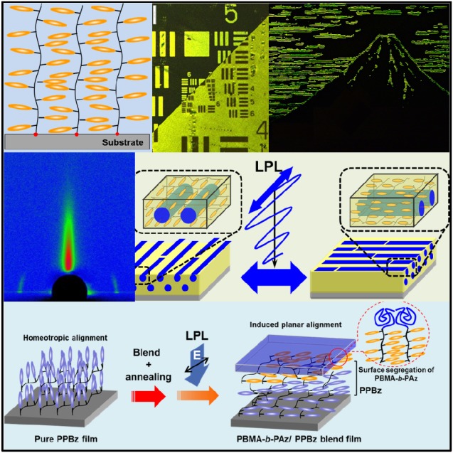
For efficient photoresponses of liquid‐crystal (LC) azobenzene (Az) polymer systems, planar LC orientation of the Az mesogenic group is required because the light irradiation process usually occurs with normal incidence to the film surface. However, LC molecules with a rodlike shape tend to orient perpendicularly to the film surface according to the excluded volume effect theory. This review introduces new approaches for inducing planar orientation in side‐chain LC Az polymer films via interface and surface molecular designs. The planar orientation offers efficient in‐plane photoalignment and photoswitching to hierarchical LC architectures from molecular LC mesogens and LC phases to mesoscopic microphase‐separated structures. These approaches are expected to provide new concepts and possibilities in new LC polymer devices.
Keywords: block copolymers, interfaces, liquid crystals, photoalignment, surface chemistry
1. Introduction
The orientation of liquid crystals (LCs) is strongly influenced by the boundaries of the interface or surface.1 The LC alignment technique using a mechanically rubbed polymer interface is widely recognized as being an indispensable technique for the production of liquid‐crystal display devices with low‐molecular‐weight LCs.2 Currently, LC photoalignment, which uses photochemical reactions at the surface of the substrate or polymer layers,3 has become increasingly important for the production of LC display panels with high resolution and contrast.4 However, because polymer LCs that can be formed and molded into films or fibers are often in contact on the “free” interface (surface), LC orientation at the surface becomes important in their applications. The LC orientation of rodlike LC molecules in a solid interface generally tends to be oriented parallel to a substrate plane (random planar orientation) due to the excluded volume effect for both low‐molecular‐weight LCs and polymer LCs.5 At the free interface, by contrast, because no interaction induces the excluded volume effect, the LC molecules exhibit a strong tendency to orient perpendicular (homeotropic) to the interfacial plane to reduce the excluded volume.5 In particular, free‐standing films of side‐chain LC polymers preferentially adopt a homeotropic LC orientation. Random‐planar‐oriented films of side‐chain liquid‐crystalline polymers (SCLCPs) are difficult to produce, even when using LC alignment layers and high‐surface‐tension substrates.
The photoisomerization of azobenzene (Az) is the most widely used and significant photochemical reaction in application studies for photofunctional materials.6 In LC materials, the trans form of Az can behave like a typical LC mesogenic group due to its rodlike shape, whereas the cis form produced by photoisomerization has a non‐mesogenic bent structure.6 The photoinduced phase transition of LC Az materials utilizes the photochemical aspects.[6, 7] Moreover, when Az‐containing LC films are irradiated with linearly polarized light (LPL), the Az mesogens can be preferentially aligned perpendicular to the actinic electric field (E) of LPL.[6, 7] Therefore, many types of photofunctionalities utilizing these Az properties have been proposed and demonstrated in Az‐containing LC molecular and polymer systems.6 In the case of SCLCPs containing Az mesogens, in particular, the LC orientation and the aggregation structure strongly depend on the side‐chain structures and the rigidity of the main chains.[3d] Therefore, molecular polymer designs of Az polymers are important for their photoresponse. Menzel and Stumpe et al. have intensively studied the LC orientations and aggregation of the side‐chain Az mesogens in the rigid rod main chain.[7e,f]
This review focuses on the in‐plane (azimuthal) photoalignment process in side‐chain LC Az polymer films. For efficient photocontrol of the azimuthal orientation of molecular LC mesogens and nano‐ordered architectures in Az‐containing LC systems, favorable designs for LC orientation are required. For effective light absorption, the transition moment of the mesogenic Az should be oriented parallel to the E (Figure 1a). However, for the reason described above, Az mesogenic groups in LC Az polymers preferentially orient perpendicular to the free interface (air‐contacting surface) plane in film states by self‐assembly (Figure 1b). Because photoirradiation processes typically occur with normal incidence to the film (substrate) plane, this LC orientation is unfavorable to absorbing light. To realize the planar molecular orientation for efficient light absorption in the LC polymer film, specific designs and strategies must be utilized to control molecular orientation (Figure 1c). This manuscript presents an overview of the molecular interface and surface design to realize the induced planar mesogen orientation for SCLCPs containing Az mesogenic groups in a thin film.
Figure 1.
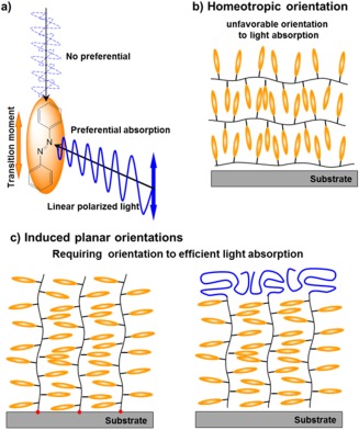
(a) Preferential absorption of azobenzene chromophore. (b) Side‐chain liquid‐crystalline polymers with rodlike mesogens typically adopt a homeotropic orientation, which is unfavorable for light absorption by normal incident irradiation. (c) To realize the efficient photoreaction, molecular design at the interface and surface is required. High‐density surface‐grafted polymer‐brush films (left) and induced planar orientation by the surface modification of the block copolymer surface segregation (right).
2. High‐Density Surface‐Grafted LC Polymer Chains
High‐density surface‐grafted polymer brushes with well‐defined structures have been realized by using surface‐initiated living radical polymerizations, such as atom‐transfer radical polymerization (ATRP).8 Because ATRP is applicable to various functionalized monomers, many types of polymer brushes have been studied, such as thermoresponsive polymers,9 photofunctional molecules,10 electrochemical units,11 ionic polymers,12 and LC polymers.13 Regarding LC polymer brushes, several reports have studied non‐photoresponsive LC brushes.13 Peng et al. synthesized side‐chain‐type LC polymer brushes through free radical polymerization in an attempt to create LC alignment layers.[13a,b] The polymer chains in this case exhibited high polydispersities and thus planar alignment was not achieved without the pretreatment of rubbing the substrate. In contrast, Hamelinck et al. synthesized nematic LC polymer brushes by surface‐initiated ATRP and found that the mesogens aligned homeotropically.[13c] The orientation control between the homeotropic and homogeneous alignments of nematic LC molecules was achieved on a patterned surface of grafted and non‐grafted regions. However, these reports have not sufficiently shown the polymer structure and side‐chain orientation.
Using the surface‐initiated ATRP method, we synthesized a side‐chain LC Az polymer brush.14 In the surface‐grafted film, the Az mesogens were preferentially oriented parallel to the substrate plane, as determined by UV absorption spectroscopy (Figure 2b). Interestingly, grazing‐incidence small‐angle X‐ray scattering (GI‐SAXS) measurements revealed that the lamellar structure of the smectic LC phase was oriented perpendicular to the substrate (random planar orientation, Figure 2d), unlike the homeotropic orientation of the spin‐cast films of the LC Az polymer (Figure 2c). The immobilized polymer terminal and sufficient brush density induce the random planar orientation of the smectic LC phase by self‐assembly. As mentioned above, the planar orientation of the LC Az phase is expected to be advantageous for angle‐selective photoisomerization and photoreorientation due to efficient light absorption. In fact, highly ordered in‐plane photoalignment was attained by LPL irradiation in the vertically oriented smectic phase of the grafted film.15 The optical order parameter S [=(A ⊥ − A ǁ)/(A ⊥ + A ǁ)], where A ǁ and A ⊥ denote absorbance at the peak of the π–π* transition band (around 336 nm) measured with polarized light set parallel and perpendicular to the realigned actinic LPL irradiation, respectively, is useful for evaluating the in‐plane anisotropy of the films. The surface‐grafted chain reached approximately S = 0.50 by LPL irradiation at 436 nm and 300 mJ cm−2 (Figure 3b). The formation of the in‐plane‐aligned monodomain smectic structure was observed as highly anisotropic scattering in GI‐SAXS measurements. On the other hand, the spin‐cast film of the same LC Az polymer only exhibited S = 0.24 with LPL up to 2 J cm−2 (Figure 3a) and no in‐plane anisotropic structure by GI‐SAXS measurements. The in‐plane anisotropy was induced by LPL irradiation at slightly above the glass‐transition temperature (i.e., LC phase) of the LC polymer.
Figure 2.
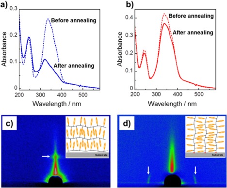
The induced planar orientation of the high‐density surface‐grafted polymer film of PAz. UV–vis absorption spectra before (dashed line) and after thermal annealing (solid line) of (a) the spin‐cast film and (b) the surface‐grafted polymer film. 2D GI‐XRD patterns of (c) the spin‐cast film and (d) the surface‐grafted polymer film. The diffraction spots are indicated as white arrows in (c) and (d). Adapted with permission from reference [14]. Copyright 2007, American Chemical Society.
Figure 3.
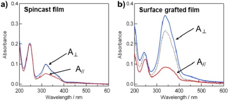
Polarized UV−vis absorption spectra of (a) the spin‐cast film and (b) the surface‐grafted film of PAz before and after exposure to LPL at 436 nm and 60 °C. Dotted and solid lines are spectra taken with a non‐polarized beam and polarized beams set perpendicular (A⊥) and parallel (A∥) to the actinic LPL at 436 nm, respectively. Adapted with permission from reference [15]. Copyright 2009, American Chemical Society.
Recently, the fabrication of the high‐density LC polymer brush was shown to not be limited to the surface‐initiated ATRP method. We prepared a high‐density side‐chain LC polymer brush with a norbornene backbone by a surface‐initiated ring‐opening metathesis polymerization (ROMP, Figure 4a).16 The ROMP LC brush adopted a vertical alignment smectic phase (random planar orientation) and exhibited a highly ordered in‐plane aligned structure by LPL irradiation. The ROMP method has the advantage of tolerability to oxygen; thus, it can produce longer grafted chains. ROMP‐grafted chains are expected to serve as a new method for expanding the applications of polymer brushes.
Figure 4.
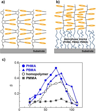
(a) Surface‐grafted side‐chain LC Az polymer film by surface‐initiated ring‐opening metathesis polymerization. (b) Surface‐grafted side‐chain LC Az diblock polymer films with amorphous blocks. (c) Orientational order parameters (S) obtained after 436 nm LPL irradiation at 500 mJ cm−2 and various temperatures for homopolymer and diblock copolymer brushes with amorphous alkyl methacrylate chains of different T g values. Adapted with permission from references [17a,b]. Copyright 2012 and 2013, American Chemical Society.
Very recently, LC polymer brushes were expanded to block copolymer systems. We introduced amorphous blocks with various T g values, such as poly(hexyl methacrylate), poly (butyl methacrylate), and poly(methyl methacrylate), between the LC Az block and the solid substrate (Figure 4b).17 In these diblock copolymer brush films, the structure and orientation of the LC Az smectic phase were essentially the same as those of the LC Az homopolymer chain attached to a solid substrate. However, the photoalignment behavior was strongly dependent on the physical properties of the amorphous block layers (Figure 4c). When the amorphous polymer layers exhibited a rubbery state (above T g), in‐plane‐aligned films with a high order parameter (S) were obtained by LPL irradiation at the optimized temperature (70–80 °C).[17a,b] The values of S were observed to be higher than those of a homopolymer brush. In contrast, optical dichroism was negligibly observed in the LC Az brush grafted onto a glassy PMMA layer after LPL irradiation.[17c] Therefore, the flexible nature of the rubbery amorphous polymer layer plays an important role in the motions for molecular Az mesogens and LC domains (lubricant effect).17 In addition, the length of the flexible layer also influences the photoalignment behavior, and longer chains can cause a higher value of S.[17c]
The high‐density LC polymer brushes containing a photoresponsive Az mesogenic group significantly enhance the photorealignment behavior due to the unique random planar orientation of the smectic LC phase. The brush films essentially possess identical thermotropic LC properties as the as‐cast films of the polymer with the same chemical structure, whereas the molecular and smectic layer orientations are completely different. Surface‐grafted polymer films with highly in‐plane LPL‐responsive mesogenic groups will provide new types of optically functional surfaces, alignment layers for liquid crystals, and smart surfaces that exhibit anisotropic friction properties. Recently, side‐chain LC Az polymer brushes were further applied to photoswitchable surfaces and photomechanical materials.18
3. Active Photoalignment of Block Copolymer Thin Films
Block copolymers can form spontaneous ordered morphologies, such as spheres, cylinders, and lamellar phases (microphase‐separated (MPS) structures).19 The length of the ordered structure depends on the radius of gyration of the polymer coils. The size of the phase separations of block copolymers typically ranges from 10 to 100 nm. The MPS structures are promising candidates for the next generation of nano‐lithographic applications. Therefore, alignment techniques for the MPS structure are a subject of intensive research. The alignment of the MPS structure has been attained by the application of external fields such as shear, electric and magnetic fields, solvent evaporation flows, and surface alignment such as topographical and surface wetting nanopatterns.20 Thermotropic LC polymers incorporated into the MPS structure can offer a hierarchically orientational molecular order that forms phase separation structures in different ways.21 Particularly in the case of SCLC block polymers, the interfaces divided between blocks are usually formed parallel to the orientation of the side‐chain mesogens. Therefore, the orientation of the MPS structure in the LC block copolymers strongly depends on the manner of LC block orientation.21, 22 Iyoda and co‐workers demonstrated a highly ordered vertical cylinder structure with a homeotropic orientation of a smectic LC Az polymer matrix by self‐assembly in thin films of the amphiphilic LC block copolymer.23 Zhao et al. showed the orientational cooperative manner in an LC Az block copolymer.24 These polymers are good examples of the cooperative alignment of LC and MPS structures in LC block copolymer thin films.
The first demonstrations of the in‐plane photoalignment for the MPS structure were reported around the same time by two independent groups, Yu et al.25 and our group.26 The in‐plane alignment of the MPS cylinder structure was conducted by LPL irradiation onto an LC Az block copolymer with a polyethylene oxide (PEO) block. Furthermore, we proposed the rewritable process of the in‐plane and out‐of‐plane alignment for MPS cylinders in LC Az possessing polystyrene (PS) blocks by combining LPL and non‐LPL irradiation (3D alignment).27 The mesogens and amorphous cylinders for these LC Az block copolymers connected with PEO and PS orient vertical to a substrate plane (homeotropic alignment). Therefore, these photoalignment processes of thin films could require particular LPL irradiation conditions such as a polymer ultrathin film state26 or monoaxial growth of an LC phase from the isotropic phase through an adequate cooling process.27
The above‐described photoalignment of MPS structures applies to “static (passive)” nanopatterns and nanotemplates. By contrast, recently we proposed that the LC Az block copolymer system with a low T g amorphous PBMA block could actively switch the in‐plane photoreorientation of MPS structure under the LC temperature of the smectic A phase of this LC Az block (“active” photoalignment, Figure 5a).28 The active photoalignment can repeat the in‐plane orientational switch of MPS cylinders for several minutes with multiple azimuthal angles by LPL irradiation as many times as desired. In this system, the LC Az block copolymer linked to a PBMA block with low T g around room temperature exhibited high plasticity in the smectic A phase of this LC polymer block (PBMA‐b‐PAz, Figure 5b). The characteristic feature of the LC block copolymer was that the Az mesogens and PBMA cylinders adopted a planar orientation by self‐assembly (Figure 5c), unlike the previous PS block case. The planar orientation character provided the high efficiency of the in‐plane photoalignment and photoswitching in the MPS structures.
Figure 5.
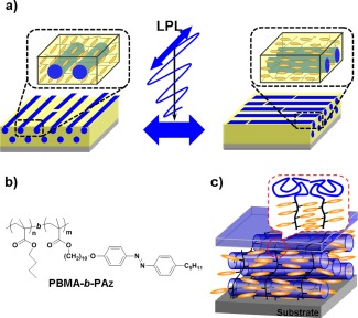
(a) Schematic illustration of isothermal in‐plane photoswitching of microphase‐separated (MPS) cylinder structures in a poly(butyl methacrylate)‐b‐PAz (PBMA‐b‐PAz) film (active photoalignment). (b) The chemical structure of the polymer and (c) schematic image of the orientation of the LC phase and MPS structure in the thin film. The low surface free energy PBMA block preferentially forms a surface segregated layer (Figure 1c, right).
Interestingly, the photoswitching system offered the opportunity for understanding the mechanisms of the photoalignment and photoswitching phenomena in LC Az block copolymer films.28 The real‐time observations of the photoswitching of the LC phase and MPS were conducted by in situ GI‐SAXS measurements using a synchrotron radiation source. In the initial state, the LC Az mesogens and MPS cylinders prealigned monoaxially via initial LPL irradiation under the smectic A phase. The successive LPL with polarization then rotated azimuthally by 90° from the initial LPL direction (realigned process). The scattering due to the LC phase and the MPS cylinder in the realigned process were detected in real‐time by a CCD camera with an X‐ray image intensifier (Figure 6, top). Figure 6 shows the time‐resolved scattering intensity profiles due to the Az LC phase and PBMS cylinders under irradiation. From the initial aligned state, the scattering for smectic LC phase and MPS cylinders quickly decayed within approximately 40 s (Figure 6a,d). The orthogonally oriented structure of these nanostructures then appeared slowly for 300 s (Figure 6b,c). These results reveal that the dynamic in‐plane photoreorientation involves the synchronized motion of the LC phase and cylinder domains (Figure 7a,b). Most interestingly, the motions of the two different hierarchies of the LC phase (molecular level) and MPS domains (mesoscopic level) were strongly cooperatively coupled and synchronized in the active photoalignment systems.
Figure 6.
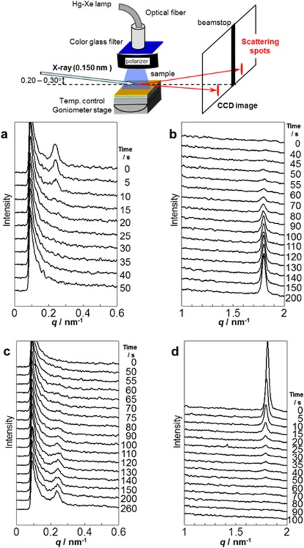
Time‐resolved scattering profiles taken under LPL irradiation with E set parallel to the Az mesogenic group at 95 °C. (a) Decay of the peak due to the loss of order in the PBMA cylinder array. (b) Progress of the peak due to the ordering of the LC Az layer of P5Az10MA. (c,d) The corresponding reversed processes under irradiation with E set orthogonal to the initial direction of irradiation. Adapted with permission from reference [28]. Copyright 2012, John Wiley & Sons.
Figure 7.
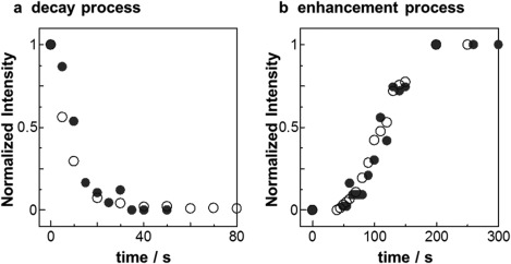
Time‐course profiles of the scattering intensity normalized to the maximum of each peak in Figure 6. (a) Decay processes due to the loss of periodic ordered structures of both the smectic Az LC (open circles) and the PBMA cylinders (full circles) observed with the appropriate X‐ray beam direction (orthogonal with each other for the two hierarchical structures). (b) Enhancement processes ascribed to the ordering of the periodicity of the two hierarchical structures. Adapted with permission from reference [28]. Copyright 2012, John Wiley & Sons.
Very recently, we proposed detailed mechanisms and pathways for the dynamic photoalignment system (Figure 8).29 The orientationally intermediate structure in the dynamic photoalignment system was captured and evaluated by real‐space microscopy observations. The smectic layers and MPS cylinder structures are retained in the orientational LC domains at the intermediate state even under highly fluctuating conditions. This indicates that the orientational photoswitching occurred via the domain rotation pathway, which demonstrates strongly cooperative motions over the hierarchies of the molecular systems.
Figure 8.
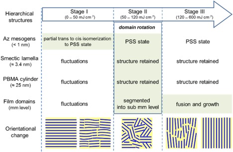
Diagram of the photorealignment process focusing on various hierarchical structures in the PBMA‐b‐PAz film. PSS stands for the photostationary state. The major motions occur in the highlighted regions.
4. Induced Planar Orientation via Surface Segregation of a Block Copolymer
In the previous section, Az LC mesogens and MPS cylinders always adopted planar orientation (oriented parallel to the substrate) of the PBMA‐b‐PAz system in thin films by self‐assembly after annealing (Figure 5c).28, 29 This characteristic feature is attributed to the segregated PBMA block layer at the topmost surface of the film.30 The lower surface free energy of the PBMA block and high flexibility induce the preferential segregation to the free surface side in the film. Thus, the PBMA layer is located at the topmost surface. Originating at the PBMA surface segregation, consequently, the MPS interface between the PBMA and PAz blocks preferentially forms parallel to the topmost PBMA layer (i.e., the free surface).
The surface segregation due to the low surface free energy PBMA block could be applied to polymer blend films of PAz homopolymer (Figure 9a).30 The PAz film mixed with a small amount of PBMA‐b‐PAz exhibited random planar orientation after annealing (Figure 9c) and highly efficient in‐plane photoalignment and photoswitching. Without PBMA‐b‐PAz, as mentioned, the pure PAz homopolymer with a smectic phase strongly exhibited homeotropic orientation, which is an unfavorable orientation for the in‐plane photoalignment process (Figure 9b). In that case, scattering corresponding to the smectic lamellar layer (d = 2.9 nm) was observed in the out‐of‐plane direction by GI‐SAXS measurement (Figure 9d). In contrast, the PAz blend film mixed with 10 wt % of PBMA‐b‐PAz resulted in a different outcome from the original homopolymer film. The lamellar scattering peaks (d = 3.4 nm) in the mixed film were only observed in the in‐plane direction (Figure 9e). This result clearly demonstrates that the induction of the planar alignment of smectic LC Az is attributable to the mixing with PBMA‐b‐PAz.
Figure 9.
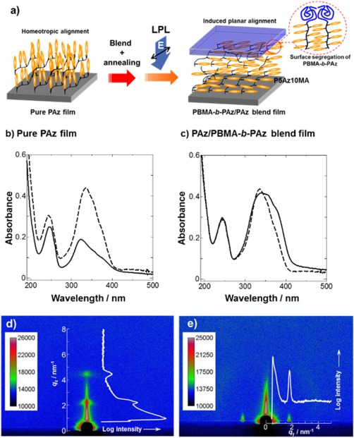
(a) Schematic illustrations of the induced planar orientation and photoalignment processes for a PAz homopolymer film with the surface‐segregated PBMA‐b‐PAz layer. UV absorption spectra of (b) the pure P5Az10MA and (c) the PBMA‐b‐P5Az10MA (10%)/P5Az10MA blend films. The dashed and solid lines indicate the spectra before and after annealing at 130 °C for 10 min. The 2D GI‐SAXS images of (d) the pure P5Az10MA and (e) the PBMA‐b‐P5Az10MA (10%)/P5Az10MA blend films after annealing at the same conditions. In the images, 1D intensity profiles are indicated as white lines.
In this regard, the effect of the PBMA‐b‐PAz addition also led to planar alignment for the MPS cylinder structure of an LC block copolymer film (Figure 10a).30 The polystyrene‐based LC block copolymer (PS‐b‐PAz) exhibited perpendicular orientation of PS cylinders in the homeotropically aligned LC phase.26, 29 At the film surface, a hexagonal cylinder array with an average spacing of approximately 47 nm was observed by atomic force microscopy (AFM) measurements (Figure 10b). With the addition of a small amount of PBMA‐b‐PAz, after annealing, scattering peaks of the smectic layer were observed in the in‐plane direction in a similar manner to the film mixed with PAz homopolymer. In this case, no morphological features were observed in an AFM image (Figure 10c). These features indicate that the planar alignment of LC mesogens and PS cylinders is induced by the segregation at the topmost surface of the PBMA amorphous layer of PBMA‐b‐PAz. The cross‐sectional profiles in the photoaligned PS‐b‐PAz film with the addition of PBMA‐b‐PAz were observed by transmission electron microscopy (TEM) observation (Figure 10d). The TEM image demonstrates that the topmost layer (ca. 20 nm) of PBMA‐b‐PAz segregated to the free surface. In addition, the mixing of the same amount of PBMA homopolymer did not lead to this effect, suggesting that the orientational alternation requires the MPS interface formation between PBMA and PAz.
Figure 10.
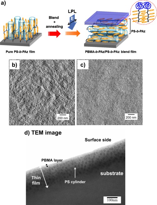
(a) Schematic illustrations of the induced planar orientation and photoalignment processes for a PS‐b‐P5Az10MA film with the surface‐segregated PBMA‐b‐PAz layer. 2.0 × 2.0 μm AFM images (phase mode) of (b) annealed PS‐b‐P5Az10MA and (c) PBMA‐b‐P5Az10MA (10%)/PS‐b‐P5Az10MA blend films. (d) Cross‐sectional TEM image of the PBMA‐b‐P5Az10MA (10%)/PS‐b‐P5Az10MA blend film. The sample was sliced in the direction parallel to the actinic LPL. Adapted with permission from reference [30]. Copyright 2013, John & Wiley Sons.
5. LC Photoalignment Molecular System from the Free Surface (Command Surface from the Free Surface)
Traditionally, the rubbing process on a polymer film surface has been the standard procedure for LC alignment control in the production of LC devices.2 Very recently, the LC photoalignment process using photoreactions at polymer surfaces has been adopted in the commercial production of LC displays.3 These surface alignment processes for LC devices have been primarily conducted through alignment effects from the solid substrate.2, 3 In comparison, the induced planar orientation via the surface segregation of a block copolymer can be regarded as an LC alignment technique from the free surface. In our results described in the previous section, the LC polymer films were composed of photoresponsive Az side‐chain polymers. This approach could be adapted for the photoalignment of non‐photoresponsive LC polymer films via the surface segregation of the photoresponsive PBMA‐b‐PAz layer at the free surface (Figure 11).31
Figure 11.
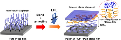
Schematic illustrations of the induced planar orientation and photoalignment process for a non‐photoresponsive SCLC polymer film with a surface‐segregated PBMA‐b‐PAz layer.
The surface‐segregated layer of PBMA‐b‐PAz behaves as a free‐surface command layer for side‐chain LC polymer films containing a phenyl benzoate (PPBz, Figure 12a).31 Pure PPBz exhibits homeotropic alignment in a thin film after annealing (Figure 12b). The scattering due to the smectic lamellar layer of PPBz was observed in the out‐of‐plane direction with d = 3.2 nm in the GI‐SAXS 2D profile (Figure 12c). As expected, in the PPBz film upon adding 3 wt % of PBMA‐b‐PAz, the scattering attributed to the PPBz smectic layer (d = 2.9 nm) was only observed in the in‐plane direction after the annealing process (Figure 12d), indicating that the random planar alignment of the mesogens in PPBz was induced by the addition of a small amount of PBMA‐b‐PAz. The surface segregation of the PBMA layer of surface‐active PBMA‐b‐PAz led to the alternation of the LC orientations as in the previous PAz homopolymer case.
Figure 12.
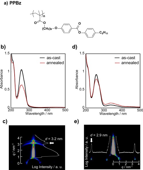
(a) Molecular structure of PPBz. Absorption spectra of (b) pure P5PB6MA and (d) PBMA‐b‐PAz (3%)/PPBz films. The solid and dashed lines indicate before and after annealing at 125 °C for 10 min, respectively. (c,e) The 2D GI‐SAXS images are shown for the above corresponding films from (b) and (d), respectively. Adapted with permission from reference [31]. Copyright 2014, Nature Publishing Group.
By the surface segregation of the surface‐active and photoresponsive PBMA‐b‐PAz, random planar orientation of the non‐photoresponsive PPBz smectic phase was attained. The next challenge was the photoalignment of the non‐photoresponsive LC polymer layer using the surface‐segregated photoresponsive Az layer. The photopatterning of the in‐plane alignment was achieved by LPL irradiation at the LC temperature of PPBz (Figure 13a,b).31 First, LPL pre‐irradiation was conducted over a whole film area, and successive patterned LPL was irradiated in the oblique direction with a rotating polarizer. Under crossed Nicols, the clear birefringence patterns by the in‐plane alignment of the PPBz mesogens were observed using polarized optical microscopy. The rotation of the crossed polarizers led to an alternation of the bright and dark tones. Moreover, these patterns were obtained by the overwriting process of LPL, indicating that this patterning process is rewritable. Additionally, note that non‐photoresponsive mesogens up to 10 μm thick can be oriented by a photoresponsive PBMA‐b‐PAz top layer with a thickness of approximately 20 nm at the free surface. Thus, the photoresponsive skin layer can direct the orientation of a non‐photoresponsive mesogen layer that is approximately 500 times thicker.
Figure 13.
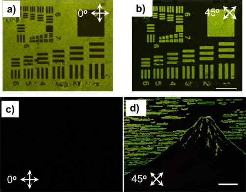
(a,b) POM images of the in‐plane photoalignment patterned film under crossed polarizers that were rotated from each other (scale bar 100 μm). After annealing at 125 °C for 10 min, the film was irradiated with LPL at 600 mJ cm−2 over the whole area, and subsequently patterned using irradiation with LPL rotated 45° through a photomask. (c,d) POM images of the in‐plane and out‐of‐plane patterned film by inkjet printing under crossed polarizers 45° from one another (scale bar 200 μm). Note that the positive and negative patterns of the images were fully switched. Adapted with permission from reference [31]. Copyright 2014, Nature Publishing Group.
To directly demonstrate the dominant effect on the LC orientation at the free surface, PBMA‐b‐PAz was overcoated onto the homeotropic‐oriented PPBz film using the inkjet printing method.31 After overcoating PBMA‐b‐PAz on an annealed PPBz film, it was subsequently annealed above the isotropic point, and LPL irradiation at the LC temperature was performed in the same manner. Figure 13c,d shows the birefringence patterning image of the inkjet printing method under crossed Nicols. The LC system achieved the alignment of the homeotropic and homogeneous planar modes in the unprinted and printed areas, respectively. The unprinted regions were observed as a dark field, irrespective of the rotation of the crossed polarizers. The appearance and disappearance of the printed image were observed by the rotation of the crossed polarizers by the oblique direction because the PPBz mesogens were in‐plane photoaligned in the printed area. By using various printing methods, we can draw any desired paintings and figures. Thus, the block copolymer of PBMA‐b‐PAz can be regarded as a “command surface ink”.31
6. Summary
Rod‐shaped LC molecules preferentially orient homeotropically at the free interface according to the excluded volume effect theory, which is the major reason for the homeotropic (vertical) orientation of the rodlike mesogens in the side‐chain LC polymers by self‐assembly. In the case of Az mesogens, this normal orientation is unfavorable for effective photoreactions because light irradiation is usually performed with a normal incidence. For the effective photoreaction, particularly the in‐plane photoreorientation, the random planar orientation of Az mesogenic groups should be required. In this review, we have focused on interface and surface molecular designs for inducing the in‐plane orientation of Az mesogens in LC polymer films. The in‐plane orientation of Az mesogens is attained by surface‐grafted main chains with appropriately high two‐dimensional density. Consequently, efficient photoalignment of the LC phase can be achieved via the cooperative motion of highly photoresponsive LC orientation. The surface segregation of the low surface free energy block also leads the planar orientation for PAz mesogens in block copolymer films by originating from the horizontal MPS interface at the surface layer. This unique orientation realizes the orientational photoswitching of the hierarchical LC nanoarchitecture with the strong cooperative motion of the PAz LC phase and the mesoscopic MPS cylinders. For LC polymer systems, the Az LC block copolymer with a low surface free energy block can be preferentially condensed at the free surface. The surface‐segregated photoresponsive LC layer that acts as the free‐surface command layer can induce in‐plane homogeneous alignment in LC polymer systems. These studies demonstrate the important role of the interface and surface molecular designs in the orientation of an LC polymer system. We hope that the new approaches for LC orientational control in this article provide new possibilities for new LC polymer devices.
Acknowledgements
I appreciate Prof. Takahiro Seki of Nagoya University for his encouragement, kind expostulations, understandings, and considerations in this study. I thank Assistant Professor Mitsuo Hara of Nagoya University for his kind support. I am thankful for the significant experimental efforts and results of Dr. Takayuki Uekusa, Dr. Yuichi Morikawa, Dr. Hafiz Ashraful Haque, Mr. Yusuke Koizuka, Mr. Tomoya Murase, Dr. Masami Sano, Dr. Kei Fukuhara, Mr. Yuki Nagashima, and many graduate students in our laboratory at Nagoya University. The real‐time in situ GI‐SAXS observation studies were collaborative work with Assistant Professor Yuya Shinohara and Prof. Yoshiyuki Amemiya of the University of Tokyo. This work was supported by a Grant‐in‐Aid for Scientific Research (B: 25286025) from JSPS and the PRESTO Program from JST.
Biography
Shusaku Nagano is an Associate Professor at Nagoya University Venture Business Laboratory. He received his B.S. (1995) and M.S. (1997) degrees in chemistry from Gakushuin University and his Ph.D. degree (2001) from Tokyo Institute of Technology under the supervision of Prof. Takahiro Seki. From 1998 to 1999, he worked in the Central Research Laboratories at Nihon Parkerizing Co. Ltd. as a researcher. In 2001, he joined the central research center at Ricoh Company Ltd. as a researcher. In 2002, he worked as an Assistant Professor at the Graduate School of Engineering, Nagoya University. Since 2011, he has been an Associate Professor at the Nagoya University Venture Business Laboratory. He has been working on interdisciplinary research in polymer chemistry and polymer physics, focusing on liquid‐crystalline polymers, photoresponsive polymers, polymer semiconductor devices, polymer surfaces, and polymer ultrathin films.

REFERENCES
- 1.a) Mauguin C. V., Bull. Soc. Fr. Mineral. 1911, 34, 71–117; [Google Scholar]; b) Chatelain P., Bull. Soc. Fr. Mineral. 1944, 88, 105–130; [Google Scholar]; c) Cognard J., Mol. Cryst. Liq. Cryst., Suppl. 1 1982, 1–74. [Google Scholar]
- 2. Jerome B., in Handbook of Liquid Crystals, Vol. 1 (Eds.: Demus D., Goodby J., Gray G. W., Spiess H.‐W., Vill V.), Wiley‐VCH, Weinheim, 1998. [Google Scholar]
- 3.a) Ichimura K., Suzuki Y., Seki T., Hosoki A., Aoki K., Langmuir 1988, 4, 1214–1216; [Google Scholar]; b) Gibbons W. M., Shannon P. J., Sun S.‐T., Swetlin B. J., Nature 1991, 351, 49–50; [Google Scholar]; c) Schadt M., Schmitt K., Kozinkov V., Chigrinov V., Jpn. J. Appl. Phys. 1992, 31, 2155–2164; [Google Scholar]; d) Ichimura K., Chem. Rev. 2000, 100, 1847–1873. [DOI] [PubMed] [Google Scholar]
- 4.a) Chigrinov V. G., Kozenkov V. M., Kwok H.‐S., Photoalignment of Liquid Crystalline Materials, Wiley‐SID Series in Display Technology, Wiley, 2008; [Google Scholar]; b) Yaroshchuk O., Reznikov Y., J. Mater. Chem. 2012, 22, 286–300; [Google Scholar]; c) Miyachi K., Kobayashi K., Yamada Y., Mizushima S., SID Int. Symp. Dig. Tech. Pap. 2010, 41, 579–582. [Google Scholar]
- 5.a) Kimura H., Nakano H., J. Phys. Soc. Jpn. 1985, 54, 1730–1736; [Google Scholar]; b) Scaramuzza N., Berlic C., Barna E. S., Strangi G., Barna V., Ionescu A. T., J. Phys. Chem. B 2004, 108, 3207–3210; [Google Scholar]; c) Faetti S., Fronzoni L., Solid State Commun. 1978, 25, 1087–1090; [Google Scholar]; d) Ocko B. M., Braslau A., Pershan P. S., Als‐Nielsen J., Deutsch M., Phys. Rev. Lett. 1986, 57, 94–97. [DOI] [PubMed] [Google Scholar]
- 6.a) Smart Light‐Responsive Materials (Eds.: Zhao Y., Ikeda T.), John Wiley & Sons, Hoboken, 2009; [Google Scholar]; b) Photoreactive Organic Thin Films (Eds.: Sekkat Z., Knoll W.), Academic Press, San Diego, 2002; [Google Scholar]; c) Ikeda T., J. Mater. Chem. 2003, 13, 2037–2057; [Google Scholar]; d) Seki T., Nagano S., Chem. Lett. 2008, 37, 484–489; [Google Scholar]; e) Seki T., Bull. Chem. Soc. Jpn. 2007, 80, 2084–2109; [Google Scholar]; f) Seki T., Nagano S., Hara M., Polymer 2013, 54, 6053–6072. [Google Scholar]
- 7.a) Tazuke S., Kurihara S., Ikeda T., Chem. Lett. 1987, 16, 911–912; [Google Scholar]; b) Eich M., Wendorff J. H., Reck B., Ringsdorf H., Makromol. Chem., Rapid Commun. 1987, 8, 59–63; [Google Scholar]; c) Anderle K., Birenheide R., Eich M., Wendorff J. H., Makromol. Chem., Rapid Commun. 1989, 10, 1477–1483; [Google Scholar]; d) Stumpe J., Müller L., Kreysig D., Hauck G., Koswig H. D., Ruhmann R. Rübner J., Makromol. Chem., Rapid Commun. 1989, 12, 81–87; [Google Scholar]; e) Menzel H., Weichart B., Schmidt A., Paul S., Knoll W., Stumpe J., Fischer T., Langmuir 1994, 10, 1926–1933; [Google Scholar]; f) Stumpe J., Fischer T., Menzel H., Macromolecules 1996, 29, 2831–2842. [Google Scholar]
- 8.a) M, Ejaz , Yamamoto S., Ohno K., Tsujii Y., Fukuda T., Macromolecules 1998, 31, 5934–5936; [Google Scholar]; b) Tsujii Y., Ohno K., Yamamoto S., Goto A., Fukuda T., Adv. Polym. Sci. 2006, 197, 1–45; [Google Scholar]; c) Matyjaszewski K., Miller P. J., Shukla N., Immarapom B., Gelman A., Luokala B., Siclovan T. M., Kickelbick G., Vallant T., Hoffmann H., Pakula T., Macromolecules 1999, 32, 8716–8724. [Google Scholar]
- 9.a) Balamurugan S., Mendez S., Balamurugan S. S., O'Brien M. J., López G. P., Langmuir 2003, 19, 2545–2549; [DOI] [PubMed] [Google Scholar]; b) Jones D. M., Smith J. R., Huck W. T. S., Alexander C., Adv. Mater. 2002, 14, 1130–1134; [Google Scholar]; c) Suzuki H., Huda M. N., Seki T., Kawamoto T., Haga H., Kawabata K., Takeoka Y., Macromolecules 2010, 43, 9945–9956. [Google Scholar]
- 10.a) Ito S., Kuno J., Yamashita K., Ohoka M., Ohkita H., Tsujii Y., Fukuda T., Trans. Mater. Res. Soc. Jpn. 2005, 30, 687–690; [Google Scholar]; b) Piech M., Bell N. S., Macromolecules 2006, 39, 915–922. [Google Scholar]
- 11. Sakakiyama T., Ohkita H., Ohoka M., Ito S., Tsujii Y., Fukuda T., Chem. Lett. 2005, 34, 1366–1367. [Google Scholar]
- 12.a) Iwata R., Suk‐In P., Hoven V. P., Takahara A., Akiyoshi K., Iwasaki Y., Biomacromolecules 2004, 5, 2308–2314; [DOI] [PubMed] [Google Scholar]; b) Feng W., Brash J., Zhu S., J. Polym. Sci., Part A: Polym. Chem. 2004, 42, 2931–2942. [Google Scholar]
- 13.a) Peng B., Johannsmann D., Rühe J., Macromolecules 1999, 32, 6759–6766; [Google Scholar]; b) Peng B., Rühe J., Johannsmann D., Adv. Mater. 2000, 12, 821–824; [Google Scholar]; c) Hamelinck P. J., Huck W. T. S., J. Mater. Chem. 2005, 15, 381–385. [Google Scholar]
- 14. Uekusa T., Nagano S., Seki T., Langmuir 2007, 23, 4642–4645. [DOI] [PubMed] [Google Scholar]
- 15. Uekusa T., Nagano S., Seki T., Macromolecules 2009, 42, 312–318. [Google Scholar]
- 16. Haque H. A., Kakehi S., Hara M., Nagano S., Seki T., Langmuir 2013, 29, 7571–7575. [DOI] [PubMed] [Google Scholar]
- 17.a) Haque H. A., Nagano S., Seki T., Macromolecules 2012, 45, 6095–6103; [Google Scholar]; b) Haque H. A., Hara M., Nagano S., Seki T., Macromolecules 2013, 46, 8275–8283; [Google Scholar]; c) Haque H., Nagano S., Seki T., Mol. Cryst. Liq. Cryst. 2013, 583, 10–20. [Google Scholar]
- 18.a) Camorani P., Cristofolini L., Fontana M. P., Angiolini L., Giorgini L., Paris F., Mol. Cryst. Liq. Cryst. 2009, 502, 56–64; [Google Scholar]; b) Naka Y., Mamiya J., Shishido A., Ikeda T., Mol. Cryst. Liq. Cryst. 2011, 547, 142–151; [Google Scholar]; c) Wang D., Ye G., Wang X., Wang X., Adv. Mater. 2011, 23, 1122–1125; [DOI] [PubMed] [Google Scholar]; d) Lomadze N., Kopyshev A., Rühe J., Santer S., Macromolecules 2011, 44, 7372–7377. [Google Scholar]
- 19. Developments in Block Copolymer Science and Technology (Ed.: Hamley I. M.), John Wiley & Sons, Chichester, 2004. [Google Scholar]
- 20.a) Block Copolymers in Nanoscience (Eds.: Lazzari M., Liu G., Lecommandoux S.), Wiley‐VCH, Weinheim, 2006; [Google Scholar]; b) Polymer Thin Films (Eds.: Tsui O. K. C., Russell T. P.), World Scientific Publishing, Singapore, 2009; [Google Scholar]; c) Park C., Yoon J., Thomas E. L., Polymer 2003, 44, 6725–6760; [Google Scholar]; d) Luo M., Epps T. H., Macromolecules 2013, 46, 7567–7579. [Google Scholar]
- 21. Yamada M., Hirao A., Nakahama S., Iguchi T., Watanabe J., Macromolecules 1995, 28, 50–58. [Google Scholar]
- 22. Mao G., Ober C. K., Acta Polym. 1997, 48, 405–422. [Google Scholar]
- 23.a) Tian Y., Watanabe K., Kong X., Abe J., Iyoda T., Macromolecules 2002, 35, 3739–3747; [Google Scholar]; b) Komura M., Watanabe K., Iyoda T., Yamada T., Yoshida H., Iwasaki Y., Chem. Lett. 2009, 38, 408–409; [Google Scholar]; c) Asaoka S., Uekusa T., Tokimori H., Komura M., Iyoda T., Yamada T., Yoshida H., Macromolecules 2011, 44, 7645–7658. [Google Scholar]
- 24. Zhao Y., Qi B., Tong X., Zhao Y., Macromolecules 2008, 41, 3823–3831. [Google Scholar]
- 25.a) Yu H., Iyoda T., Ikeda T., J. Am. Chem. Soc. 2006, 128, 11010–11011; [DOI] [PubMed] [Google Scholar]; b) Yu H., Kobayashi T., Hu G.‐H., Polymer 2011, 52, 1554–1561. [Google Scholar]
- 26. Morikawa Y., Nagano S., Watanabe K., Kamata K., Iyoda T., Seki T., Adv. Mater. 2006, 18, 883–886. [Google Scholar]
- 27. Morikawa Y., Kondo T., Nagano S., Seki T., Chem. Mater. 2007, 19, 1540–1542. [Google Scholar]
- 28. Nagano S., Koizuka Y., Murase T., Sano M., Shinohara Y., Amemiya Y., Seki T., Angew. Chem. Int. Ed. 2012, 51, 5884–5888. [DOI] [PubMed] [Google Scholar]
- 29.a) Sano M., Nakamura S., Hara M., Nagano S., Shinohara Y., Amemiya Y., Seki T., Macromolecules 2014, 47, 7178–7186; [Google Scholar]; b) Sano M., Hara M., Nagano S., Shinohara Y., Amemiya Y., Seki T., Macromolecules 2015, 48, 2217–2223; [Google Scholar]; c) Sano M., Shan F., Hara M., Nagano S., Shinohara Y., Amemiya Y., Seki T., Soft Matter 2015, 11, 5918–5925. [DOI] [PubMed] [Google Scholar]
- 30. Fukuhara K., Fujii Y., Nagashima Y., Hara M., Nagano S., Seki T., Angew. Chem. Int. Ed. 2013, 52, 5988–5991. [DOI] [PubMed] [Google Scholar]
- 31. Fukuhara K., Nagano S., Hara M., Seki T., Nat. Commun. 2014, 5, 3321–3328. [DOI] [PMC free article] [PubMed] [Google Scholar]


