Abstract
We present the first portable, binaural, real-time research platform compatible with Oticon Medical SP and XP generation cochlear implants. The platform consists of (a) a pair of behind-the-ear devices, each containing front and rear calibrated microphones, (b) a four-channel USB analog-to-digital converter, (c) real-time PC-based sound processing software called the Master Hearing Aid, and (d) USB-connected hardware and output coils capable of driving two implants simultaneously. The platform is capable of processing signals from the four microphones simultaneously and producing synchronized binaural cochlear implant outputs that drive two (bilaterally implanted) SP or XP implants. Both audio signal preprocessing algorithms (such as binaural beamforming) and novel binaural stimulation strategies (within the implant limitations) can be programmed by researchers. When the whole research platform is combined with Oticon Medical SP implants, interaural electrode timing can be controlled on individual electrodes to within ±1 µs and interaural electrode energy differences can be controlled to within ±2%. Hence, this new platform is particularly well suited to performing experiments related to interaural time differences in combination with interaural level differences in real-time. The platform also supports instantaneously variable stimulation rates and thereby enables investigations such as the effect of changing the stimulation rate on pitch perception. Because the processing can be changed on the fly, researchers can use this platform to study perceptual changes resulting from different processing strategies acutely.
Keywords: cochlear implant, binaural, hardware, software, real-time
Introduction
Cochlear implants (CIs) are the most successful sensory prosthetic devices ever developed. They often can restore hearing and speech to a level that enables normal social communication. In these cases, they are truly transformative for their users. Nevertheless, considerable progress remains to enable CI users to hear and communicate in cocktail party environments where competing sources in reverberant rooms must somehow be separated. To make progress on this topic, the CI research community needs flexible and powerful CI research tools. Existing tools (e.g., Med-El’s RIB II and Cochlear Corporation’s NIC) are widely used and have generated many important findings; however, since each tool can only work within the limitations of the implanted part, a diversity of tools, each with its own strengths and weaknesses, will expand the types of experiments that can be done. The Oticon Medical CI human interface research platform (cHIRP) extends existing CI research capabilities by providing a tool that specializes in real-time binaural processing, which is not well supported by other systems. The platform named cHIRP synchronously drives two independent bilateral Oticon Medical SP or XP implants to produce fine-grained interaural time difference (ITD) and interaural level difference (ILD) cues. In addition, the platform also supports variable stimulation rate processing for studying the effect of stimulation rate on perception (e.g., the effect of this rate on pitch). We hope this platform will enable researchers to generate data that can ultimately help improve the listening lives of all CI users.
System Overview
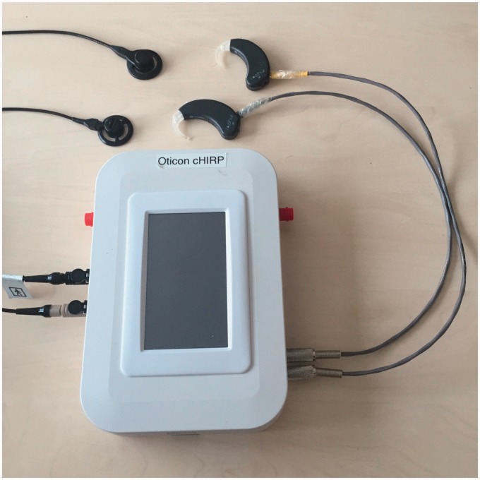
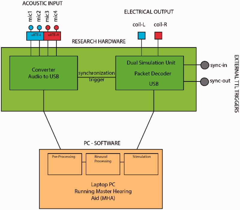
The cHIRP platform (Figure 1) consists of bespoke hardware and PC-based software joined via USB (Figure 2). The hardware parts are responsible for (a) providing a four-channel binaural ear-worn microphone system, (b) digitizing these four audio signals synchronously, and (c) generating the final left and right synchronized coil outputs needed to drive two SP or XP implants. Although we focus here on bilateral configurations, monaural implants and the binaural SP implant are also supported but these cannot provide ITD cues. The software parts are responsible for all processing tasks including (a) performing user-defined preprocessing on the digitized audio and then (b) using a commercial or user-defined stimulation strategy to generate two synchronized electrodograms. The PC-based software is called the Master Hearing Aid (MHA) and includes a flexible PC-based programming environment. The software architecture is open and the MHA can be extended: Any imagined processing or stimulation strategy (within the capabilities of the target SP or XP implants) can be programmed and tested in CI users without the need to create new hardware.
Figure 1.
Picture of the included hardware parts of the cHIRP research platform. The stimulation hardware box, the supplied BTE microphones, and supplied output coils and leads (1 m) are also shown. BNC input and output triggers are visible in red but USB cables and feedback LEDs are not shown.
Figure 2.
Block diagram of the cHIRP research platform showing the hardware parts (green, red, and blue) and the software parts (orange). These are connected via USB.
In summary, the cHIRP research platform can be thought of as a fully programmable binaural behind-the-ear (BTE) device for Oticon Medical CIs. It provides a complete signal processing chain for developing, implementing, and evaluating state-of-the-art preprocessing algorithms and stimulation strategies—or indeed completely new ones—in real-time.
Microphone Inputs
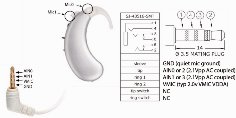
Audio input consists of four input microphones, two on a right BTE and two on a left BTE. The microphones are modified BTE microphones used in Oticon Medical systems and are frequency corrected and calibrated to ±2 dB. The microphones interface with the cHIRP platform via two standard four-connector 3.5-mm stereo jacks (Figure 3). Currently, the microphones are battery powered (2 × 675 button cells), but the board can supply clean microphone power.
Figure 3.
A single modified BTE (one of two supplied with the cHIRP platform). The pinout for the jack is shown. Normal stereo plugs can also be used to accept direct inputs.
The modified BTE microphones have an input dynamic range (35–103 dB SPL) and sensitivity of 0.25 Vrms/Parms. This creates enough quantization levels to represent well the typical sound levels used for testing (55–75 dB SPL; Table 1).
Table 1.
BTE Microphone Output and ADC Performance.
| Item | Min | Typical | Max | Units |
|---|---|---|---|---|
| Input sound level | 35 | [55,75] | 103.56 | dB SPL |
| Output voltage | 0.8 | [8, 79.6] | 2131 | mVpp |
| Approx. ADC decimal span (pp) | 24.6 | [246, 2448] | 65535 | decimal |
| Noise floor | 30 | [30, 34] | 35 | dBA |
Note. ADC = analog-to-digital converter.
Stimulation Hardware
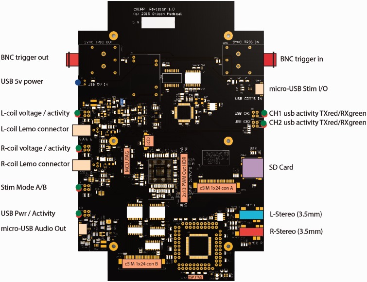
The cHIRP stimulation hardware enclosure (Figure 1) has dimensions of 20 × 13 × 4 cm and houses a bespoke printed circuit board (Figure 4). It is responsible for handling all real-world signals and communicating with the MHA processing software. The main tasks of this board include (a) digitizing the acoustic input, (b) providing a first-in-first-out (FIFO) buffer and robust communication protocol for receiving commands, (c) producing the outputs needed to drive two CIs, and (d) providing triggering and synchronization of all signals. It is powered by USB with medical-grade isolation on the output side.
Figure 4.
cHIRP research platform hardware diagram labeled to indicate all connectors and user feedback LEDs.
The board has two independent sections, each powered by a separate USB. The audio input section receives four channels of acoustic input from the supplied ear-worn BTEs through two standard 3.5-mm stereo jacks (other stereo sources may also be used). These four signals are all digitized synchronously using the same 16.667-kHz sample clock. Samples are packetized and transferred via USB to the PC-side software for processing (discussed later).
The stimulation output section receives stimulation commands from the MHA. These are staged in a seven-level FIFO, validated, decoded, and sent to the coil output drivers. Two independent onboard Oticon Medical SP or XP implant coil drivers are provided. These drivers support clinical transmission power levels from 5% to 70% in 1% steps (covering the known range of SP implant users). Coil transmission power, triggering options, and start or stop commands are also sent over USB. Exact timing of the outputs to external events can be controlled by a selection of triggers discussed in the following sections. Timing of relative interaural output (left vs. right) is encoded directly in the stimulation command packets.
MHA Software
The PC-based MHA software part of the research platform is a real-time signal processing system (Grimm, Herzke, Berg, & Hohmann, 2006). Originally designed for conventional hearing aid research, the MHA allows many different signal processing algorithms (e.g., noise reduction, beamforming, etc.) to be run in software at low latency. These algorithms can be cascaded to produce complex systems. New algorithms can be coded at any time through the MHA’s plug-in architecture.
Platform Capabilities
SP Implant Constraints
Human CI Research platforms like cHIRP are always constrained by their associated implants. The cHIRP platform is designed to work with Oticon Medical SP and XP implants; however at the time of this work, the XP implant is still in prelaunch and its capabilities are not tested here. SP implants operate in common ground mode and stimulate their electrodes sequentially from base electrode (E1) to apical electrode (E20). Their pulse shape is rectangular. With cHIRP, each electrode onset can be controlled in 0.5 µs steps relative to the previous electrode’s cessation, but this must include a minimum interelectrode gap of 15 µs. In duration coding mode, pulse widths can be individually set from 5 µs to 200 µs in 1 µs steps and a global amplitude value gathered from the patient’s fitting file (typically a number between 40 and 75) is set. Electrodes can be effectively skipped by specifying a subthreshold pulse width ≤ 5 µs.
ITD and ILD Control and Accuracy
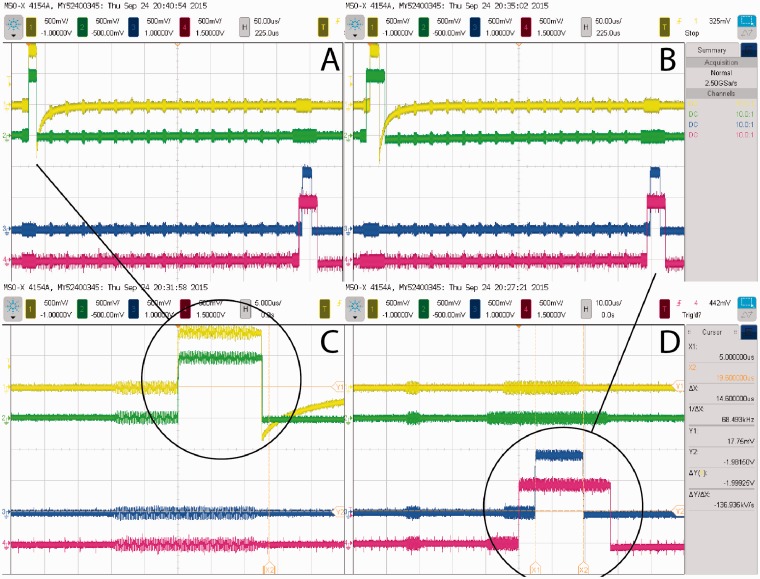
Because cHIRP focuses on binaural CI processing, its ability to control interaural electrode time differences (ITDs) and interaural electrode level differences (ILDs) is crucial. ITD and ILD performance was tested by recording directly from four electrode outputs simultaneously—two from a left SP implant and two from a right one—while binaural stimulation commands were issued over USB. Electrode pair no. 4 (CF = 4492 Hz) and pair no. 20 (CF = 260 Hz) were recorded (Table 2, Figure 5). Since Oticon Medical CI devices default to control loudness by changing pulse duration (rather than current amplitudes as used by other CI manufacturers), this mode was kept for the purposes of these tests. However, both the implants and the platform support amplitude coding as well.
Table 2.
Comparison of Command ILDs and ITDs With the Corresponding Measured Values From Paired Interaural Electrodes.
| Test no. | Electrode no. | Command ILD (µs) | Measured ILD (µs) | Command ITD (µs) | Measured ITD (µs) |
|---|---|---|---|---|---|
| Test 1 | E4 | 0.0 | 0.156 | 0.0 | 0.0 |
| E20 | 13.0 | 13.092 | 5.0 | 5.0 | |
| Test 2 | E4 | 13.0 | 13.085 | 5.0 | 5.0 |
| E20 | 13.0 | 13.094 | 5.0 | 5.0 |
Note. ILD = interaural level difference; ITD = interaural time difference.
Figure 5.
Oscilloscope traces showing the output of two binaural pairs of electrodes (yellow/green = left/right E4, blue/red = left/right E20). Panel A shows an E4 electrode pair with ITD = 0 and ILD = 0, while in the same frame the E20 pair is separately controlled to have ILD = 13 µs and ITD = 5 µs. Panel B shows a second test where the two pairs of electrodes share the same ILD = 13 µs and ITD = 5 µs. Panels C and D are zoomed versions of the pulses to illustrate the accuracy achieved. Cross talk from other electrodes is visible and useful for counting these. Charge recovery is only active for electrode E4 on the left.
The original synchronization target was set to 10 µs based on the minimum just noticeable difference of ITD for normal-hearing individuals at low frequencies (500–1 kHz; Colburn, Shinn-Cunningham, Kidd, & Durlach, 2006). Since ITD information is encoded within the stimulation packet itself, this synchronization could be completely controlled and was measured to be better than ±1 µs, controllable in 0.5 µs steps. Since one sample corresponds to 60 µs (Fs =16.667 kHz), the entire system was designed to be sample accurate and synchronous. The range of the ITDs one can present is only bounded by the stimulation rate because one stimulation must stop before another one begins.
Like all CIs, control over output levels is highly accurate. This always provides excellent ILDs for CI users. For cHIRP, an output ILD resolution of ±2% in energy terms is the worst case (worst case occurs at lowest levels, near a CI user’s perception threshold). To explain, duration-based ILDs are controllable in 0.5 µs steps, which, at typical CI threshold durations of 25 µs, correspond to 2% initial steps. For reference, the just noticeable difference in duration is ∼5 µs at low levels. For higher levels (longer durations), the achievable ILD resolution improves.
Triggers
Oticon Medical SP implants stimulate electrodes sequentially along the array from base to apex upon receiving a coil command. For the cHIRP platform, this stimulation cycle (on both the left and right implants) is timed from the same configurable global trigger. Four triggers are available: (a) an internal hardware trigger with fixed user-specified rate, (b) an external transistor-transistor logic (TTL) level trigger via BNC, (c) an audio-sync trigger which is activated on each USB audio packet transmission, and (d) an immediate trigger that stimulates immediately upon receiving a stimulation command packet over the USB.
The internally timed trigger uses the hardware FIFO and is useful for looking at how the stimulation rate of a fixed-rate strategy might affect perception for a chosen set of algorithms, but where low latency is not crucial. This trigger can be set from 1 Hz to 1000 Hz, in increments of 1 Hz. For the internal trigger, care must be taken not to overrun or starve the hardware FIFO, this is assured via a specially designed MHA output plugin, but it requires that any programmed processing be real-time such that stimulation packet generation does not exceed the chosen rate.
An external BNC trigger is provided for interfacing with other hardware, such as clinical eABR machines or for possibly connecting to some other hardware designed to control stimulation.
The audio-synchronized trigger is useful when the smallest latency is desired or when investigating the effect of latency. Because this trigger produces one output stimulation trigger for every input audio packet sent, it can bypasses the hardware’s FIFO or fill it to a set level. Here, the hardware delays can be fixed. This trigger corresponds to the default rate for Oticon Medical implants (520 Hz) and allows the lowest possible hardware latency with a FIFO level of 1.
Finally, the immediate trigger is useful for investigating the effect of variable rate strategies. Since the entire array is sequentially stimulated on each trigger, dynamically changing the global trigger rate affects all electrodes (although electrodes can be disabled). It can be used to evaluate the effect of rate on pitch for example. However, this trigger may be affected by jitter, for details, please refer to Section Latency and Jitter. Table 3 shows the possible stimulation rates for the different output trigger types.
Table 3.
Supported Output Trigger Types and Their Rates.
| Trigger type | Allowed rate |
|---|---|
| Internal | 1 to 1000 Hz (fixed) |
| External | <1000 Hz (variable) |
| Audio | 520 Hz (constant) |
| Immediate | <1000 Hz (variable) |
Latency and Jitter
Latency between audio input and electrical output needs to be kept low in order to prevent audio to lip-reading misalignment or the deterioration of speech production for test subjects. The minimum system delay for avoiding noticeable lip-sync misalignment is ∼17 ms for normal-hearing listeners. Disruption to speech from delayed auditory feedback is maximum at ∼200 ms (Jones & Striemer, 2007; Timmons, 1983; Yates, 1963). The total latency budget including the different stages of the platform was specified to be below 17 ms, as shown in Table 4.
Table 4.
Latency Components and Their Values.
| Component | Delay budget (ms) | Actual delay (ms) |
|---|---|---|
| ADC | 2.7 | 2.7 |
| Processing | 10.0 | 3.0 |
| Stimulation | 2.7 | 1.3 |
| Total | 15.4 | 6.0 |
Note. ADC = analog-to-digital converter.
The actual latency caused by the signal processing performed on the MHA depends on the algorithms used. Here (Table 4) we report the baseline latency for running the system on a small but powerful Intel NUC computer with a Core i5 processor (NUC5i5RYK) running a low-latency Linux kernel. The latency was measured using only the essential cHIRP MHA algorithms: (a) a pass-through identity plug-in, (b) an overlap-add framework, (c) a basic commercial stimulation strategy, and (d) the output plugin. With the default settings of the overlap-add framework (FFT length of 128 samples with 75% overlap) and a default sampling rate of 16.667 kHz, an average processing latency of ∼3 ms was measured. This leaves room to combine this basic setup with preprocessing algorithms like binaural noise reduction and directional filtering algorithms that might cause additional delay.
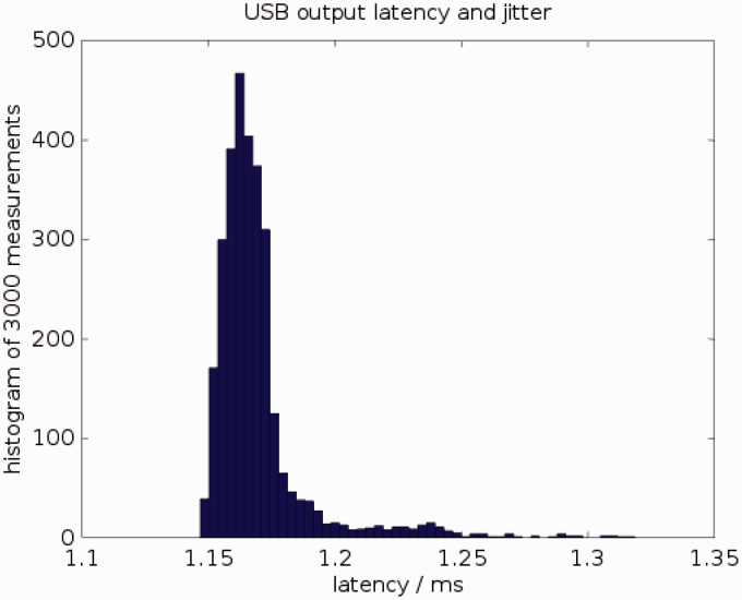
A drawback of using a PC to perform the signal processing is the time jitter caused by the interruption of the signal processing by system tasks. Figure 6 shows a histogram of the latency between sending stimulation packet to the USB driver on the computer and a hardware trigger that the cHIRP board generates at the start of the actual stimulation. Observed latencies vary between 1.15 ms and 1.32 ms. For variable stimulation rates, this jitter is equivalent to an inaccuracy of 0.9% at 100 Hz stimulation rate, 1.7% at 200 Hz, or 4.3% at 500 Hz.
Figure 6.
Latency of sending stimulation frames from the PC to the research board over USB, measured 3000 times. Mean latency = 1.17 ms; minimum latency = 1.15 ms; maximum latency = 1.32 ms. 95% of all latency values lie between 1.15 ms and 1.21 ms.
Signal Processing and Algorithm Implementation
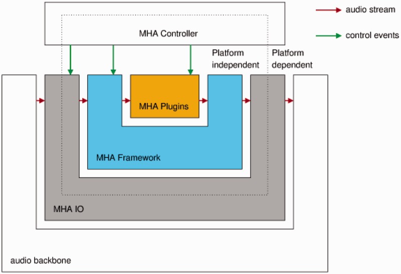
The MHA software (Grimm et al., 2006) supports algorithm developers with an extensive toolbox that can be used to quickly develop new parameterizable signal processing algorithms. It comes with a collection of ready-to-use hearing aid algorithms, which can be combined with user-developed algorithms to form a complete software hearing aid that can process signals in real-time. The MHA has a layered structure as shown in Figure 7.
Figure 7.
The layers of the master hearing aid.
The audio backbone is external to the MHA. It is an abstraction for a source and a sink for audio data. The MHA can use different audio backbones by selecting the corresponding IO library. The standard available audio backbones are (a) the file system, (b) sound card drivers, (c) the Jack, a low-latency sound server and router, and (d) network audio streams. In addition to these, for the cHIRP research platform, a special USB audio interface has been implemented to receive the four-channel input sent by the research board. The MHA framework selects the MHA IO library and passes the fragmented audio input signal to the MHA plug-ins.
Audio signal processing in the MHA is generally performed by plug-ins. Each plug-in forms one processing block; algorithms can consist of one or more plug-ins. Plug-ins can work on waveform data (time domain) or short-time Fourier transforms.
A diversity of state-of-the-art audio processing algorithms already exists as plug-ins for the MHA (e.g., noise power spectral density estimation and suppression, fixed and adaptive minimum variance distortionless response beamformers, gammatone filterbanks, a signal localization algorithm based on generalized cross correlation features with phase transform, and many more). For more examples as well as more details about the algorithms, please refer to Adiloğlu et al. (2015) and Baumgärtel et al. (in 2015a, in 2015b). Additionally, many helpful tools exist (e.g., a virtual test box to analyze level-dependent gain-frequency responses of plug-ins, or a guided calibration procedure).
The MHA comes with a basic commercial continuous interleaved sampling (CIS) strategy as a plugin, but researchers are also free to write their own or emulate other known commercial strategies.
Intended Use of the Research Platform
The cHIRP research platform will be made available to qualified researchers interested in investigating CI topics. Because the CI signal processing is carried out on a PC and is open, it is accessible to inspection and alteration. In addition to real-time binaural processing, the platform can perform data logging, play predetermined stored input signals, and allow alteration of existing algorithms and insertion of new ones.
New algorithms for the MHA are developed as plug-ins, and the signal path through the algorithms as well as algorithm settings can be altered at run time, making it possible to compare different algorithms or algorithm settings with subjective measures such as speech intelligibility, listening effort scaling, paired comparisons, and so forth.
Often in developing a hearing system, there are trade-offs to be made for example between increasing the signal-to-noise ratio of a signal and preserving binaural cues (Baumgärtel et al., in 2015a, in 2015b). Exploitation of spatial information (Adiloğlu et al., 2015) could in the future enable CI patients to better perceive the direction of sound sources and will increase their signal-to-noise ratio with the result that their speech perception in adverse listening conditions will be enhanced.
The PC running the MHA can be a portable computer, allowing the subject to carry the research platform with him or her and thereby use it outside of a laboratory. In a laboratory setting, the platform may additionally be connected to an audiological workstation, performing audiological tests by replacing the microphone input signal with the output of the audiological workstation if desired.
The MHA has been used to test different combinations of state-of-the-art speech enhancement algorithms on CI patients (Adiloğlu et al., 2015; Baumgärtel et al., in 2015a, in 2015b). On these tests, the incoming signal was enhanced in the MHA and the enhanced signal was sent to the CI device as an audio signal. The CI device converted the audio signal into electric stimulation and performed the stimulation independent of the platform. For more details about these algorithms, their evaluation and the obtained results please refer to the corresponding articles.
Two Example Scenarios
In this section, we show two examples of the cHIRP producing synchronized coil outputs in real-time. The first example shows simultaneous production of ITD and ILD cues. The second example shows a variable stimulation rate. In both examples, we used simulated audio inputs.
ITD/ILD encoding
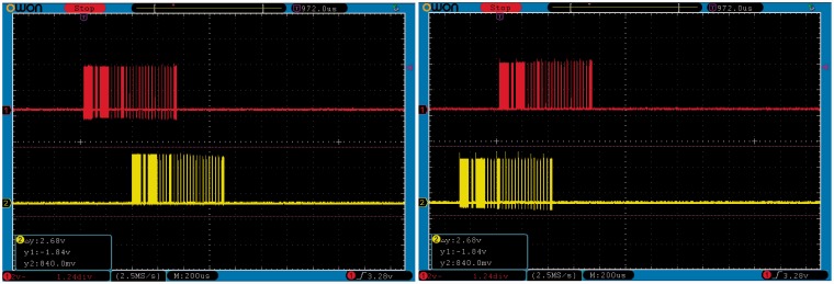
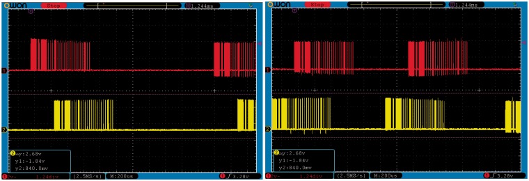
Figure 8 shows two snapshots of an oscilloscope depicting two instances of stimulation frames. These snapshots were taken during the same run of the platform at two different time instances. The bottom (yellow) traces show the digital coil control output from the cHIRP hardware for the left ear, while the upper (red) traces shows the right ear. The interaural timing of the coil outputs shows changing ITDs (+225 µs and −400 µs). The audio input used to generate these stimulation frames was moving side to side in the frontal hemisphere and was composed of one low-frequency (255 Hz) and one high-frequency (4 kHz) component. The observed delay between the upper and lower coil activity traces is caused by including the ITD for the signal position. ILDs are encoded within the trace so these are not visible directly.
Figure 8.
Interaural time and level differences between the left and right ears. Time differences appear as relative shifts of the red and yellow traces shown at two different times (left panel and right panel). Level differences are not easily visible in these plots.
Variable stimulation rates
Figure 9 shows two snapshots of the oscilloscope taken while varying the stimulation rate on the fly. The time interval between two successive coil-activity bursts changes between the left and right panel depending on the fundamental frequency of the audio input (left panel = ∼2 ms or 500 Hz, right =∼1.2 ms or 833 Hz). For this example, the fundamental frequency was predetermined, but zero crossings or other techniques could be used to extract it within the MHA.
Figure 9.
Variable stimulation rates between left and right panel.
CI User Safety
CI user safety is an important concern. There is a trade-off to be made between allowing researchers more flexibility and providing a safer system. Within cHIRP, output plugins load and check a patient fitting file for allowed T and C levels. This safety check cannot be disabled. Therefore in order to exceed these levels, a research fitting must made and it should be tailored to the planned experiment. Since increasing the stimulation rate can change loudness perception regardless of any imported fitting file, a warning is produced prior to stimulation that specifies that the current T and C levels were provided for loudness coded by duration (or amplitude) with a specific stimulation rate. The researcher must accept the warning and thereby take responsibility in order to proceed. To insure data are not corrupted in transmission (USB), the output plugin contains a 16-bit cyclical redundancy check (CRC) for each stimulation packet and these are evaluated by the receiving hardware. CRC errors cause the packet to be ignored and no stimulation will occur until a valid packet is again received.
Conclusions
The cHIRP research platform provides a flexible C-language programmable true binaural BTE replacement for Oticon Medical SP and XP implants. Its synchronized four-channel acoustic input and synchronized left/right coil outputs are ideal for investigating binaural CI processing (ITDs and ILDs) in real time. The heart of the system is the MHA, a flexible real-time PC-based software platform. Any real-time algorithm can be implemented as a plug-in within the MHA allowing arbitrary combinations of processing algorithms. In addition, stimulation strategies are also generated within the MHA so these can also be programmed—within the limits of the connected implants. The cHIRP research platform fills an important gap in CI research by providing a flexible, semi-portable, binaural real-time CI research processor for the first time. We hope cHIRP will be useful for psychoacoustic experiments on CI patients and that those data can ultimately benefit CI users everywhere.
Declaration of Conflicting Interests
The authors declared no potential conflicts of interest with respect to the research, authorship, and/or publication of this article.
Funding
The authors disclosed receipt of the following financial support for the research, authorship, and/or publication of this article: This work is supported by funding from the European Union’s Seventh Framework Programme (FP7/2007–2013) under ABCIT Grant Agreement No. 304912.
References
- Adiloğlu, K., Kayser, H., Baumgärtel, R., Rennebeck, S., Hohmann, V., & Dietz, M. (2015). A steering binaural beamforming system for enhancing a moving speech source. Trends in Hearing, 19, 1--13. [DOI] [PMC free article] [PubMed]
- Baumgärtel, R., Krawczyk-Becker, M., Marquardt, D., Völker, C., Hu, H., Herzke, T.,… Dietz, M. (2015a). Comparing binaural signal processing strategies I: Instrumental evaluation. Trends in Hearing, 19, 1--16. [DOI] [PMC free article] [PubMed]
- Baumgärtel, R., Krawczyk-Becker, M., Marquardt, D., Völker, C., Herzke, T., Coleman, G.,… Dietz, M. (2015b). Comparing binaural signal processing strategies II: Speech intelligibility of bilateral cochlear implant users. Trends in Hearing, 19, 1--18. [DOI] [PMC free article] [PubMed]
- Colburn S. H., Shinn-Cunningham B., Kidd G., Jr., Durlach N. (2006) The perceptual consequences of binaural hearing. International Journal of Audiology 45(Suppl 1): 34–44. [DOI] [PubMed] [Google Scholar]
- Grimm G., Herzke T., Berg D., Hohmann V. (2006) The master hearing aid—A PC-based platform for algorithm development and evaluation. Acta Acustica United With Acustica 92: 618–628. [Google Scholar]
- Jones J. A., Striemer D. (2007) Speech disruption during delayed auditory feedback with simultaneous visual feedback. Journal of Acoustical Society of America 122(4): 135–141. [DOI] [PMC free article] [PubMed] [Google Scholar]
- Timmons B. A. (1983) Speech disfluencies under normal and delayed auditory feedback conditions. Perceptual and Motor Skills 56(2): 575–579. [DOI] [PubMed] [Google Scholar]
- Yates A. J. (1963) Delayed auditory feedback. Psychological Bulletin 60: 213–232. [DOI] [PubMed] [Google Scholar]


