Abstract
We outline the design of a new small-animal PET system. This system employs modular scintillation cameras composed of nine PMTs coupled by a light guide to a monolithic NaI(Tl) scintillation crystal. The basic principles of the PET system are presented along with an overview of the electronics and position-estimation scheme. The potential advantages of this design are discussed and preliminary reconstructed images are presented.
I. Introduction
Interest in molecular imaging has greatly increased over the past several years, and consequently so has the number of newly proposed and constructed small-animal PET systems. These include microPET [1], [2], cMiCE [3], ClearPET [4], YAPPET [5], A-PET [6], and MMP [7]. The new systems have enhanced the capabilities of PET over a small field of view in terms of resolution, sensitivity, and expense.
One limit to further improvement in resolution and expense has been the segmented or block scintillators typically employed in both clinical and small-animal PET systems. The pixel size acts as a final limit on detector resolution and the pixelization procedure can be laborious. To circumvent these issues several efforts have been made to bring monolithic crystals to PET. Commercially, the main approach has been to convert dual-head [8], [9] or triple-head [10], [11] SPECT designs into dual-modality PET/SPECT imagers by adding coincidence electronics and thicker NaI(Tl) crystals. These systems have been able to produce acceptable images, but their performance has generally been considered inferior to that of dedicated PET systems. Specialty systems, such as the PENN-PET [12] brain imager, have also been commercialized with a combination of monolithic crystals with unique geometries. Monolithic-crystal PET devices for small-animal imaging have been proposed [13], [14] and constructed [15], [3]. The imagers discussed in [13] use Anger arithmetic, which leads to position-estimation problems – particularly near the edge of the crystal. In [3] a likelihood-based position-estimation scheme is implemented, but with the likelihood based upon combinations of position-sensitive photomultiplier (PSPMT) signals rather than all of the information that the systems can provide. In [14] full 3D position estimation is proposed, but only simulation results are presented and the likelihood model employed assumes full knowledge of the PMT output means at each 3D point within the scintillator – knowledge that might prove difficult to acquire.
We propose a new PET system based on modular cameras with monolithic scintillation crystals. Our current design uses single-anode PMTs and an electronics that allows for all PMT signals to be stored and later used to optimally estimate the position of a scintillation event. In this paper we give an overview of the system and present preliminary PET images taken with a two-camera prototype system.
II. Instrumentation
A. Modular scintillation cameras
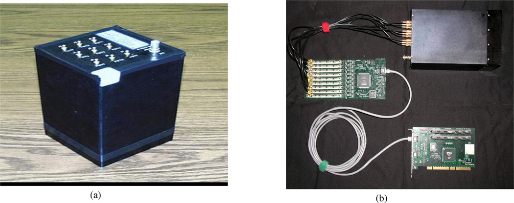
The heart of our system is our modular gamma camera [16], shown in Fig. 1(a). These cameras consist of a monolithic scintillation crystal coupled through a light guide to an array of photomultiplier tubes (PMTs) collecting the optical photons generated by a high-energy scintillation. The cameras used in this study had a 3×3 arrangement of PMT’s separated by a 15mm light guide from a 12cm×12cm×5mm crystal. Our method of position estimation, described below, is enhanced when a large number of optical photons are produced. For this reason we chose NaI(Tl) as our scintillator.
Fig. 1.
(a) The modular scintillation camera used for our PET system. (b) The electronics, including the front-end digital-to-analog and event-processing hardware, the back-end memory and PCI-interface board, and the camera.
One advantage of our monolithic-crystal cameras over block and segmented detectors is their simplicity and relatively low expense. Another is that there are no inherent limitations in resolution due to pixel size. Additionally, they do not suffer from light loss at pixel boundaries – a problem that will increase as pixel size is reduced for higher resolution. Thus, with monolithic crystals, a more noise-free signal reaches the PMTs which could potentially increase the ability to estimate the 2D (x, y) position of scintillation, and might facilitate estimation the depth of the interaction (z) as well.
B. Electronics
Our custom electronics, shown in Fig. 1(b), consist of a front-end event processing board connected via an ethernet-based protocol to our back-end storage and interface board. On the front-end board the nine PMT signals are continuously streamed through separate pulse-shaping and digitization channels into a single field-programmable gate array (FPGA). The FPGA detects events based on the sum signal and sends all nine PMT signals from the detected events to the PCI backend board. There they are stored in non-volatile memory until downloaded to computer disk.
In this version of list-mode electronics all detected attributes of a scintillation event are stored. For our PET detectors these include the digitized outputs of each of the photomultiplier tubes for a detected event along with the time when the event occurred, quantized in 30 nanosecond divisions. Since the boards from all detectors can be run off the same clock, the time stamp may later be used to determine coincidence (and is also useful when dynamic imaging is carried out). The fact that we store all PMT signals allows us to perform sophisticated analysis to determine the position of a gamma interaction.
III. Position estimation
The position-estimation procedure is carried out using a maximum-likelihood approach based on Poisson probability [17]. The log of the likelihood under the Poisson model is written
| (1) |
where L (x, y) is the log of the likelihood that the gamma interaction occurred at position (x, y), pi is the PMT output of tube i generated by the interaction, and p̄i (x, y) is the mean PMT output for tube i when an interaction occurs at position (x, y). Since we have all of the PMT signals in our list-mode output, the likelihood will be maximized over all information that the camera provides to give the best possible position estimate.
The PMT signals are not all that are required to maximize the likelihood using Eq. 1. It is also necessary to have the mean values, p̄i (x, y). These are obtained using a calibration procedure that involves moving a well collimated 99mTc source across the face of the camera on a fine grid (typically 1.5mm) and thereby obtaining the mean photomultiplier signals as a function of (x, y). The grid can later be made finer using an interpolation procedure. If an isotope other than 99mTc is used for imaging, the results are normalized to account for expected energy of the gammas and non-proportionality of the crystal light output as a function of energy [18].
IV. Results
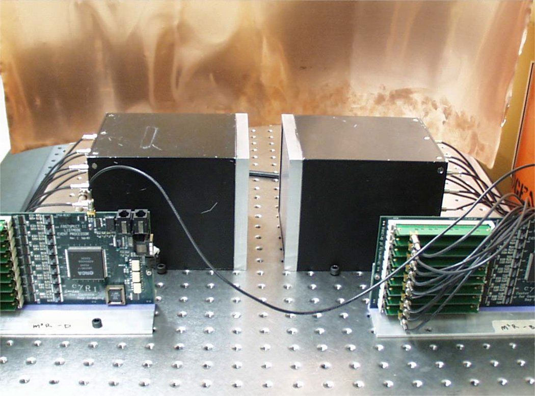
We constructed a prototype system consisting of two modular cameras with associated electronics. These cameras were positioned with a separation of 3.8cm with the space between them representing the field of view. The imaging setup is shown in Fig.2.
Fig. 2.
The imaging-system setup used during this experiment.
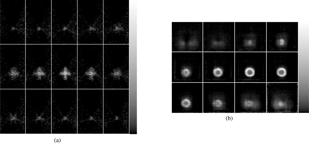
Phantoms were generated by moving a disk-shaped 22Na source about the field of view and concatenating the lists of coincidence events detected during the period of source motion. The disk had a diameter of ~4mm and a thickness of ~2mm. One phantom that we employed had the shape of (x, y, z) Cartesian coordinate axes with each axis 1.7cm in length. The 2D slices of ML-EM reconstructions, given in Fig, 3(a), show the (x, y) axes easily distinguishable, with the width of the reconstructed axes largely determined by the ~4mm diameter of the source. In the z direction, shown in the 1mm spacings between each frame, the width of the (x, y) axes appears close to the 2mm thickness of the source.
Fig. 3.
The reconstruction of (a) an object shaped like a Cartesian coordinate system and (b) a sphere of inner diameter ~10mm. The resolution is limited by the size of the source used to generate the phantom.
We also employed this method to produce a spherical phantom of outside diameter ~14mm and inner diameter ~10mm. The reconstruction of the phantom, given in Fig. 3(b), shows good definition of the sphere though, as discussed below, it is possible that even better results could be obtained if a four-camera system were used.
V. Discussion and future work
We have conceived and constructed a simple and inexpensive PET system that has demonstrated good performance in initial trials. This system combines modular monolithic-crystal scintillation cameras and list-mode electronics to produce a coincidence-imaging device that can be quite quickly reconfigured into any imaging geometry for a given subject or situation.
However, the prototype system’s primary advantage over other PET devices lay principally in simplicity, cost, and ability to be quickly reconfigured. We will, in the near future, implement a number of improvements that will increase both resolution and sensitivity. These include electronics with a shorter coincidence window along with a thicker (25mm–30mm) scintillation crystal.
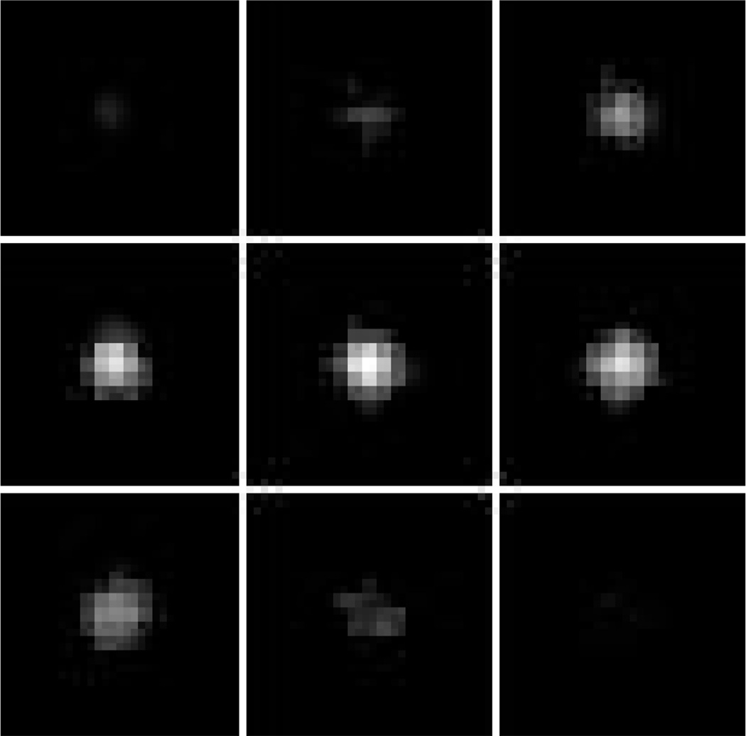
In order to utilize the thicker scintillation crystal optimally, and to take advantage of the increased sensitivity that would result from placing such a detector next to the subject, estimating depth of interaction will be imperative. Otherwise resolution loss due to parallax would certainly occur. In our position- estimation scheme, this would require full knowledge of the PMT mean values as a function of (x, y, z) scintillation position. We have developed both new calibration methods and new computer-modeling methods for obtaining the p̄i (x, y, z) (Eq. 1) and have begun to test them. Simulation experiments have been conducted that predict a very good resolution in depth, (z), and excellent (x, y) resolution if all three parameters are estimated. Monte Carlo results are given in Fig. 4 for 5,000 photons striking the detector at the same (x, y, z) position, with the different planes representing 1mm increments in depth.
Fig. 4.
Monte Carlo results showing expected 3D scintillation-camera resolution. each slice represents 1mm in depth.
Other areas that we have begun to explore or will explore include using four cameras for better angular sampling (it is possible that some effects of incomplete angular sampling are seen in Fig. 3(b), new scintillators such as LaBr3(Ce) and LaCl3(Ce) for better light output, PSPMTs in place of single-anode PMTs, and the use of these modular cameras in place of block detectors in more traditional PET systems. We conclude that this new PET system offers a promising alternative to block/segmented detectors, and that future advances will allow even better performance.
Contributor Information
Donald W. Wilson, Email: dwwilson@radiology.arizona.edu, Department of Radiology, The University of Arizona, Tucson, Arizona 85724.
Lars R. Furenlid, Department of Radiology, and Optical Sciences Center, Tucson, Arizona 85724
Harrison H. Barrett, Department of Radiology, and Optical Sciences Center, Tucson, Arizona 85724
Yi Chun Chen, Optical Sciences Center, The University of Arizona, Tucson, Arizona 85721.
References
- 1.Cherry SR, Shao Y, Siegel S, Silverman RW, Mumcuoglu E, Meadors K, Phelps ME. Optical fiber readout of scintillator arrays using a multi-channel PMT: A high resolution PET detector for animal imaging. IEEE Trans. Nucl. Sci. 1997;44:1161–1166. [Google Scholar]
- 2.Cherry SR, Shao Y, Silverman RW, Meadors K, Siegel S, Chatziioannou A, Young JW, Jones WF, Moyers JC, Newport D, Boutefnouchet A, Farquhar TH, Andreaco M, Paulus MJ, Binkley DM, Nutt R, Phelps ME. MicroPET: A high resolution PET scanner for imaging small animals. IEEE Trans. Nucl. Sci. 1997;44:1161–1166. [Google Scholar]
- 3.Joung J, Miyaoka RS, Lewellen TK. cMiCE: a high resolution animal PET using continuous LSO with a statistics based positioning scheme. Nuc. Inst. and Meth. in Phys. Res. A. 2002;489:584–598. [Google Scholar]
- 4.Auffray E, Buyndoncks P, Devroede O, et al. The ClearPET project of scintillator arrays using a multi-channel. Nucl. Inst. and Meth. in Phys. Res. Section A. 2004;527:171–174. [Google Scholar]
- 5.Di Domenico G, Motta A, Zavattini G, Del Guerra A, Damiani C, Bettinardi V, Cilardi MC. Characterization of the Ferrara animal PET scanner. Nucl. Inst. and Meth. in Phys. Res. Section A. 2002;477:505–505. [Google Scholar]
- 6.Surti S, Karp JS, Perkins AE, Freifelder R, Muehllehner G. Design evaluation of A-PET: A high sensitivity animal PET camera. IEEE Trans. Nucl. Sci. 2003;50:1357–1363. [Google Scholar]
- 7.Burnham CA, Kaufman D, Fischman AJ. Development of a small animal PET imaging device with resolution approaching 1mm. IEEE Trans. Nucl. Sci. 1999;46:631–635. [Google Scholar]
- 8.Jarritt PH, Acton PD. PET imaging using gamma camera systems: a review. Nuc. Med. Communications. 1996;17:758–766. doi: 10.1097/00006231-199609000-00006. [DOI] [PubMed] [Google Scholar]
- 9.Lewellen TK, Miyaoka RS, Swan WL. PET imaging using dual-headed cameras: an update. Nuc. Med. Communications. 1999;20:5–12. doi: 10.1097/00006231-199901000-00003. [DOI] [PubMed] [Google Scholar]
- 10.Kiukka JT, Sohlberg A, Husso-Saastamoinen M. PET imaging using a triple-head gamma camera. Clin. Physiol. and Func. Im. 2002;22:328–331. doi: 10.1046/j.1475-097x.2002.00439.x. [DOI] [PubMed] [Google Scholar]
- 11.D’Asseler Y, Vandenberghe S, DeWinter F, Van de Walle R, Koole M, Bouwens L, Lamahieu I, Dierckx RA. PET imaging using gamma cameras. Comp. Med. Imag. and Graphics. 2001;25:87–96. doi: 10.1016/s0895-6111(00)00058-6. [DOI] [PubMed] [Google Scholar]
- 12.Freifelder R, Karp JS, Geagan M, Muehllehner G. Design and performance of the head PENN-PET scanner. IEEE. Trans. Nucl. Sci. 1994;41:1436–1440. [Google Scholar]
- 13.Siegel S, Cherry SR, Ricci AR, Shao Y, Phelps ME. Development of continuous detectors for high resolution PET system. IEEE Trans. Nucl. Sci. 1995;42:1069–1074. [Google Scholar]
- 14.LeBlanc JW, Thompson RA. A novel PET detector block with three-dimensional hit positioning. IEEE Trans. Nucl. Sci. 2004;51:746–751. [Google Scholar]
- 15.Seidel J, Gandler WR, Green MV. Characteristics of a pair of small field-of-view LSO scintillation cameras. IEEE Trans. Nucl. Sci. 1996;43:1968–1973. [Google Scholar]
- 16.Furenlid LR, Wilson DW, Chen YC, Kim H, Pietraski PJ, Crawford MJ, Barrett HH. FastSPECT II: A second-generation high-resolution dynamic SPECT imager. IEEE Trans. Nucl. Sci. 2004;51:631–635. doi: 10.1109/TNS.2004.830975. [DOI] [PMC free article] [PubMed] [Google Scholar]
- 17.Barrett HH, Myers K. Foundations of Image Science. Wiley; 2004. [Google Scholar]
- 18.Dorenbos P, de Haas JTM, van Eijk CWE. Non-proportionality in the scintillation response and the energy resolution obtainable with scintillation crystals. IEEE Trans. Nucl. Sci. 1995;42:2190–2212. [Google Scholar]


