Abstract
We developed a miniature quantitative optical coherence elastography (qOCE) instrument with an integrated Fabry-Perot force sensor, for in situ elasticity measurement of biological tissue. The technique has great potential for biomechanics modeling and clinical diagnosis. We designed the fiber-optic qOCE probe that was used to exert a compressive force to deform tissue at the tip of the probe. Using the space-division multiplexed optical coherence tomography (OCT) signal detected by a spectral domain OCT engine, we were able to quantify the probe deformation that was proportional to the force applied, and to quantify the tissue deformation corresponding to the external stimulus. Simultaneous measurement of force and displacement allowed us to extract Young’s modulus of biological tissue. We experimentally calibrated our qOCE instrument, and validated its effectiveness on tissue mimicking phantoms and biological tissues.
OCIS codes: (170.4500) Optical coherence tomography, (280.4788) Optical sensing and sensors, (280.3340) Laser Doppler velocimetry
1. Introduction
Optical coherence tomography (OCT) is a versatile, high-resolution imaging technique, with great potential in tissue characterization for various biomedical applications such as cancer diagnosis or surgical guidance [1, 2]. In addition to structural imaging, OCT can also be used to perform mechanical characterization of biological tissue with one of its functional extensions referred as optical coherence elastography (OCE) [3–10]. OCE can quantify mechanical response (deformation, resonant frequency, elastic wave propagation) of biological tissues under external or internal mechanical stimulation, and extract tissue properties related to its pathological and physiological status. For example, pathological tissue such as cancerous tissue is usually stiffer compared to normal tissue, in addition to structural abnormity [11, 12]. This tissue stiffening is exactly a clinician looks for when he/she manually palpitates the tissue for changes in mechanical properties. Compared to elastography techniques based on ultrasound or MRI, OCE has advantages in spatial resolution, mechanical sensitivity, and imaging speed.
Various OCE techniques have been developed to date including compression OCE, surface acoustic wave OCE (SAW OCE), and magnetomotive OCE (MM OCE) [13]. Compared to SAW OCE that has a spatial resolution in the order of millimeter and MM OCE that requires external contrast agent, compression OCE provides the highest spatial resolution for elastography and is based on intrinsic mechanical changes during compression [14–19]. On the other hand, recently developed fiber optic probes allowed endoscopic OCT imaging/sensing despite small penetration depth of OCT signal [20–23]. Needle OCE has been used to measure mechanical response from deep tissue [10]. Therefore, compression OCE based on a miniature fiber optic probe has a great potential for in situ characterization of mechanical properties of biological tissue. However, conventional compression OCE measures tissue displacement under quasi-static compression and does not quantify mechanical loading, unless the state of stress is established through an inverse elastic or viscoelastic solution to the boundary value problem. For quantitative characterization of tissue stiffness, current compressive OCE technique has limited significance because results obtained from different compression OCE measurement sessions are qualitative and cannot be correlated in longitudinal or comparison studies.
To obtain quantitative measurements of tissue elasticity, we proposed a novel quantitative optical coherence elastography (qOCE) technology that measures tissue elasticity using a miniature probe with integrated force sensing functionality [24–26]. The qOCE system developed in this study is significantly different from its predecessors, because it simultaneously measures the force/stress exerted on the tissue and the resultant tissue deformation/strain. In addition, the miniature probe can access deep tissues of interest at multiple locations required for clinical applications, for such variations lead to different biochemical pathways and hence different medical outcomes. In a word, qOCE has great potential in interstitial imaging/sensing for in situ tissue mechanical characterization.
In this study, we designed and fabricated the qOCE probe with an integrated Fabry-Perot (FP) cavity to quantify the force exerted at the probe tip. A spectral domain OCT engine at 1.3 μm was used to detect space-division multiplexed signal for simultaneous force and displacement (stress and strain) measurement. Signal processing was implemented in real-time using graphic processing units (GPU). We characterized the performance of our qOCE instrument, and validated its effectiveness on tissue mimicking phantoms as well as biological tissues.
The manuscript is organized as follows. We first illustrated the principle of qOCE technology and the system configuration. Then we showed the experiment results obtained with our qOCE setup, including calibration for deformation and force tracking, stress-strain curve acquisition, and measurements on three phantoms with different values of stiffness. Finally we presented qOCE measurement results obtained from biological tissue.
2. Principle of qOCE technology
2. 1 System configuration
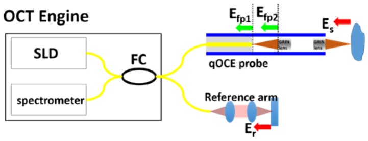
The system schematic is shown in Fig. 1. Broadband output from a super luminescent diode (SLD) is routed by a fiber optic coupler (FC) to the qOCE probe and the reference arm. A miniature probe (qOCE probe) is used to induce compression in the sample. If the sample is mechanically homogeneous, the loading produces uniaxial compression. Otherwise, the state of stress is determined by the heterogeneity that can also be measured. To track probe deformation in response to the applied force, a common path OCT signal is detected. The common path OCT signal is derived from the interference from optical fields reflected from the tip of single mode fiber (Efp1) and from the first surface of the GRIN (gradient index) lens (Efp2). Another OCT signal derived from the interference between sample light (Es) and reference light (Er) through Michelson interferometry is used to track sample deformation in front of the probe tip.
Fig. 1.
Illustration of qOCE system (FC: fiber optic coupler; SLD: superluminescent diode; Efp1, optical reflection from the tip of single mode fiber; Efp2, optical reflection from the proximal end of the first GRIN lens; Es, sample light; Er, reference light.
As shown in Fig. 1, a lead-in single mode fiber (SMF) is attached to the proximal end of the qOCE probe shaft and a pair of GRIN lenses is attached to the distal end of the probe shaft. The cleaved SMF tip and the proximal surface of the first GRIN lens serve as two end surfaces of a low fineness Fabry Perot (FP) cavity. Incident light from the SLD is reflected by two end surfaces (Efp1 and Efp2) of the FP cavity due to a discontinuity in refractive index (from glass to air and from air to glass). The common path interference between Efp1 and Efp2 generates an OCT signal (Ascan, Ip) with a peak located at the depth Lfp that equals the FP cavity length. The phase of complex valued OCT signal at Lfp changes in proportion to the change in FP cavity length and thus the force exerted at the probe tip. Therefore, tracking Doppler phase shift of the common path OCT signal allows the quantification of probe deformation and force/stress exerted through the probe. On the other hand, the GRIN lens pair also functions as an objective lens to focus the light output from SMF for sample illumination. The backscattered light from the sample (Es) is collected by the fiber optic probe and detected by the spectrometer for OCT imaging. Es interferes with reference light (Er) provided by the reference arm and generates depth profile of the sample. It is worth mentioning that we adjust the optical path length of reference arm, so that OCT signal from the sample (Is) starts beyond Lfp. Optical path length is matched by a single model fiber patch cord in reference arm and through coarse and fine adjustment of the position of the collimator in reference arm. This configuration allows spatial division multiplexing of the OCT signal for simultaneous probe deformation (ΔLprobe) tracking and tissue deformation (ΔLsample) tracking. Notably, the compound lens (a pair of GRIN lenses) allows light beam to be tightly focused into sample and Lfp to be small. A shorter FP cavity length allows Is to be located closer to the equal optical path plane with insignificant signal roll-off. Denote the optical path length (OPL) of light reflected by the distal surface of the second GRIN lens as LGRIN. By choosing the OPL of the reference arm (Lref) to be smaller than LGRIN + Lfp, sample can be located beyond Lfp to eliminate overlap with signal from the FP cavity. If the material of the specimen (phantom or tissue) is linearly elastic, a static force yields a uniform displacement. If the material is viscoelastic, a dynamic sinusoidal force can be applied and the response measured. Since the mechanical property of the specimen is unknown, a simplified linear elastic model with a Young’s modulus E is assumed in this study.
Using OCT signals obtained, we can quantify probe deformation ΔLprobe and derive the force exerted: F = αΔLprobe where α is a constant determined by the mechanical property of the probe and will be characterized through calibration experiments. We then quantify the stress applied to sample: σ = F/A where A is the area of the GRIN lens. In addition, we can calculate tissue strain ε = ΔLsample/L0. Here, L0 is the initial specimen thickness before compression. Finally, the sample’s Young’s modulus (E) that is the linear slope of strain-stress curve can be obtained using Eq. (1) where tissue elasticity can be quantified by comparing the deformation of probe and sample.
| (1) |
Notably, Eq. (1) is valid based on the following assumptions. First, the load is applied slowly. Therefore, force applied to tissue is equivalent to force measured by the integrated Fabry Perot force sensor. Second, the tissue specimen is elastic and viscoelasticity is not considered. Third, the materials are not compressible and therefore have a Poisson’s ratio of 0.5.
In this study the elastic tissue specimen is sandwiched by two rigid compressors one of which is the qOCE probe tip. This configuration can provide the most simplified boundary condition and is equivalent to indentation measurement frequently used to characterize biomechanical properties of soft tissue. For example, indentation measurement on Young’s moduli of breast tissues was performed through simultaneous quantification of mechanical loading and tissue deformation [12, 31]. Quantification of elasticity was also performed using OCT in a similar compression OCE setting [32].
2.2 Signal processing
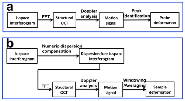
For quantitative mechanical property measurement, we first perform DC subtraction and interpolation on spectral domain OCT data acquired by the CMOS camera to obtain k (wavenumber) space interferogram. Afterwards, Doppler analysis is performed to track probe and sample deformation. As shown in Fig. 2, slight different processing is applied to track probe deformation and sample deformation.
Fig. 2.
(a) Signal processing for probe deformation tracking for the quantification of force/stress; (b) signal processing for tissue deformation tracking for the quantification of deformation/strain.
To track probe deformation (Fig. 2(a)), we simply apply fast Fourier transform (FFT) on k space interferogram to obtain a complex valued 1D OCT signal Ip(z,t). Here z indicates axial coordinate and t indicates measurement time. We then identify the signal peak generated by the interference between optical waves from two end surfaces of the FP cavity: Ip(Lprobe, t). Doppler phase shift ((δϕprobe(t))) between Ascans acquired at different time with interval δtp (δtp = 5 ms) is calculated according to Eq. (2) [27]. δϕprobe(t) is proportional to probe deformation and thus the force applied.
| (2) |
Sample deformation tracking is extracted from OCT signal from the sample (Is(z,t)), also through Doppler analysis (Fig. 2(b)). Notably, signal processing to track sample deformation is slightly different from probe deformation tracking. First, as shown in Fig. 1, OCT signal from the sample derives from light interference between probe arm and reference arm; therefore suffers from signal degradation due to considerable amount of chromatic dispersion. To obtain high resolution, high signal to noise ratio OCT signal Is(z,t) from the sample, we measure the amount of dispersion mismatch in prior. The non-linear phase of the interferometric spectrum is extracted through Hilbert transformation on interferometric spectrum. Third order polynomial fitting is applied to approximate the non-linear phase: Φ(k) = p3k3 + p2k2 + p1k + p0. The non-linear phase is then subtracted in the GPU based software before FFT for real-time dispersion compensation. Second, biological tissue is less rigid compared to the plastic probe shaft and deforms more. Therefore, we will use two Ascans acquired with smaller time interval (δts = 0.2 ms) for Doppler phase calculation (Eq. (3)). Otherwise, deformation obtained through Doppler analysis may suffer from phase wrapping artifact. Third, structural OCT signal from highly scattering sample is inevitably contaminated by speckle noise and so is Doppler OCT signal. To track sample deformation with higher accuracy, we will perform spatial average to obtain filtered phase shift (δϕsample,filtered(t)) for better accuracy (Eq. (4)). δϕsample,filtered(t) is proportional to spatially resolved displacement of the sample that can be converted to local deformation and strain.
| (3) |
| (4) |
with δϕprobe(t) or δϕsample,filtered(t) obtained, probe deformation (δLprobe) and sample deformation (δLsample) can be calculated according to Eq. (5). For probe deformation tracking, the central wavelength of SLD output in air (λ0 = 1.3μm) is used in Eq. (5). For sample deformation tracking, the wavelength is corrected by the refractive index (λ = λ0/n).
| (5) |
Notably, in compression OCE, mechanical loading is applied to tissue in a quasi-static process and it is essential to quantify deformation over the entire course of compression. Therefor, deformation of probe and sample are both integrated over the same time interval, as shown in Eq. (6). The time integration also improves signal to noise ration for elasticity measurement.
| (6) |
with probe and sample deformation acquired using Eq. (5) and (6), we are able to quantify tissue elasticity using Eq. (1). In the real-time software, a variable is constantly updated to calculate the accumulated displacement: ΔLprobe,sample = ΔLprobe,sample + dLprobe,sample, where dLprobe,sample is the incremental displacement. Signal processing for deformation tracking and elasticity sensing is implemented in real-time using graphic processing unit (GPU).
3. Results
3.1 qOCE system and signal characteristics
The qOCE system is based on a 1.3 μm spectral domain OCT engine that tracks both probe and sample deformation. The SD OCT engine was described in detail in our previous publications [28]. Briefly, a superluminescent diode (SLD1325 Thorlabs, 100nm bandwidth, corresponding to a 7.4 μm axial resolution) is used as light source and interference signal is detected by a CMOS InGaAs camera (SUI1024LDH2, Goodrich).
According to the design described in 2.1, we developed a qOCE probe as shown in comparison with a US quarter in Fig. 3. To fabricate the probe, we first inserted a single mode fiber into a 25-gauge stainless steel tube. The fiber and the tube were glued together with optical epoxy to achieve desired rigidity for elasticity measurement. With additional cascaded tubing, the fiber was integrated with a polyimide tube (Microlumen) with 1.8mm inner diameter. Optical epoxy was applied to the proximal end of the polyimide tube for fixation. A pair of GRIN lenses (Newport, LGI1300-1A, 0.23 pitch, 0.26 mm working distance) was attached to the distal end of the polyimide tube. The distance between the first GRIN lens and fiber tip was adjusted to collimate the light beam. The second GRIN lens was used to focus the light beam so that the waist of the output beam was located at a depth 0.26 mm away from the GRIN lens surface. Notably, the mechanically active segment for OCT sensing in this probe is the segment between the fixation points of the SMF and the first GRIN lens.
Fig. 3.
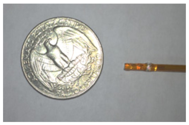
Photo of qOCE probe in comparison with a US quarter.
Typical Ascan signals obtained from the qOCE probe are shown in Fig. 4. Figure 4(a) shows OCT signals obtained from the probe without (black) and with (blue) numeric dispersion compensation. The sample was a silicone phantom that used Titanium dioxide to provide light scattering. Both Ascans multiplex signals from the common path interferometer and the Michelson interferometer. For the Ascan obtained without dispersion compensation (black), a sharp signal peak (red arrow) is observed. This peak corresponds to common path OCT signal derived from the FP cavity (interference between optical fields Efp1 and Efp2 in Fig. 1). As Efp1 and Efp2 share the same optical path, the interferometric signal is free of dispersion mismatch and a sharp peak is obtained without dispersion compensation. On the other hand, this Ascan shows broadened signal at a larger imaging depth, as indicated by the dashed rectangle. Signal enclosed by the rectangle derives from the interference between the reference mirror (Er) and the distal surfaces of the second GRIN lens (EGRIN), as well as specimen (Es) under imaging. Reference light and sample light in the Michelson interferometer travels in different medium (fiber and air). Therefore, considerable signal degradation is observed because of dispersion mismatch. In comparison, the blue curve in Fig. 4(a) obtained after dispersion compensation shows a sharp peak corresponding to the distal surface of the GRIN lens (indicated by the green arrow), a sharp peak corresponding to the sample surface (indicated by the orange arrow) and depth resolved sample profile. However, OCT signal due to interference between Efp1 and Efp2 diminishes in the blue curve because of additional non-linear phase induced to dispersion-free signal in the process of numerical dispersion compensation. Figure 4(a) clearly shows that OCT signal from the Fabry-Perot cavity for force/stress measurement is spatially demultiplexed with OCT signal from tissue for displacement/strain measurement. We multiplexed CP OCT signal obtained from the FP cavity without dispersion compensation, and Michelson OCT signal obtained from tissue with dispersion compensation and show the result in Fig. 4(b). By tracking phase shift between complex valued, spatial division multiplexed OCT signal as shown in Fig. 4(b), we were able to quantify probe and tissue deformation. Figure 4(c) shows segments of OCT signal obtained from the Michelson interferometer after dispersion compensation, with weakly scattering phantom as sample. Curves with different color were obtained when the sample was located at different depths. Signal peak derived from the GRIN lens surface (indicated by the green arrow) remains identical for different signals. Notably, focusing effect can be observed in Fig. 4(c) with focal plane approximately 0.26mm away from the GRIN lens surface.
Fig. 4.
(a) Typical Ascan obtained from the probe without (black) and with (blue) dispersion compensation; (b) multiplexed signal for simultaneous probe and tissue deformation tracking; (c) segments of OCT signal obtained from Michelson interferometry after dispersion compensation, with weakly scattered sample located at different depth.
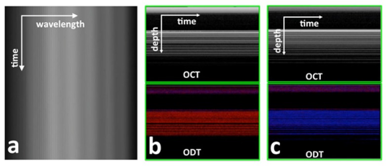
To track probe and tissue deformation, we quantified temporal variation of Ascan in Doppler phase shift as shown in Fig. 5. Figure 5(a) (Visualization 1 (904.2KB, MP4) ) shows a frame of sequentially acquired spectral interferograms. In Fig. 5(a), different coordinate in horizontal direction corresponds to different wavelength/wavenumber and different coordinate in vertical corresponds to different time. Fringes due to the interference between optical fields from the two end surfaces of the FP cavity are visible in Fig. 5(a). As the probe was used to compress tissue during the acquisition of Fig. 5(a), slight fringe shift over time can be observed due to probe shaft deformation. Fringe shift can be seen more clearly in Visualization 1 (904.2KB, MP4) . Using our real-time GPU software, we quantified the phase shift shown in Fig. 5(a) and Visualization 1 (904.2KB, MP4) using Eq. (2) and converted the phase shift to probe deformation using Eq. (4) and (5). Figure 5(b) (Visualization 2 (2.6MB, MP4) ) shows signal from tissue (screen capture of real-time display) when the qOCE probe was used to compress the phantom. Our software showed structural OCT signal (uppper), as well as Doppler OCT signal (ODT, lower) obtained by calculating inter Ascan signal phase shift. Sequentially acquired signals are displayed in Fig. 5(b) where different coordinate in horizontal direction corresponds to different time and different coordinate in vertical direction corresponds to different depth. Similarly, Fig. 5(c) (Visualization 3 (2.2MB, MP4) ) is the screen capture of real-time display when releasing the compression exerted to the same phantom through the probe. Notably, in our software, the color of Doppler signal was used to identify the direction of the motion or phase shift. The negative phase shift was coded to be red and the positive phase shift was coded to be blue. Due to small time window (0.1s) for the acquisition of Ascans during quasi-static compression shown in Fig. 5(b) and 5(c), phantom deformation was small and could not be observed in structural OCT images (upper insets of Fig. 5(a) and 5(b)). However, the phase of OCT signal provides much higher sensitivity in deformation tracking. Deformation of phantom in different direction due to compression and removal of compression could be clearly observed in the lower panels of Fig. 5(b) and 5(c).
Fig. 5.
(a) A frame of interferometric spectrum obtained when the probe was used to exert force (Visualization 1 (904.2KB, MP4) ); (b) structural OCT image (upper) and Doppler OCT image (lower) obtained when the phantom was compressed by the qOCE probe (Visualization 2 (2.6MB, MP4) ); (b) structural OCT image (upper) and Doppler OCT image (lower) obtained when the compression was released (Visualization 3 (2.2MB, MP4) ).
3.2. qOCE probe calibration
Accurate characterization of elastic property of tissue depends on accurate measurement of externally applied force/stress and the tissue’s response in the form of deformation/strain.
First, we calibrated the accuracy of deformation/displacement tracking experimentally. We attached the qOCE probe to a precise linear motor (Newport, ILS100CC DC). The probe was translated by the motor in axial direction and did not touch the rigid scattering sample. Therefore, the displacement between the probe and the sample was equivalent to the distance translated by the motor. Using OCT signal, we calculated displacement between qOCE probe and sample according to Eqs. (3)–(6), in our real-time GPU software. Displacement extracted through Doppler analysis of OCT signal was compared with the known motor displacement, as shown in Fig. 6. Clearly, displacement calculated using Doppler analysis has a linear dependency on actual displacement. We validated the following model Dphysical = aDDoppler + b using linear regression, and our results indicated a = 1.2 and b = 0.004mm. R2 statistic of the fitting is 0.9977, indicating a highly linear relationship between the calculated displacement and the actual displacement. The coefficient a accounts for the direction of light propagation traveling and the refractive index of the phantom.
Fig. 6.
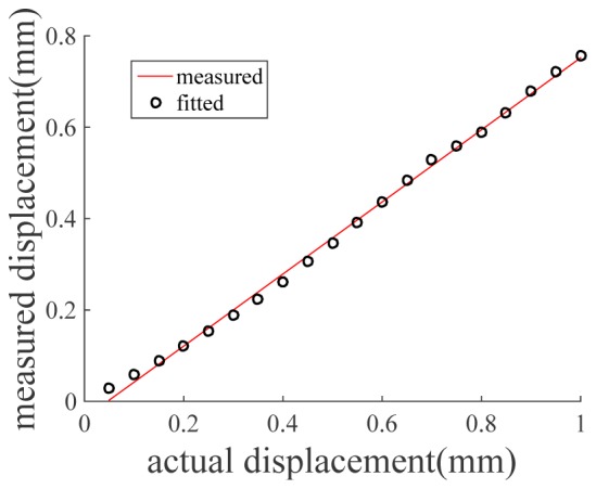
Calibration results show displacement obtained from Doppler OCT signal is linearly related to actual displacement.
In addition, we calibrated the force/stress sensing capability of our qOCE system. We mounted the qOCE probe on a linear stage and translated the stage to exert force to the sensing tip of a digital force gauge (Shimpo, FG-3005) that provided high precision force measurement with 0.005 N resolution. We tracked the probe deformation using Doppler OCT signal obtained from the integrated FP cavity and compared the probe deformation with force exerted, as shown in Fig. 7. Clearly, the length of FP cavity varied linearly as the force. We validated the following model DFPC = αF + β using linear regression, and our results indicated α = 0.1795N/μm. R2 statistic of the fitting is 0.9971, indicating a highly linear relationship between the force and the probe deformation.
Fig. 7.
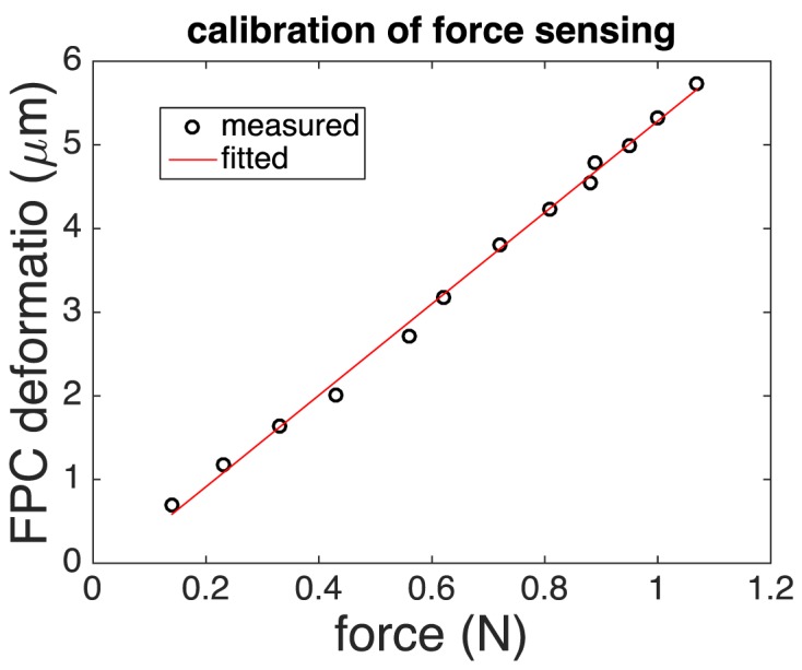
Results of force calibration show FP cavity deforms proportionally to force exerted.
Figure 6 and Fig. 7 illustrate that the force and displacement can be quantified using OCT signal. Based on results obtained from the calibration experiments, we were able to convert phase shift extracted from OCT signal to tissue deformation and force. Stress was then calculated using the area of the GRIN lens (~2.54 mm2) in contact with sample for compression.
3.3. Elasticity measurement using qOCE
We developed phantoms to evaluate the qOCE technique. We choose silicone based phantom because the elastic modulus of silicone phantom can be varied in a range that well overlaps the elastic modulus of biological tissues and the optical property of silicone phantom in terms of refractive index is close to that of biological tissues. To obtain phantom with different stiffness, we combine polydimethylsiloxane (PDMS) fluid with curing agent at different volumetric ratios. In addition, we add titanium dioxide into silicone to provide light scattering [29].
To validate that our qOCE can simultaneously quantify stress and strain for elasticity measurement, we used the qOCE probe to compress an elastic phantom. Stress was obtained in real-time, using FP cavity deformation extracted from Doppler phase shift between OCT Ascans, calibrated force-deformation relationship, and known GRIN lens dimension. On the other hand, phantom strain was obtained in real-time, using OCT signal within a window (approximately 280 μm width) located in the vicinity of beam waist (approximately 260 μm from the surface of the second GRIN lens). Tissue deformation was obtained by averaging displacement signal obtained through Doppler analysis within the window and corrected by the refractive index of silicone phantom (n = 1.4). Strain was then calculated by dividing the deformation at each depth position and then averaged. We recorded stress and strain values during the compression of the probe, shown as the black curve in Fig. 8. In addition, we repeated the strain stress measurement, quantifying the force/stress with the commercial force gauge and quantifying the deformation/strain with the accurate linear translation stage. The results obtained are shown in Fig. 8 as the red curve that is highly consistent with qOCE measurement. Phantom elasticity was then obtained according to stress-strain curves shown in Fig. 8. The red curve results in an elasticity modulus that is 2.09 MPa and the black curve results in an elasticity modulus that is 2.02 MPa, indicating high accuracy qOCE measurement of tissue elasticity.
Fig. 8.
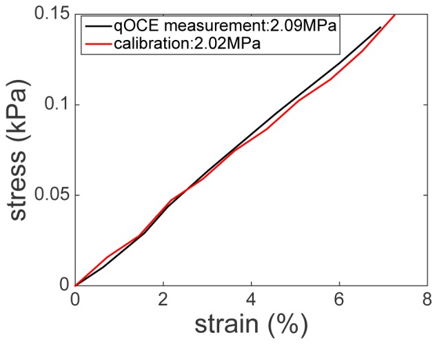
Stress-strain curve obtained using qOCE measurement (black) and calibration of strain-stress curve (red).
To demonstrate that the qOCE technique developed in this study can be used to differentiate sample with different stiffness, we fabricated three PDMS phantoms to have different elastic moduli and performed qOCE measurement. Our real-time software tracked probe and sample deformation using OCT signal, and used Eq. (1) to calculated sample elasticity moduli. Results are shown in Table 1. In addition, we performed calibration experiments for elasticity measurement, shown as the second row of Table 1. In these calibration experiments, we measured force/stress using the force gauge and we obtained deformation/strain according to the reading of the linear stage. Table 1 indicates qOCE can provide reliable elasticity measurement.
Table 1. Elasticity measurement on phantom.
| Young’s modulus | Phantom1 | Phantom2 | Phantom3 |
|---|---|---|---|
| qOCE measurement (MPa) | 0.72 | 0.99 | 2.51 |
| Calibration (MPa) | 0.69 | 0.94 | 2.45 |
We further validated qOCE technique on biological tissue, by measuring different tissues from chicken (ex vivo). We compared the elasticity of fat, muscle and heart of chicken. The Young’s moduli obtained using qOCE are shown in Table 2. We can see the difference in stiffness between different tissues, suggesting our qOCE technique has the potential in distinguishing cancer tissue from normal tissue. However, it is challenging to correlate results shown in Table 2 with values of Young’s moduli reported in literature. This is because reliable data on Young’s moduli of soft tissue are very limited and available values tend to be inconsistent. A review study indicated that measured Young’s moduli for any given tissue usually span several orders of magnitude [31]. For example, the Young’s modulus of breast tissue has an average value of ~7kPa when measured by atomic force microscopy (AMF) but has an average value of ~480Mpa when measured by tensile stretching. Notably, Young’s moduli obtained from qOCE measurement are generally larger than values obtained from AFM and smaller than values obtained through tensile stretching. This may be due to the tissue volume that qOCE characterizes is larger than the one in AFM measurement and smaller than the one in tensile stretching measurement.
Table 2. Elastic property measurement on chicken tissues.
| Fat | Muscle | Heart | |
|---|---|---|---|
| Young’s modulus (Mpa) | 0.21 | 0.63 | 7 |
Conclusion and discussion
To conclude, we demonstrated and validated to our knowledge the first time fiber-optic quantitative optical coherence elastography (qOCE) device, which simultaneously quantifies force exerted on the tissue and measures the resultant tissue deformation. The qOCE technique allows direct measurement of elastic properties and therefore has great potential in many applications, such as cancer diagnosis, brain injury study, tissue engineering and biomechanical modeling.
Currently, Young’s modulus can be obtained from atomic force microscopy that studies tissue mechanics at the micro- through nanoscopic scale, or be obtained from tensile stretching or indentation measurement that studies tissue mechanics at the macroscopic scale [30]. However, these techniques rely on ex vivo tissue specimens that have different mechanical properties of tissue in living organism. Therefore, the proposed qOCE technique that allows in situ measurement of Young’s modulus is highly significant for the study of tissue mechanics.
The axial resolution of qOCE was limited by the axial resolution (7.4μm) of OCT imaging. and the lateral resolution of qOCE was determined by optical confinement of light beam incident into sample. In principle, the qOCE technique developed in this study allowed spatially resolved characterization of mechanical property. However, the focus of this study was the quantification of elasticity modulus. Therefore, phantom with homogeneous mechanical property was tested using qOCE and spatial resolution for elastography was not the major concern.
The accuracy of qOCE measurement depends on the effectiveness of Doppler phase analysis in the quantification of force and sample deformation. The minimal displacement between Ascans that could be tracked using Doppler phase shift in the current OCT system was approximately 0.1nm, determined by random phase noise [26]. The maximum displacement between Ascans that could be tracked using Doppler phase shift in the current OCT system was approximately 325nm, limited by the range free of phase wrapping artifacts. In this study, we strategically chose the time interval between Ascans involved in Doppler phase calculation, to track phase shift during the process of quasi-static compression. The sensitivity of our device in force measurement could be higher than 0.25mN and the maximum force we applied through the qOCE probe was approximately 1N. The instrument is limited by the time derivative of force (dF/dt). Doppler analysis of OCT signal essentially quantifies the change of force (dF) within a small time interval (dt). Force is then obtained by integrating dF over time. The accuracy of force measurement is compromised, when dF is large and results in phase wrapping artifacts in Doppler OCT signal. Based on the stiffness of the probe shaft and the imaging speed of our OCT system, the system can theoretically quantify force with a 12,000 N/s derivative. It is possible to adaptively choose Ascans for Doppler phase analysis to improve the robustness in deformation tracking, in a way similar to adaptive speckle tracking method we developed before for lateral motion tracking [28].
We used a polyimide tube as qOCE probe shaft and assumed it deforms proportionally to force applied. The assumption was validated in experimental results shown in Fig. 7. Alternatively, we may use superelastic Nitinol that returns to its original shape when loading is released as the material for qOCE probe shaft.
We performed qOCE measurement to extract Young’s modulus (Elasticity modulus) of sample. However, almost all of biological tissues are viscoelastic rather than elastic and therefore exhibit time-dependent strain under mechanical loading. Nevertheless, the elastic model for biological tissue is usually valid for small strain (<10%) under quasi-static mechanical loading. In fact, incremental sample deformation and probe deformation (δLsample and δLprobe) were quantified over the entire process of compression of qOCE measurement, as shown (Eq. (5)). Although only two values, accumulated sample deformation and probe deformation (ΔLsample and ΔLprobe) were involved in elasticity calculation, the qOCE technique developed in this study has the capability to track the temporal profile of deformation with mechanical stimulation to fully characterize viscoelasticity of biological tissue.
Acknowledgment
The research reported in this manuscript is supported by internal funding from New Jersey Institute of Technology.
References and links
- 1.Fujimoto J. G., Pitris C., Boppart S. A., Brezinski M. E., “Optical Coherence Tomography: An Emerging Technology for Biomedical Imaging and Optical Biopsy,” Neoplasia 2(1-2), 9–25 (2000). 10.1038/sj.neo.7900071 [DOI] [PMC free article] [PubMed] [Google Scholar]
- 2.Izatt J. A., Kulkarni M. D., Kobayashi K., Sivak M. V., Barton J. K., Welch A. J., “Optical coherence tomography for biodiagnostics,” Opt. Photonics News 8(5), 41 (1997). 10.1364/OPN.8.5.000041 [DOI] [Google Scholar]
- 3.Schmitt J., “OCT elastography: imaging microscopic deformation and strain of tissue,” Opt. Express 3(6), 199–211 (1998). 10.1364/OE.3.000199 [DOI] [PubMed] [Google Scholar]
- 4.Wang R. K., Ma Z., Kirkpatrick S. J., “Tissue Doppler optical coherence elastography for real time strain rate and strain mapping of soft tissue,” Appl. Phys. Lett. 89(14), 144103 (2006). 10.1063/1.2357854 [DOI] [Google Scholar]
- 5.Wang R. K., Kirkpatrick S., Hinds M., “Phase-sensitive optical coherence elastography for mapping tissue microstrains in real time,” Appl. Phys. Lett. 90(16), 164105 (2007). 10.1063/1.2724920 [DOI] [Google Scholar]
- 6.Liang X., Boppart S. A., “Biomechanical Properties of In Vivo Human Skin From Dynamic Optical Coherence Elastography,” IEEE Trans. Biomed. Eng. 57(4), 953–959 (2010). 10.1109/TBME.2009.2033464 [DOI] [PMC free article] [PubMed] [Google Scholar]
- 7.Sun C., Standish B., Yang V. X. D., “Optical coherence elastography: current status and future applications,” J. Biomed. Opt. 16, 043001 (2011). [DOI] [PubMed] [Google Scholar]
- 8.Kennedy B. F., Liang X., Adie S. G., Gerstmann D. K., Quirk B. C., Boppart S. A., Sampson D. D., “In vivo three-dimensional optical coherence elastography,” Opt. Express 19(7), 6623–6634 (2011). 10.1364/OE.19.006623 [DOI] [PMC free article] [PubMed] [Google Scholar]
- 9.Nguyen T. M., Song S., Arnal B., Huang Z., O’Donnell M., Wang R. K., “Visualizing ultrasonically induced shear wave propagation using phase-sensitive optical coherence tomography for dynamic elastography,” Opt. Lett. 39(4), 838–841 (2014). 10.1364/OL.39.000838 [DOI] [PMC free article] [PubMed] [Google Scholar]
- 10.Kennedy K. M., Kennedy B. F., McLaughlin R. A., Sampson D. D., “Needle optical coherence elastography for tissue boundary detection,” Opt. Lett. 37(12), 2310–2312 (2012). 10.1364/OL.37.002310 [DOI] [PubMed] [Google Scholar]
- 11.McKnight A. L., Kugel J. L., Rossman P. J., Manduca A., Hartmann L. C., Ehman R. L., “MR elastography of breast cancer: preliminary results,” AJR Am. J. Roentgenol. 178(6), 1411–1417 (2002). 10.2214/ajr.178.6.1781411 [DOI] [PubMed] [Google Scholar]
- 12.Samani A., Zubovits J., Plewes D., “Elastic moduli of normal and pathological human breast tissues: an inversion-technique-based investigation of 169 samples,” Phys. Med. Biol. 52(6), 1565–1576 (2007). 10.1088/0031-9155/52/6/002 [DOI] [PubMed] [Google Scholar]
- 13.Kennedy B. F., Kennedy K. M., Sampson D. D., “A review of optical coherence elastography: fundamentals, techniques and prospects,” IEEE J. Sel. Top. Quantum Electron. 20(2), 272–288 (2014). 10.1109/JSTQE.2013.2291445 [DOI] [Google Scholar]
- 14.Kennedy B. F., Hillman T. R., McLaughlin R. A., Quirk B. C., Sampson D. D., “In vivo dynamic optical coherence elastography using a ring actuator,” Opt. Express 17(24), 21762–21772 (2009). 10.1364/OE.17.021762 [DOI] [PubMed] [Google Scholar]
- 15.Kennedy B. F., Koh S. H., McLaughlin R. A., Kennedy K. M., Munro P. R. T., Sampson D. D., “Strain estimation in phase-sensitive optical coherence elastography,” Biomed. Opt. Express 3(8), 1865–1879 (2012). 10.1364/BOE.3.001865 [DOI] [PMC free article] [PubMed] [Google Scholar]
- 16.Kennedy K. M., Ford C., Kennedy B. F., Bush M. B., Sampson D. D., “Analysis of mechanical contrast in optical coherence elastography,” J. Biomed. Opt. 18(12), 121508 (2013). 10.1117/1.JBO.18.12.121508 [DOI] [PubMed] [Google Scholar]
- 17.Li C., Guan G., Cheng X., Huang Z., Wang R. K., “Quantitative elastography provided by surface acoustic waves measured by phase-sensitive optical coherence tomography,” Opt. Lett. 37(4), 722–724 (2012). 10.1364/OL.37.000722 [DOI] [PubMed] [Google Scholar]
- 18.Mohan K. D., Oldenburg A. L., “Elastography of soft materials and tissues by holographic imaging of surface acoustic waves,” Opt. Express 20(17), 18887–18897 (2012). 10.1364/OE.20.018887 [DOI] [PubMed] [Google Scholar]
- 19.Crecea V., Oldenburg A. L., Liang X., Ralston T. S., Boppart S. A., “Magnetomotive nanoparticle transducers for optical rheology of viscoelastic materials,” Opt. Express 17(25), 23114–23122 (2009). 10.1364/OE.17.023114 [DOI] [PMC free article] [PubMed] [Google Scholar]
- 20.Mao Y., Chang S., Sherif S., Flueraru C., “Graded-index fiber lens proposed for ultrasmall probes used in biomedical imaging,” Appl. Opt. 46(23), 5887–5894 (2007). 10.1364/AO.46.005887 [DOI] [PubMed] [Google Scholar]
- 21.McLaughlin R. A., Quirk B. C., Curatolo A., Kirk R. W., Scolaro L., Lorenser D., Robbins P. D., Wood B. A., Saunders C. M., Sampson D. D., “Imaging of Breast Cancer With Optical Coherence Tomography Needle Probes: Feasibility and Initial Results,” IEEE J. Sel. Top. Quantum Electron. 18(3), 1184–1191 (2012). 10.1109/JSTQE.2011.2166757 [DOI] [Google Scholar]
- 22.Zhao M., Huang Y., Kang J. U., “Sapphire ball lens-based fiber probe for common-path optical coherence tomography and its applications in corneal and retinal imaging,” Opt. Lett. 37(23), 4835–4837 (2012). 10.1364/OL.37.004835 [DOI] [PMC free article] [PubMed] [Google Scholar]
- 23.Lorenser D., Yang X., Sampson D. D., “Ultrathin fiber probes with extended depth of focus for optical coherence tomography,” Opt. Lett. 37(10), 1616–1618 (2012). 10.1364/OL.37.001616 [DOI] [PubMed] [Google Scholar]
- 24.Zhang Y., Shibru H., Cooper K. L., Wang A., “Miniature fiber-optic multicavity Fabry-Perot interferometric biosensor,” Opt. Lett. 30(9), 1021–1023 (2005). 10.1364/OL.30.001021 [DOI] [PubMed] [Google Scholar]
- 25.Z. Sun, M. Balicki, J. Kang, J. Handa, R. Taylor, and I. Iordachita, “Development and preliminary data of novel integrated optical microforce sensing tools for retinal microsurgery,” in IEEE International Conference on Robotics and Automation, 2009. ICRA '09 (IEEE, 2009), pp. 1897–1902. [Google Scholar]
- 26.Liu X., Iordachita I. I., He X., Taylor R. H., Kang J. U., “Miniature fiber-optic force sensor based on low-coherence Fabry-Pérot interferometry for vitreoretinal microsurgery,” Biomed. Opt. Express 3(5), 1062–1076 (2012). 10.1364/BOE.3.001062 [DOI] [PMC free article] [PubMed] [Google Scholar]
- 27.Huang Y., Liu X., Kang J. U., “Real-time 3D and 4D Fourier domain Doppler optical coherence tomography based on dual graphics processing units,” Biomed. Opt. Express 3(9), 2162–2174 (2012). 10.1364/BOE.3.002162 [DOI] [PMC free article] [PubMed] [Google Scholar]
- 28.Wang Y., Wang Y., Akansu A., Belfield K. D., Hubbi B., Liu X., “Robust motion tracking based on adaptive speckle decorrelation analysis of OCT signal,” Biomed. Opt. Express 6(11), 4302–4316 (2015). 10.1364/BOE.6.004302 [DOI] [PMC free article] [PubMed] [Google Scholar]
- 29.Lamouche G., Kennedy B. F., Kennedy K. M., Bisaillon C. E., Curatolo A., Campbell G., Pazos V., Sampson D. D., “Review of tissue simulating phantoms with controllable optical, mechanical and structural properties for use in optical coherence tomography,” Biomed. Opt. Express 3(6), 1381–1398 (2012). 10.1364/BOE.3.001381 [DOI] [PMC free article] [PubMed] [Google Scholar]
- 30.McKee C. T., Last J. A., Russell P., Murphy C. J., “Indentation versus tensile measurements of Young’s modulus for soft biological tissues,” Tissue Eng. Part B Rev. 17(3), 155–164 (2011). 10.1089/ten.teb.2010.0520 [DOI] [PMC free article] [PubMed] [Google Scholar]
- 31.Kalanovic D. D., Ottensmeyer M. P., Gross J., Buess G., Dawson S. L., “Independent testing of soft tissue viscoelasticity using indentation and rotary shear deformations,” Stud. Health Technol. Inform. 94, 137–143 (2003). [PubMed] [Google Scholar]
- 32.Kennedy K. M., Chin L., McLaughlin R. A., Latham B., Saunders C. M., Sampson D. D., Kennedy B. F., “Quantitative micro-elastography: imaging of tissue elasticity using compression optical coherence elastography,” Sci. Rep. 5, 15538 (2015). 10.1038/srep15538 [DOI] [PMC free article] [PubMed] [Google Scholar]


