

Abstract
We report new experiments conducted using a camera phone wayfinding system, which is designed to guide a visually impaired user to machine-readable signs (such as barcodes) labeled with special color markers. These experiments specifically investigate search strategies of such users detecting, localizing and touching color markers that have been mounted in various ways in different environments: in a corridor (either flush with the wall or mounted perpendicular to it) or in a large room with obstacles between the user and the markers. The results show that visually impaired users are able to reliably find color markers in all the conditions that we tested, using search strategies that vary depending on the environment in which they are placed.
1. Introduction and previous work
Wayfinding in an unfamiliar environment is a difficult task for persons without sight. A number of techniques have been proposed or implemented to help blind and low vision individuals find their way, including Braille pads, GPS receivers, RFID tags and Talking Signs. Braille pads convey information in textual form (for persons who can read Braille), but need to be localized first, which may be challenging. GPS can only be used outdoors, and does not have enough spatial resolution for tasks such as “find the entrance door”. RFID represents a promising technology, but the reduced reading distance makes RFID tags functionally akin to Braille pads. The Talking Signs system [3] uses an infrared (IR) beacon that can be placed near a pedestrian traffic light. A speech message is transmitted by modulation of the IR light, and decoded by a hand-held receiver carried by the user. Talking Signs thus requires one to purchase and use a dedicated device, resulting in an economic burden, the inconvenience of carrying yet one more gadget, and the stigma associated with the use of a “special” device.
We have proposed [1] the use of special “color markers” that can be easily detectable by a regular camera cell phone. Unlike the Talking Signs system, our color markers are passive and inexpensive, and the user is not required to purchase and carry any other device than his or her own cell phone. In a sense, color markers behave as “beacons”, which can be placed at key locations in the environment. Additional information in the form of text or bar code can be placed nearby and decoded by the cell phone after the marker has been detected. Related work on visual markers that can be identified by portable devices is reported in [4-8].
In this paper we describe a number of experiments with blind subjects using our wayfinding system. The results show that the subjects quickly learned to use the system and successfully completed a number of tasks that included finding a specific door in a corridor, and reaching a certain location in a cluttered conference room. In addition, our user studies highlighted the different search strategies employed by the subjects in different environments and with different placement layouts for the color markers.
2. System description
We summarize here the main functions of our system; for more details, the reader is referred to [1,2]. The main concept is to use a very simple marker that can be placed in key location in the environment, possibly near a bar code or regular text. Whereas detecting a bar code or text in the scene may require considerable computation time, detecting our proposed marker and estimating its distance with a camera cell phone is a very fast and robust operation. Hence, the marker works as a “beacon” for the user, who can then decide whether to walk closer to it in order to obtain a clearer snapshot of any text or bar code nearby. Locating the marker in the image also enables OCR or bar code reading algorithms to only consider the portion of the image next to the marker, thus saving considerable processing time. We demonstrated a possible bar coder reader for the cell phone in [1]; in this article, however, we only consider the task of marker detection.
Our color markers are pie-shaped and divided into 4 sectors, as shown in Fig. 1. Detection is accomplished by a fast algorithm which detects the presence of the four colors in the neighborhood of each pixel. The colors can be chosen so as to minimize the risk of false detection (because of similar color patterns in the scene) as well as the dependence on the specific type of illuminants (such as incandescence or fluorescence lamps) [2]. The pie-shaped design makes the system relatively invariant to scale (the same detection algorithm works for a wide range of distances to the marker) and to rotation (the phone can be rotated up to ±45° around the optical axis without affecting detection). Detection can be performed at a rate of 5 or more frames per second on the phone used for our experiments (a Nokia N95). Further processing allows one to estimate the approximate distance to the marker. This is accomplished by segmenting out the marker shape in the image (see Fig. 1) using a fast region growing algorithm. Then, by computing the foreshortening with respect to the (known) physical size of the target, the distance is computed based on the focal length of the camera. Including distance measurement, the reading rate of the system becomes approximately 3 frames per second.
Fig 1.
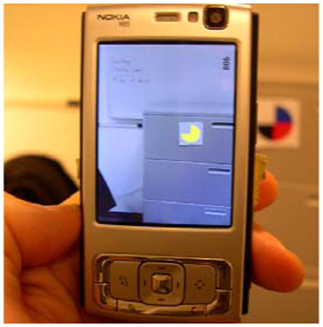
Marker detection and segmentation (shown in yellow) on the cell phone.
The user interface considered for these experiments was very simple. At any time, the application was in one of two possible modes. In the first mode, target detection was communicated to the user via a “beep” sound with three possible pitches, depending on whether the marker was located in the central portion of the image or to the left or to the right of it. The purpose was to allow the user to figure out whether he or she is pointing the camera directly to the marker or to the side. In the second mode, the cell phone reads aloud the distance to the marker upon detection used a prerecorded voice. The set of ranges considered and uttered by the phone was: “Less than 1 meter”; “Between 1 and 3 meters”; “Between 3 and 5 meters”; “More than 5 meters”. The user could toggle between these two modes by simply pressing a large button on the phone. This was in fact the only control available to the user.
3. Experiments
We conducted a number of experiments using color markers in indoor environments with the help of three blind subjects. The broader goals of these tests were:
To validate the effectiveness of color markers for labeling specific locations;
To investigate different search strategies for marker detection, depending on the type of marker placement and the layout of the environment.
The three types of experiments considered, along with a summary of results, are described below.
3.1 Marker perpendicular to the wall
This test was conducted in an office corridor approximately 35 meters long. Color markers (12 cm in diameters) were printed on white paper, and then attached on both sides of square cardboards (18 cm in side). Using Velcro stickers, marker boards could easily be attached to and detached from the mail slots that line the corridor's walls beneath each office door (see Fig. 2(a)). Three markers were attached at equidistant locations on one wall, and two on the opposite wall. However, at most one such marker was placed upside up, with all remaining markers kept upside down. (Note that the current detection algorithm only detects a marker when it is oriented correctly.) The main reason for choosing this strategy rather than just placing at most one marker at a time was that a blind subject may potentially be able to feel the presence of a marker by touching it as he or she passes by. Since all markers are always present (albeit at unknown orientation), casual tactile detection does not represent a problem for the experiments. Another reason was that one of the testers had a minimal amount of vision left, which sometimes enabled him to detect the presence of the marker at approximately one meter of distance. However, the subject had basically no color perception, and was certainly unable to establish the marker's orientation.
Fig 2.
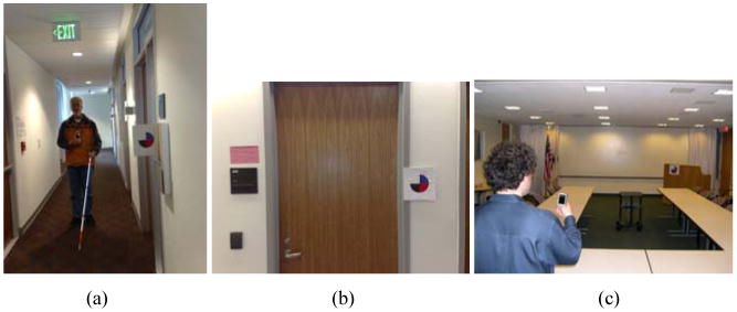
Representative scenes for the three tests. (a): marker perpendicular to the corridor wall. (b): marker flush with the corridor wall. (c): marker in cluttered conference room.
These markers were detectable at a distance of 5-6 meters in this environment. Since they are printed on both faces of the board, markers are visible from any point of the corridor, except when the subject is exactly at the level of the marker (seeing it from the side). A sequence of 15 runs was devised, such that no marker was visible (i.e., correctly oriented) for 6 randomly chosen runs, while one marker was visible at a random location on either side of the wall in the remaining runs. At each run, the subject started from one end of the corridor (chosen at random), and was instructed to walk towards the other end while exploring both walls for the presence of a marker. If a marker was found, the subject was instructed to reach for the handle of the door closest to the marker. The subject was not allowed to change direction (walk back) but could use as much time as he or she wanted for the task. The approximate height of the marker location was fixed and known to the subject. The time elapsed until a door handle was reached or the subject arrived at the other end of the corridor was measured. An initial training phase was conducted for each subject. In particular, subjects were instructed about the correct way to hold the phone and operate the toggle button for distance measurement, and were reminded not to cover the camera with their fingers.
One blind individual (subject A) and one legally blind individual (subject B) who, as described earlier, has very little usable vision left, took part in testing sessions in different days. Subject A normally uses a guide dog for mobility, although he elected not to use the dog during the test, as he was confident that there would be no obstacles on the way. Subject B used his white cane during the tests.
No false detection, leading to reaching the wrong door handle, was recorded during the tests. Indeed, save for a few sporadic false alarms (generating an isolated “beep”), the corridor did not present any patterns that would confuse the system. For the runs where the marker was present, subject A found the marker in all but one run, while subject B found the marker in all runs. Remarkably, both subjects were able to walk at approximately their normal speed while searching for markers. Indeed, both of them developed a search technique based on scanning the environment at ±45° around the vertical axis with a rhythm synchronized with their gait (one full scan every three steps for subject A and every two steps for subject B). Subject A regularly checked for the distance to the marker as soon as the marker was detected and found this operation to be very important. Subject B stopped using the distance measurement function after a while.
3.2 Marker flush with the wall
The second test sequence was run on a different corridor, with the same markers attached directly to the wall (see Fig. 2(b)). A test sequence similar to the previous one was devised, with at most one marker in upright position for each run. However, it was found that it is impractical for the user to search for markers on both walls in this configuration. Since the camera can only detect the marker within a certain angle from the normal, the subject would need to rotate the camera on a 180° span around the vertical axis, which is a somewhat awkward operation. Instead, it was decided to let the subject scan only one wall at the time (the subject was instructed about which wall he may expect to find the marker if present). This marker layout required a different strategy, which was quickly learned by both subjects. Rather than scanning the scene by rotating the cell phone, the optimal strategy turned out to be walking closer to the opposite wall, keeping the phone at 45° with respect to the wall normal. The marker was detectable at a smaller maximum distance than in the previous case, with a higher risk of missing it if the subject walked too fast. Still, no missed detection was recorded out of 10 runs for subject A and 15 runs for subject B. Both subjects were able to walk at their normal speed after a while, with the second subject operating the white cane.
3.3 Marker in cluttered conference room
The purpose of this experiment was to test the search strategies of a blind subject locating a color marker in a cluttered conference room. In each of 10 trials, a 24 cm. diameter color marker was placed in a random location in a conference room (approximately 7 m by 12 m). A third tester (subject C, who is blind) was told that the marker would appear at approximately shoulder height either flush on a wall or other surface (e.g. podium, shown in Fig. 2(c)) or mounted on a portable easel (a stand for displaying a large pad of paper) somewhere in the room. At the start of each trial, the experimenters brought the subject to another random location in the room, chosen so that the color marker was visible to the camera phone system from this location (i.e. the subject would have to pan the cell phone but wouldn't have to move to a different location to detect it); in most, but not all, trials there was also at least one intervening obstacle between the subject and the marker, such as a table, chair or podium. The experimenters timed how long it took the subject to find and touch the color marker in each trial.
After a few practice trials, subject C adopted a fairly consistent search strategy. Holding the cell phone in one hand and the white cane in the other, he began each test trial by panning to locate the color marker, and after detecting it he pressed the button to obtain range information. He then used his white cane to find a clear path to approach the marker by a few meters, and walked rapidly in that direction (often while holding the camera phone down at his side in a position that would not track the target). He would then locate the marker in his new location before approaching still closer. Sometimes he turned on the range function when he was within a few meters of the marker, especially when he felt he was close to the marker but detected an obstacle with the white cane that prevented him from directly approaching it. While he was successful in finding the marker in all ten trials, his style of alternating between tracking/ranging the marker and walking towards it meant that he lost track of the marker from time to time, which delayed him and forced him to backtrack a few steps to locate it again.
4. Conclusions
All of the subjects in our experiments were able to quickly localize and reach for the markers in a variety of fairly realistic environments with a relatively small amount of training. Different search strategies were employed for different environments; these were also quickly learned by our testers. Although more tests are necessary to reach a definite conclusion, our experiments seem to corroborate the hypothesis that the proposed color markers are a viable option for wayfinding.
Overall, all of the subjects were favorably impressed by the performance of the system. Subject A said the he “got to the point of expecting the system to function well rather than expecting a failure to happen at some point”. It should be noticed, though, that in all tests, no other people were present in the corridors or conference room; a crowded environment would likely generate more difficulties for the users. Also, knowing the approximate height of the marker was critical for quick detection. Finally, it is unclear whether the estimation of the distance to the marker is necessary for localization, given the rather different use that the subjects made of this feature.
Acknowledgments
This work was supported by NIH grant 1 R21 EY017003-01A1.
References
- 1.Coughlan J, Manduchi R, Shen H. Cell phone-based wayfinding for the visually impaired. 1st International Workshop on Mobile Vision; Graz, Austria. May 2006. [Google Scholar]
- 2.Coughlan J, Manduchi R. Color targets: Fiducials to help visually impaired people find their way by camera phone. EURASIP Journal on Image and Video Processing – special issue on Image and Video Processing for Disability. 2007 [Google Scholar]
- 3.Crandall W, Bentzen B, Myers L, Brabyn J. New orientation and accessibility option for persons with visual impairment: Transportation applications for remote infrared audible signage. Clinical and Experimental Optometry. 2001 May;84(3):120–131. doi: 10.1111/j.1444-0938.2001.tb04955.x. [DOI] [PubMed] [Google Scholar]
- 4.Fiala M. Proc IEEE CVPR. San Diego: Jun, 2005. ARTag, A fiducial marker system using digital techniques. [Google Scholar]
- 5.Naimark L, Foxlin E. Circular data matrix fiducial system and robust image processing for a wearable vision-inertial self-tracker. Proc ISMAR. 2002 [Google Scholar]
- 6.Rohs M. Real–world interaction with a camera–phone. 2nd International Symposium on Ubiquitous Computing Systems (UCS 2004); Tokyo, Japan. 2004. [Google Scholar]
- 7.Silapachote P, Weinman J, Hanson A, Weiss R, Mattar MA. Automatic sign detection and recognition in natural scenes. Proc IEEE Workshop on Computer Vision Applications for the Visually Impaired (CVAVI '05); San Diego. June 2005. [Google Scholar]
- 8.Roy N Giudice, Legge GE. Digital Sign System for Indoor Wayfinding for the Visually Impaired. Proc IEEE Workshop on Computer Vision Applications for the Visually Impaired (CVAVI '05); San Diego. June 2005. [Google Scholar]