Abstract
Detecting small concentrations of molecules down to the single molecule limit has impact on areas such as early detection of disease, and fundamental studies on the behavior of molecules. Single molecule detection techniques commonly utilize labels such as fluorescent tags or quantum dots, however, labels are not always available, increase cost and complexity, and can perturb the events being studied. Optical resonators have emerged as a promising means to detect single molecules without the use of labels. Currently the smallest particle detected by a non-plasmonically-enhanced bare optical resonator system in solution is a 25 nm polystyrene sphere1. We have developed a technique known as Frequency Locking Optical Whispering Evanescent Resonator (FLOWER) that can surpass this limit and achieve label-free single molecule detection in aqueous solution2. As signal strength scales with particle volume, our work represents a > 100x improvement in the signal to noise ratio (SNR) over the current state of the art. Here the procedures behind FLOWER are presented in an effort to increase its usage in the field.
Keywords: Bioengineering, Issue 106, microtoroid, label-free, single molecule, optical resonator, whispering gallery mode, biosensor, biological detection, frequency locking
Introduction
Single molecule detection experiments are useful for reducing the amount of analyte used in biosensors, for early detection of disease, and for examining the fundamental properties of molecules3. Such experiments are typically performed using labels, however, labels are not always possible to obtain for a particular protein, increase cost, can perturb the events being studied, and can be inconvenient, particularly for real time on-site experiments or point-of-care diagnostics.
The current gold standard for label-free biosensing is surface plasmon resonance4, however the commercial surface plasmon resonance systems typically have a typical lower limit of detection on the order of nM. Recently, optical resonators have emerged as a promising technology for label-free single molecule biodetection5. Optical resonators work based on the long-term (ns) confinement of light6,7. Light is evanescently coupled into these devices typically via an optical fiber. When the wavelength of the light going through the fiber matches the resonance wavelength of the resonator, light efficiently couples to the resonator. This coupled light totally internally reflects within the resonator's cavity generating an evanescent field in the vicinity of the circumference of the resonator. As particles enter the evanescent field and bind to the resonator, the resonance wavelength of the resonator changes in proportion to the volume of the particle8.
In terms of detection capability, microsphere resonators have earlier been used to detect single influenza A virus particles (100 nm)9,10. Recently, plasmonically-enhanced microsphere optical resonators have been used to detect single bovine serum albumin molecules11 and 8-mer oligonucleotides12, however this approach limits the particle capture area to 0.3 µm2 per device. Larger capture area biosensors are ideal for maximizing the chance of particle detection. Current solution-based label-free biosensing technologies with large (> 100 µm2) capture areas have been limited to detecting polystyrene particles ≥ 25 nm.
We have developed a label-free biosensing system based on optical resonator technology known as Frequency Locking Optical Whispering Evanescent Resonator (FLOWER)13 (Figure 1) that is capable of time-resolved detection of single molecules in solution. FLOWER uses the long photon lifetime of microtoroid optical resonators combined with frequency locking feedback control, balanced detection, and computational filtering to detect small particles down to single protein molecules. The use of frequency locking allows the system to always track the shifting resonance of the microtoroid as particles bind, without the need to sweep or scan the laser wavelength over large ranges. The principles of FLOWER may be used to enhance the detection capabilities of other techniques including plasmonic enhancement. In what follows, the procedures for performing FLOWER are described.
Protocol
1. Experimental Setup and Sample Preparation
Fabricate microtoroids using the lithography, etching, and melting procedure as described previously6. Fabricate microtoroids on top of a silicon wafer (chip) that typically have a major diameter of 80-100 µm, and a minor diameter of 2 µm.
Unwind roughly a meter of single-mode optical fiber (125 µm cladding, 4.3 µm mode field diameter) from its fiber spool.
In the middle of the unwound portion of the optical fiber, strip a small segment (2.5 cm) of the polymer coating around the optical fiber using wire strippers. Note: This is the portion of the optical fiber that will be used to evanescently couple light into the microtoroid.
Clean the stripped fiber with isopropanol alcohol and a lint free wipe.
Hold this portion of the fiber in place using a fiber holder made of magnetic clamps.
Thin the stripped fiber to ~500 nm by melting and pulling using a hydrogen torch and two stepper motors moving in opposite directions at 60 µm/min. Position the optical fiber inside the top portion of the flame, which should be ~10 mm tall. Stop pulling the fiber when the transmission through the fiber stops fluctuating, which can be monitored either visually (by watching the light that is scattered laterally from the fiber blink on and off) or by connecting the fiber to a photodiode which is attached to an oscilloscope.
Cleave one end of the optical fiber and insert it into a bare fiber adaptor. Place this end of the fiber into the input of the photoreceiver.
Fiber couple the other end of the fiber spool to the laser by using a fiber optic coupler.
Place the microtoroid chip on top of a sample holder (stainless steel, 37.8 mm x 6.4 mm x 3.2 mm) using either epoxy or double sided tape.
Mount the sample holder on top of a positioning stage that comprises of a 3-axis nano-positioning (nanocube) stage (see equipment list) on top of a 3-axis micrometer. Perform all experiments on a pneumatically isolated optical table to minimize vibrations.
Coarse position the sample chip using the 3-axis micrometer.
Align the microtoroid-containing chip parallel to the optical fiber using the nano-positioner. Note: Align the microtoroid within a distance of one wavelength of the input light (~633 nm). For visualization of this process use two imaging columns (tube with objective lens and camera, see equipment list) positioned on the top and on the side of the chip.
Optimize the polarization of the laser light directed through the optical fiber using an in-line polarization controller (see equipment list) with a knob to adjust the polarization. Note: Optimum polarization is achieved when the measured dip in the transmission of the optical fiber appears the narrowest. Observe this dip on an oscilloscope (see step 2.2 for more details).
Construct a sample chamber by epoxying a glass coverslip over the sample stage using a glass microscope slide as a spacer. Note: A Plexiglas enclosure covering the entire setup may be useful for minimizing air currents. A small opening should be left to allow for the solution to be pumped in using tubing.
Thermally equilibrate particle suspensions or single-molecule aqueous solutions for ≥ 1 hr in a RT water bath (~500 ml). Note: Samples are diluted to the desired concentration in microcentrifuge tubes using the associated buffers specified from the manufacturer, e.g., PBS or HEPES. If no binding events are detected, increase the salt concentration of the buffer.
Vortex particle containing solutions (1 ml) briefly for ~2 sec.
Inject particle containing solutions into the sample chamber at 1 ml/min using a 1 ml syringe pump.
After the sample chamber has filled, turn off the syringe pump.
Wait 30 sec before recording data to minimize the effects of mechanical vibrations resulting from fluid flow that can affect the measurement.
2. Frequency Locking
Re-couple the toroid to the optical fiber by moving the sample holder with the nanopositioner, because the coupling will be disturbed due to the injection of fluid.
Locate the resonance wavelength of the microtoroid by scanning the computer-controlled input laser through a variety of wavelengths. Perform this step by sending a triangular waveform voltage signal to a piezoelectric element within the laser controller that regulates the wavelength of the laser. Perform experiments using visible light (635 nm ± 2.5 nm) as there is low absorption of light in water at this wavelength.
Measure the light transmission through the optical fiber by plugging the output of the optical fiber into an auto-balanced photoreceiver. Plug the output of the photoreceiver into an oscilloscope using a BNC cable. Observe on the oscilloscope that at the resonance wavelength of the microtoroid, transmission through the optical fiber drops.
Attach the output of the photoreceiver to the main input of the frequency locking feedback controller (see equipment list) via a cable.
Run the frequency locking feedback controller in autolock mode using top-of-peak locking with a dither frequency of 2 kHz and an amplitude of wavelength oscillation of 19 fm. Empirically set the proportional-integral-derivative settings in the software window using Ziegler-Nichols tuning rules14. Note: These values need only be set once at the beginning of all experiments.
Auto-lock the wavelength of the laser to the resonance wavelength of the microtoroid. Perform this step after filling the sample chamber. Note: If the wavelength shift is too large, then the feedback controller will lose lock and automatically switch to scanning mode in order to locate the resonance wavelength location. This occurs for wavelength shifts larger than approximately one linewidth (at least 600 fm for all systems investigated here).
Record the output of the feedback controller at 20 kHz using a 24-bit data acquisition card. Export the data as a text file via data acquisition software.
3. Data Processing & Analysis
Fourier transform the data in MATLAB.
Low pass the data using a "brick-wall" filter with a cutoff at 1 kHz to remove the imposed dither frequency of 2 kHz (see Supplemental Code File Screenshot 1).
Computationally notch filter the data using a window size of 16 Hz. Note: This is done to remove known sources of noise, in this case, 60 Hz electronic line noise and its harmonics, as well 100 Hz (coming from the laser driver) and its harmonics (see Supplemental Code File Screenshot 1).
Inverse Fourier transform the data back into the time domain.
Median filter the data using a window size of 1,001 samples (see Supplemental Code File Screenshot 2).
Locate step changes in the resonance wavelength using the step-finding algorithm of Kerssemakers et al.15.
Generate histograms of the amplitude of each binding step.
Calculate particle size using Eq. (1) (see Discussion).
Representative Results
Particle binding events are clearly seen as step-like changes in the resonance wavelength of the microtoroid over time (Figure 2A). The heights of these steps are shown as a histogram in Figure 2B. Figures 2-4 show representative traces from the binding of exosomes (nanovesicles), 5 nm silica beads, and single human interleukin-2 molecules, respectively. The fact that the step-like events scale with particle size shows that the technique has been performed correctly. This may be analyzed by generating a histogram of step heights (Figure 2B) and comparing the maximum step height observed to theoretical predictions, as discussed below.
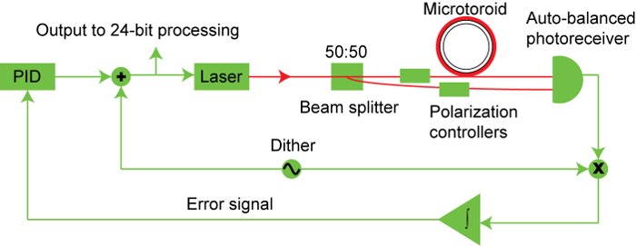 Figure 1. Block diagram of toroid sensing system. Light from a tunable diode laser is split with a portion sent through the optical fiber that couples light into the toroid and the other portion sent directly into one input of an auto-balanced photoreceiver. The output of the optical fiber is sent into the second input of the auto-balanced photoreceiver. The output of the photoreceiver is sent to the feedback controller which modulates the laser light to locate the value of the resonance wavelength of the microtoroid. As particles bind to the toroid, the resonance frequency shifts. The difference between the wavelength of laser and the resonance wavelength of the microtoroid is sent to a proportional-integral-derivative controller that allows the laser to match the wavelength of the toroid as quickly and as smoothly as possible. Please click here to view a larger version of this figure.
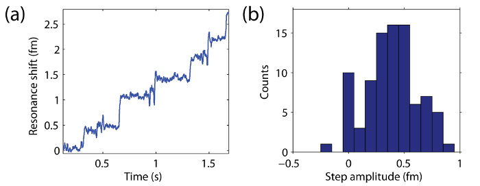 Figure 2. Resonance wavelength change over time as 20 nm beads bind to the surface of the microtoroid. (A) Shift in resonance wavelength of the microtoroid over time as 20 nm beads bind to the surface. (B) Histogram of the heights (amplitudes) of each resonance wavelength step event. Please click here to view a larger version of this figure.
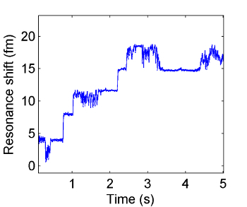 Figure 3. Resonance wavelength change over time as individual exosomes bind to the surface of the microtoroid. Individual binding events are seen as discrete changes (steps) in the resonance wavelength over time. Please click here to view a larger version of this figure.
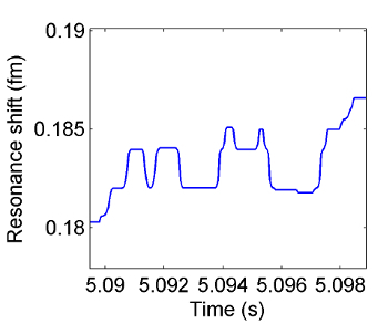 Figure 4. Resonance wavelength change over time as 5 nm silica beads bind to the surface of the microtoroid. Particles adhere to the toroid's surface via passive adsorption. Particle binding events are seen as discrete steps in the resonance wavelength of the toroid over time. Desorption of a particle is seen as a downward step. Please click here to view a larger version of this figure.
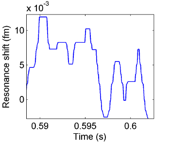 Figure 5. Resonance wavelength change over time as IL-2 molecules bind to the surface of the microtoroid. Macromolecular binding events are seen as discrete steps in the resonance wavelength over time. These steps look similar to those in Figure 4 as the two types of particles are of roughly similar size. Please click here to view a larger version of this figure.
Discussion
As a particle binds, the resonance wavelength (λ) of the toroid increases. If a particle unbinds, the resonance wavelength correspondingly decreases (a step-down event). The particle diameter (d) may be determined through histograms of the amplitude of each wavelength step. The height of each wavelength step varies due to size variations of the bound particle and due to the location on the microtoroid where the particle binds. The maximum change in resonance wavelength (step height) occurs when particles bind at the equator of the microtoroid where the electric field (E0,max) is a maximum. This maximum step height (Δλ) is related to particle diameter through Eq. (1)8, where a is the particle radius, D is a dielectric constant based on the index of refraction of the bound particle and its surrounding media, Vm is the mode volume of light within the microtoroid determined through finite element simulations2, and E0(rs) is the amplitude of the electric field at the particle equator also determined through finite element simulations:

Inverting Eq. (1) indicates that signal strength (Δλ) scales with particle volume (a3). Our dielectric factor is defined as:
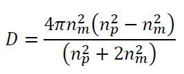
where is the index of refraction of the surrounding media, and is the index refraction of the particle. Theoretical estimates for particle size based on Equation (1) as well as additional histograms and size calculations are presented in 2, 16.
FLOWER may be modified for faster tracking by increasing the frequency at which the frequency locking feedback controller tracks the wavelength of the microtoroid. The data processing procedure can be modified by using a moving average instead of a median filter, and binding events can still be recovered, however the median filter causes step edges to be better preserved. Limitations of this technique include the fact the wavelength shift of the microtoroid upon particle binding depends on where on the resonator the particle lands. Thus, confirmation of the binding of a single particle relies on the generation of a histogram of many discrete binding events. If no distinct binding events are detected, increasing the salt concentration of the solvent helps.
The significance of this technique with regard to existing methods is that no labels are required to interrogate the target molecule. Selective binding however requires functionalizing the sensor with antibodies. Other advantages include the fact that since microtoroid resonators have larger capture areas compared to high sensitivity surface plasmon resonance methods, particle binding events are more likely to occur. In addition, because FLOWER does not require fluorescent tags that may photobleach, FLOWER is capable of long (> 10 sec) measurements with fast (millisecond) time resolution.
Critical steps within the protocol include aligning the optical fiber taper with the microtoroid. Once the toroid is immersed in liquid, too much movement of the fiber through liquid can cause the taper to break, thus ending the experiment. FLOWER in its current formulation is therefore unsuitable for experiments on the time scale of hours. In addition, once the microtoroid has been immersed in liquid and particles bind, the quality factor (Q) irrecoverably drops over a time scale of hours and peak locking may eventually become unstable. In this situation a new device is required. Because we dither our laser frequency in a very small range around the resonance peak, FLOWER does not simultaneously scan across the entire resonance spectrum and therefore does not measure changes in quality factor in real-time as particles bind. Looking at the quality factor before and after the binding of only a few particles, we do not see significant Q factor degradation. We expect that this is because the original pristine toroids have relatively low Q-factor (loaded Q in water of ~ 1x10⁵-5x10⁶).
We note that laser-induced fluctuation noise is subtracted out using the auto-balanced photoreceiver. We minimize fluctuations of the optical fiber against the toroid by placing the fiber in direct contact the microtoroid. Additionally, if PID parameters are not set correctly, fluctuations will appear, i.e., the system will not rapidly and accurately track wavelength shifts. Ziegler-Nichols tuning rules may be used to correctly set the PID settings14. By following the procedures outlined here, it should be possible to detect and size nanoparticles ranging from hundreds of nanometers down to a few nanometers, including single biological molecules.
Disclosures
The authors declare that they have no competing financial interests.
Acknowledgments
This research was supported in part by a National Research Service Award (T32GM07616) from the National Institute of General Medical Sciences.
References
- Lu T, et al. High sensitivity nanoparticle detection using optical microcavities. Proc. Natl. Acad. Sci. U. S. A. 2011;108:5976–5979. doi: 10.1073/pnas.1017962108. [DOI] [PMC free article] [PubMed] [Google Scholar]
- Su J, Goldberg AFG, Stoltz B. Label-free detection of single nanoparticles and biological molecules using microtoroid optical resonators. Light: Science and Applications. 2016. [DOI] [PMC free article] [PubMed]
- Knight A. Single molecule biology. Elsevier/Academic; 2009. [Google Scholar]
- Jonsson U, et al. Real-time biospecific interaction analysis using surface plasmon resonance and a sensor chip technology. BioTechniques. 1991;11:620–627. [PubMed] [Google Scholar]
- Vollmer F, Arnold S. Whispering-gallery-mode biosensing: label-free detection down to single molecules. Nat. Methods. 2008;5:591–596. doi: 10.1038/nmeth.1221. [DOI] [PubMed] [Google Scholar]
- Armani DK, Kippenberg TJ, Spillane SM, Vahala KJ. Ultra-high-Q toroid microcavity on a chip. Nature. 2003;421:925–928. doi: 10.1038/nature01371. [DOI] [PubMed] [Google Scholar]
- Vahala KJ. Optical microcavities. Nature. 2003;424:839–846. doi: 10.1038/nature01939. [DOI] [PubMed] [Google Scholar]
- Arnold S, Khoshsima M, Teraoka I, Holler S, Vollmer F. Shift of whispering-gallery modes in microspheres by protein adsorption. Opt. Lett. 2003;28:272–274. doi: 10.1364/ol.28.000272. [DOI] [PubMed] [Google Scholar]
- Vollmer F, Arnold S, Keng D. Single virus detection from the reactive shift of a whispering-gallery mode. Proc. Natl. Acad. Sci. U. S. A. 2008;105:20701–20704. doi: 10.1073/pnas.0808988106. [DOI] [PMC free article] [PubMed] [Google Scholar]
- He L, Ozdemir SK, Zhu J, Kim W, Yang L. Detecting single viruses and nanoparticles using whispering gallery microlasers. Nat Nano. 2011;6:428–432. doi: 10.1038/nnano.2011.99. [DOI] [PubMed] [Google Scholar]
- Dantham VR, et al. Label-free detection of single protein using a nanoplasmonic-photonic hybrid microcavity. Nano Lett. 2013;13:3347–3351. doi: 10.1021/nl401633y. [DOI] [PubMed] [Google Scholar]
- Baaske MD, Foreman MR, Vollmer F. Single-molecule nucleic acid interactions monitored on a label-free microcavity biosensor platform. Nat Nanotechnol. 2014;9:933–939. doi: 10.1038/nnano.2014.180. [DOI] [PubMed] [Google Scholar]
- Su J. Label-Free Single Exosome Detection Using Frequency-Locked Microtoroid Optical Resonators. ACS Photonics. 2015. pp. 1241–1245.
- Åström KJ, Murray RM. Feedback systems : an introduction for scientists and engineers. Princeton University Press; 2008. [Google Scholar]
- Kerssemakers JW, et al. Assembly dynamics of microtubules at molecular resolution. Nature. 2006;442:709–712. doi: 10.1038/nature04928. [DOI] [PubMed] [Google Scholar]
- Su T-TJ. Label-free detection of single biological molecules using microtoroid optical resonators. California Institute of Technology; 2014. [DOI] [PMC free article] [PubMed] [Google Scholar]


