Abstract
In utero electroporation is a widely used technique for fast and efficient spatiotemporal manipulation of various genes in the rodent central nervous system. Overexpression of desired genes is just as possible as shRNA mediated loss-of-function studies. Therefore it offers a wide range of applications. The feasibility to target particular cells in a distinct area further increases the range of potential applications of this very useful method. For efficiently targeting specific regions knowledge about the subtleties, such as the embryonic stage, the voltage to apply and most importantly the position of the electrodes, is indispensable.
Here, we provide a detailed protocol that allows for specific and efficient in utero electroporation of several regions of the C57BL/6 mouse central nervous system. In particular it is shown how to transfect regions the develop into the retrosplenial cortex, the motor cortex, the somatosensory cortex, the piriform cortex, the cornu ammonis 1-3, the dentate gyrus, the striatum, the lateral septal nucleus, the thalamus and the hypothalamus. For this information about the appropriate embryonic stage, the appropriate voltage for the corresponding embryonic stage is provided. Most importantly an angle-map, which indicates the appropriate position of the positive pole, is depicted. This standardized protocol helps to facilitate efficient in utero electroporation, which might also lead to a reduced number of animals.
Keywords: Neuroscience, Issue 107, In utero electroporation, angle-map, C57BL/6, central nervous system, targeted gene delivery, cortex, hippocampus, thalamus, hypothalamus, lateral septal nucleus, striatum
Introduction
Since the first description in 2001 by three independent groups 1-3 in utero electroporation has become a widely used standard tool for analyzing gene expression in the rodent central nervous system. Compared to the generation of knockout mice, which is, despite continuously improving techniques, still time and money consuming, the in utero electroporation appeals due to its simplicity. So, in utero electroporation enables fast and efficient gain- and loss-of-function studies 4.
To transfect the cerebral regions, the solution containing the negatively charged plasmid is injected into a ventricle. During the electric pulse, the negatively charged DNA migrates towards the positive pole and therefore the transfected region can be selected simply by altering the position of the positive pole. It has frequently been shown that numerous regions of the central nervous system can be targeted 3,5-8. For instance, recent studies show specific transfections of the hippocampus, the piriform cortex or the striatum 9-11. However, the information about the appropriate positions are often only scarcely standardized and are not always easy to transfer to different mouse strains.
Transfection of certain embryonic stages is far from trivial. Many influencing factors must be taken into consideration when choosing the set-up for specific in utero electroporation. First, to optimally transfect the respective embryonic stages, knowledge about the appropriate voltages is needed. High voltages decrease the survival rate, whereas low voltages reduce the transfection efficiency 2,3,12. Also the size of the electrode paddle plays a crucial role, because the use of electrode paddles that are too large results in reduced specificity or can cause death due to affection of the heart rhythm 4,12,13. The applied voltage and the size and the position of the electrode paddle are the most important features to consider, but there are also further factors influencing the outcome of the electroporation, like the applied amount of DNA-solution.
We have developed a detailed protocol which enables fast and efficient transfection of various cerebral regions of the C57BL/6 mouse 12. In this protocol detailed information about the voltages to be used and the size of the electrode paddle for enhanced specificity is provided. Further, information about the ventricle to be filled along with recommendations for the amount of plasmid solution and the position of the electrode is supplied. The indication of the detailed position information in a map and the further visualization of these positions enables straightforward specific and efficient in utero electroporation of the retrosplenial cortex, the motor cortex, the somatosensory cortex, the piriform cortex, the cornu ammonis 1-3, the dentate gyrus, the striatum, the lateral septal nucleus, the thalamus and the hypothalamus.
Protocol
Ethics Statement: The handling of the mice and the experimental procedures were conducted in accordance with European, national and institutional guidelines for animal care.
1. In Utero Electroporation
Note: In utero electroporation was performed as previously published12,14. Therefore, the method is only described briefly in the following (Figure 1).
- Preparations
- Prepare Fast Green colored endotoxin-free advanced transfection-grade plasmid solution (containing 1,5 pCAGGS) as previously described12.
- Pull and grind (35°angle) borosilicate glass capillaries (0.8-0.9 diameter) for injections.
- Sterilize instruments.
- Surgery
- Administer analgesics (carprofen, 4 mg/kg bodyweight, s.c., 24 hr depot) at least 30 min before starting the surgery.
- Keep the length of the anesthesia to a maximum of 35-45 min (Stage III - stage of surgical anesthesia according to Guedel15 - maximal 25-30 min).
- Anesthetize timed pregnant mice with isoflurane (induction in a chamber: 2.8%, surgery via mask: 2.5%). Confirm anesthesia by unresponsiveness to toe-pinch.
- Apply eye ointment to prevent eye-dryness during anesthesia.
- Sterilize the surgical area with 7.5% Providone-Iodine solution and cover the mouse with sterile gauze (moist with 0.9% benzyl alcohol saline solution) with only the surgical area exposed.
- Cut open the abdominal cavity with a scalpel (skin incision: 1.5-2 cm, muscle incision: 1-1.5 cm).
- Preserve the opened abdominal cavity from drying out by moistening with warmed 0.9% benzyl alcohol saline solution or other sterile isotonic solution as directed by veterinary staff or committee.
- Carefully extract uterine horns (using ring forceps, do not touch the uterus with fingers).
- Injection of DNA and electroporation. Note: The exact details for targeting specific regions are indicated in section 2.
- Slowly inject the colored DNA solution into the ventricle as indicated in Figure 1 and section 2 via the prepared borosilicate capillaries.
- Apply the appropriate voltage for the corresponding embryonic stage (e.g., 36-38 V for E14) via specialized forceps-type platinum electrodes (interval cycle length 50 msec, interval pause 950 msec). Pulse the electroporation paddles during the application of the voltage to minimize damage of the uterine wall.
- Post electroporation/ post-operative care
- Carefully replace the uterine horns in the abdominal cavity.
- Suture the muscle and the skin incision separately.
- Let the mouse rest on a thermal support device for recovery.
- Supervise the mouse during recovery (behavior, feed and water consumption), 4 hr, 24 hr and 48 hr after surgery. If necessary, apply additional analgesics (carprofen, 4 mg/kg bodyweight, 24 hr depot) for further 2 days.
2. Transfection of Specific Cerebral Areas
Note: The position of the positive pole is shown as the angle between the vertical centerline through the ventricle filled with the DNA solution (the right or third ventricle) and the position of the positive pole. When filling the left ventricle the positions are mirror-inverted. In Figure 4 the positions of the ear primordial are shown, which provide important reference points.
- Transfection of cortical areas (Figure 2A, Table 1).
- Perform surgery as described in section 1.2. For the in utero electroporation of cortical areas use E14 embryos.
- Inject 1.5-2 µl DNA-solution containing 4 µg DNA in the right lateral ventricle via the prepared borosilicate capillaries.
- Carefully position the embryo by using ring forceps so that there are no visible vessels above the puncture site.
- Slowly inject the DNA-solution approximately 0.75 mm coronal from the lambdoidal suture and 0.5 mm lateral from the sagittal suture (Figure 3). Ensure that the insertion depth is 1.2 mm (E14, measured from the uterine wall). Check for a blue-green colouring with a sharp demarcation.
- Apply voltage via the specialized forceps-type platinum electrodes (interval cycle length 50 msec, interval pause 950 msec).
- Use a 3 or 5 mm electrode paddle.
- Use a voltage ranging from 36-38 V.
- Place the center of the electrodes just anterior of the ear primordia.
- To transfect the retrosplenial cortex use angles from 330-0°, to transfect the motor cortex 0-40°, to transfect the somatosensory cortex 40-95°, to transfect the piriform cortex 95-110° (Figure 2A).
- Perform post electroporation/ post-operative care as described in section 1.4. Sacrifice the mice and analyze the embryos 4 days after electroporation (E18) as described in section 3.
- Transfection of the hippocampus (Figure 2B, Table 1).
- Perform surgery as described in section 1.2. For the in utero electroporation of hippocampal formation use E15 embryos.
- Inject 2 µl DNA-solution containing 4 µg DNA in the right lateral ventricle via the prepared borosilicate capillaries.
- Apply voltage via the specialized forceps-type platinum electrodes (interval cycle length 50 msec, interval pause 950 msec).
- Use a 3 or 5 mm electrode paddle.
- Use a voltage ranging from 38-40.
- Place the center of the negative pole just anterior of the ear primordium and the center of the positive pole at the middle of the ear primordium.
- To transfect the dentate gyrus use angles from 190-210°, to transfect the cornu ammonis (CA)3 210-230°, to transfect the CA2 230-250°, to transfect the CA1 250-275° (Figure 2B).
- Perform post electroporation/ post-operative care as described in section 1.4. Perform analysis after complete hippocampal formation (after birth, p21) as described in section 3.
- Transfection of the lateral septal nucleus and striatum (Figure 2C, Table 1) Note: The angles overlap with those for transfecting the hippocampus. To effectively transfect the lateral septal nucleus and the striatum without unwanted hippocampus transfection earlier embryonic stages (E12) have to be used.
- Perform surgery as described in section 1.2. For the in utero electroporation of the lateral septal nucleus and striatum use E12 embryos.
- Inject 1 µl DNA-solution containing 4 µg DNA in the right lateral ventricle via the prepared borosilicate capillaries.
- Apply voltage via the specialized forceps-type platinum electrodes (interval cycle length 50 msec, interval pause 950 msec).
- Use a 0.5 mm electrode.
- Use 33 V.
- Place the center of the electrodes at the level of the ear primordia.
- To transfect the lateral septal nucleus use angles from 100-170°, to transfect the striatum 170-240° (Figure 2C).
- Perform post electroporation/ post-operative care as described in section 1.4. Sacrifice the mice and analyze the embryos 6 days after electroporation (E18) as described in section 3.
- Transfection of the thalamus and hypothalamus (Figure 2D, Table 1)
- Perform surgery as described in section 1.2. For the in utero electroporation of the thalamus and hypothalamus use E12-E13 embryos.
- Inject 1-1.5 µl DNA-solution containing 4 µg DNA in the lateral ventricle (left or right)via the prepared borosilicate capillaries. Wait for 2-3 min, until the solution is diffused into the third ventricle. Alternatively directly inject into the third ventricle. Note: This enhances specificity but might cause a decreased survival rate (high risk of damage).
- Apply voltage via the specialized forceps-type platinum electrodes (interval cycle length 50 msec, interval pause 950 msec).
- Use a 0.5 or 3 mm electrode.
- Use a voltage ranging from 33-35 V.
- Place the center of the electrodes just posterior the ear primordia.
- To transfect the thalamus use angles from 25-40°, to transfect the hypothalamus 90-180° (Figure 2D).
- Perform post electroporation/ post-operative care as described in section 1.4. Sacrifice the mice and analyze the embryos 6 days after electroporation (E18) as described in section 3.
3. Perfusion Fixation
- Preparations
- Warm 4% paraformaldehyde (PFA) to 37 °C.
- Fill a 50 ml syringe with PBS (4 °C) and a second syringe with warmed PFA. Avoid bubbles.
- Connect the syringes to a three-way stopcock. Connect the third end to a winged infusion set (butterfly).
- Flush the winged infusion set with PBS.
- Perfusion
- Deeply anesthetize the mice (pregnant or postnatal transfected) with subcutaneous application of ketamine hydrochloride (60 mg/ kg) and xylazine (7.5 mg/ kg).
- Confirm the surgical tolerance stage by unresponsiveness to toe-pinch.
- Open the abdominal cavity just beneath the rib cage.
- Carefully cut the diaphragm.
- Carefully open the rib cage via a cut on each site up to the collarbone.
- Insert the tip of the butterfly into the left heart chamber (starting from the apex of the heart).
- Cut the left atrial appendage.
- Slowly perfuse the mouse with PBS (approximately 10 ml).
- Switch the three-way stopcock.
- Perfuse the mouse with 5-10 ml 4% PFA.
- Decapitate the mouse using scissors and dissect the brain beginning at the foramen magnum. Perform the dissection as previously published 16.
- Postfixate the brain for 2 days in 4% PFA. Keep the brains at 4 °C in the dark.
4. Immunohistochemistry
Generate 70 µm sections (e.g., with a vibratome).
- Optional: Enhance fluorescence with antibody staining.
- Block the sections for 1 hr at RT (0.1-0.2% Triton X-100, 5% normal goat serum)
- Incubate O/N with the appropriate antibody (anti-GFP, 1:1,000)
- Wash 3-5 times with 0.1 M phosphate buffer.
- Incubate 3-5 hr with the appropriate fluorescence-conjugated secondary antibody (Alexa Fluor 488 conjugated anti-rabbit-IgG, 1:1,000).
- Optional: Counterstain with 4-6-diaminodino-2-phenylindole (DAPI, 0.2 g/ ml in 0.1 M phosphate buffer) for 1 min.
- Analyze fluorescence with an appropriate fluorescence microscope.
Representative Results
Figure 2, shows examples for the specific in utero electroporation of the regions developing into the retrosplenial cortex, the motor cortex, the somatosensory cortex, the piriform cortex, the cornu ammonis 1-3, the dentate gyrus, the striatum, the lateral septal nucleus, the thalamus and the hypothalamus. The results of the transfections are shown next to the recommended angle (Figure 2). For better visualization of the angles in vivo the position of the electrode (0.5 mm) are also shown on an embryo (Figure 5, embryo in utero, embryo in amniotic sac, dissected embryo). In order to provide an overview Table 1 summarized the relevant facts for specific transfection.
Further, it was demonstrated that the size of the electrode plays a crucial role for the specificity (Figure 6). Larger size of the electrode paddles leads to larger transfected areas, as exemplary shown in Figure 6. Further, electrodes that are too large cover too much of the embryo, thereby enhancing the risk of affecting the embryos heart rhythm (Figure 7). For example a 10 mm electrode paddle covers the whole E12 embryo (Figure 7).
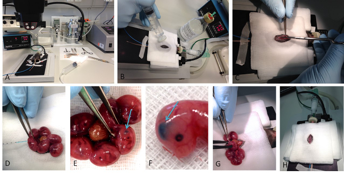 Figure 1. In utero electroporation. Basic steps of the performance of the in utero electroporation are shown. (A) Shows the whole setup of the surgery, with the mouse placed on a hotplate already anesthetized with isoflurane. (B) The disinfection of the surgical area is a crucial step before opening the abdominal cavity (C) of the mouse. (D) The DNA-containing solution is colored with Fast Green, which enables the visualization of successful injection (E, F). Successful injection into a lateral ventricle results into crescent-shaped spot. (G) After the injection the appropriate voltage is applied via forceps type platinum electrodes. (H) After carefully replacing the uterus into the abdominal cavity the surgical wound is sutured. Please click here to view a larger version of this figure.
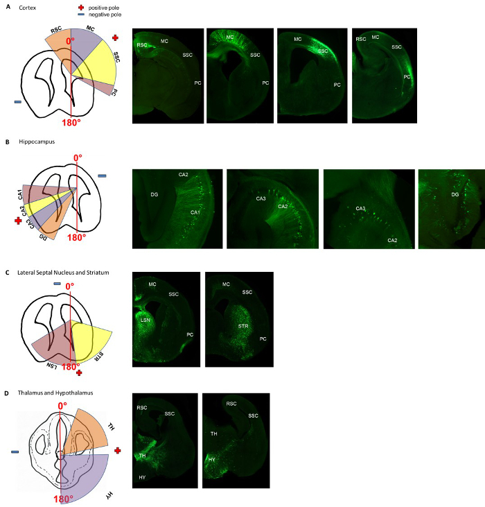 Figure 2. Angle-map for electroporation of specific areas in the murine cortex, hippocampus, lateral septal nucleus, striatum, thalamus and hypothalamus. The appropriate positions for the positive and negative pole, are indicated in the schematic drawing. For (A-C) the positions are indicated for injecting the DNA-solution into the right ventricle. For injections into the left ventricle, the angles are mirror-inverted. The specific transfections were histologically verified. (A) Shows the positions of the positive and negative pole for transfecting cortical areas (the retrosplenial cortex (RSC), the motor cortex (MC), the somatosensory cortex (SSC) and the piriform cortex (PC). (B) Shows the positions of the positive and negative pole for transfecting the hippocampal formations (the cornu ammonis 1-3 (CA1, CA2, CA3) and the dentate gyrus (DG). (C) Shows the positions of the positive and negative pole for transfecting the striatum (STR) and the lateral septal nucleus (LS). (D) Shows the appropriate positions of the electrodes for transfecting the thalamus (TH) and the hypothalamus (HY). Adapted from Baumgart J. & Grebe N., 2015 12.
Please click here to view a larger version of this figure.
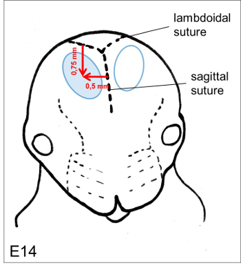 Figure 3. Puncture site. The optimal position for the injection of the DNA solution isapproximately 0.75 mm coronal from the lambdoidal suture and 0.5 mm lateral from the sagittal suture. Please click here to view a larger version of this figure.
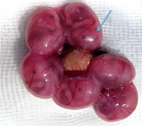 Figure 4. Position of the ear primordium. The position of the ear primordium is clearly defined (arrow). Please click here to view a larger version of this figure.
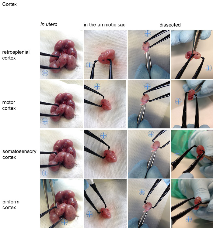
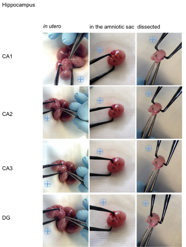
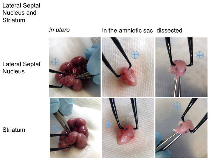
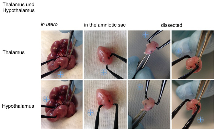 Figure 5. Visualization of the angles on an embryo. For better visualization the appropriate positions for the positive (indicated with a blue plus sign) and the negative pole for specific transfections of the cortical areas (retrosplenial cortex, motor cortex, somatosensory cortex, piriform cortex), the hippocampal areas (cornu ammonis (CA) 1-3, dentate gyrus (DG)), the lateral septal nucleus, the striatum, the thalamus and hypothalamus are shown on an embryo in utero, an embryo in the amniotic sac and on a dissected embryo (all E15,5). Please click here to view a larger version of this figure.
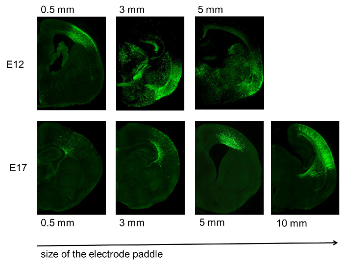 Figure 6. Specificity of transfection depending on the electrode size. Increased size of the electrode paddle reduces the specificity of the transfection. This is especially obvious in younger embryonic stages (E12, top), but also visible in late embryonic stages (E17, bottom). Adapted from Baumgart J. & Grebe N., 2015 12.
Please click here to view a larger version of this figure.
 Figure 7. Size of the electrode paddle compared to the size of an E12 embryo. Electrodes that are too large cover too much of the embryo and therefore increase the risk of affection of the heart rhythm. For example, a 10 mm electrode (on the right) covers the whole E12 embryo and therefore is not recommended, even if specificity is not the primary goal. Adapted from Baumgart J. & Grebe N., 2015 12. Please click here to view a larger version of this figure.
| Targeted region | Angle | Position of the electrode | Age of embryo | DNA amount/ concentration | Voltage | Size of electrode |
| Retrosplenial Cortex | 330°- 0° | Center of the electrodes just anterior of the ear primordia | E14 (E11-E17) | 1.5- 2 µl/ 2.7- 2 µg/µl | 36- 38 | 3- 5 mm |
| Motor Cortex | 0°- 40° | Center of the electrodes just anterior of the ear primordia | E14 (E11-E17) | 1.5- 2 µl/ 2.7- 2 µg/µl | 36- 38 | 3- 5 mm |
| Somatosensory Cortex | 40°- 95° | Center of the electrodes just anterior of the ear primordia | E14 (E11-E17) | 1.5- 2 µl/ 2.7- 2 µg/µl | 36- 38 | 3- 5 mm |
| Piriform Cortex | 95°- 110° | Center of the electrodes just anterior of the ear primordia | E14 (E11-E17) | 1.5- 2 µl/ 2.7- 2 µg/µl | 36-3 8 | 3- 5 mm |
| Cornu Ammonis (CA)1 | 250°- 275° | Center of the positive pole at the middle of the ear primordium | (E14-) E15 | 2 µl/ 2 µg/µl | 38- 40 | 3- 5 mm |
| CA2 | 230°- 250° | Center of the positive pole at the middle of the ear primordium | (E14-) E15 | 2 µl/ 2 µg/µl | 38- 40 | 3- 5 mm |
| CA3 | 210°- 230° | Center of the positive pole at the middle of the ear primordium | (E14-) E15 | 2 µl/ 2 µg/µl | 38- 40 | 3- 5 mm |
| Dentate Gyrus | 190°- 210° | Center of the positive pole at the middle of the ear primordium | (E14-) E15 | 2 µl/ 2 µg/µl | 38- 40 | 3- 5 mm |
| Striatum | 170°- 240° | Center of the electrodes at the level of the ear primordia | E12 | 1 µl/ 4 µg/µl | 33 | 0.5 mm |
| Lateral Septal Nucleus | 100°- 170° | Center of the electrodes at the level of the ear primordia | E12 | 1 µl/ 4 µg/µl | 33 | 0.5 mm |
| Thalamus | 25°- 40° | Center of the electodes just posterior the ear primordia | E12- E13 | 1-1.5 µl/ 4-2.7 µg/µl | 33- 35 | 0.5- 3 mm |
| Hypothalamus | 90°- 180° | Center of the electodes just posterior the ear primordia | E12- E13 | 1-1.5 µl/ 4-2.7 µg/µl | 33- 35 | 0.5- 3 mm |
Table 1: Summary of results. Included in this table is all relevant information for specific transfection of the described cortical areas. It contains details about the targeted region, the angle, the position of the electrode, the embryonic stage, the applied amount and concentration of the DNA solution, the voltage and the size of the electrode.
Discussion
This protocol describes in detail how to transfect the retrosplenial cortex, the motor cortex, the somatosensory cortex, the piriform cortex, the cornu ammonis 1-3, the dentate gyrus, the striatum, the lateral septal nucleus, the thalamus and the hypothalamus of C75BL/6 mice. With all the provided information this is the first protocol, which supplies all necessary information to easily recreate transfections of these cerebral regions in the C57BL/6 mouse. Previous publications are mostly focused only on a few specific regions and therefore the detailed information needed for specific transfections is only scarcely standardized.
The position and the size of the electrode as well as the applied voltage for the corresponding embryonic stage, which are the critical steps for effective and specific transfections, are precisely described. The provided angle-map helps to orientate the electrodes for specific electroporation. The locations of the electrodes are additionally shown on an embryo in the uterus, an embryo in the amniotic sac and also on a pure, dissected embryo. All of this is intended to help in identifying the correct positions of the electrodes.
Usage of the appropriate voltage is a central aspect in the provided protocol. High voltages decrease the survival rate, whereas low voltages reduce the transfection efficiency 2,3,12. Voltage recommendations given in this protocol are specific for C57BL/6 mice and slightly differ from these for CD12,3,12. CD1 mice tolerate higher voltages than C57BL/6 mice and therefore higher voltages might be used for transfecting CD1 mice12. No data exist for other mouse strains, but the standards might need some modifications.
A further central point is the size of the electrode. The usage of a smaller electrode, rather than a bigger one, is always recommended for experiments where specificity is important. Smaller electrodes enhance specificity4,12. If the specificity of the transfection is not the main point, especially for inexperienced experimenters, bigger electrodes enhance the chance of hitting the desired region. Thereby one has to keep in mind that electrodes covering too much of the embryo, might affect the heart rhythm and lead to reduced survival. For example a 10 mm electrode covers the whole E12 embryo and therefore is not recommended for transfecting E12 embryos, even if specificity is not the primary goal.
The stages used in this protocol were chosen exemplary. Considering the fact that progenitors that are transfected on a certain time point give rise to a particular type of neuron the embryonic stages for transfection can be adapted to the specific aim of the study. For instance during cortical development, neurons are born at different time points, forming the six cortical layers in a sequential manner. Hence, depending of the time point of transfection the transfected progenitors give rise to neurons of a specific layer2,17.
For a successful transfection the following points also should be observed. First, the careful preparation and injection of the glass capillaries play a crucial role for the survival of the embryos and therefore for effective transfection. Second, the selection of an appropriate DNA concentration can also be very important and might have to be specifically adapted for different vectors18. Third, application of high voltages affects neighboring embryos, and therefore transfection of neighboring embryos might reduce the survival of these embryos. Further it has also been recommended to avoid the embryos closest to the vaginal duct, because the damage of these embryos might lead to abortion18.
Besides great advantages the technique of in utero electroporation has its drawbacks, which should be taken into consideration while designing experiment. First the regions, which can be efficiently transfected, are manly restricted to areas surrounding the ventricles. This is due to the fact that the plasmid-solution has to be injected into a ventricle. Further, even with all the details provided in this protocol it is not possible to transfect all cells out of a specific region. Even the number of transfected cells is hardly controllable. The analysis of the gene function is not restricted to embryonic stages. Adult mice can also be analyzed because the transfection of postmitotic neurons lasts at least up to 4 months13, but is not passed to the next generation.
Further specifications, such as specifically electroporating thalamic and hypothalamic nuclei or temporally addressing cortical layers can additionally broaden the scope. The combination of genetically engineered mice, or inducible systems in with the in utero electroporation also additionally enhances possible applications.
With all the given facts, this protocol facilitates specific transfections and therefore reduces the number of animal used. Standardization of the protocol additionally enhances the comparability of the obtained results.
Disclosures
The authors have nothing to disclose.
Acknowledgments
Technical supported by Melanie Pfeifer and Nikolai Schmarowski (Institute for Microscopic Anatomy and Neurobiology, University Medical Center Mainz).
References
- Fukuchi-Shimogori T, Grove EA. Neocortex patterning by the secreted signaling molecule FGF8. Science. 2001;294(5544):1071–1074. doi: 10.1126/science.1064252. [DOI] [PubMed] [Google Scholar]
- Saito T, Nakatsuji N. Efficient gene transfer into the embryonic mouse brain using in vivo electroporation. Dev Biol. 2001;240(1):237–246. doi: 10.1006/dbio.2001.0439. [DOI] [PubMed] [Google Scholar]
- Tabata H, Nakajima K. Efficient in utero gene transfer system to the developing mouse brain using electroporation: Visualization of neuronal migration in the developing cortex. Neuroscience. 2001;103(4):865–872. doi: 10.1016/s0306-4522(01)00016-1. [DOI] [PubMed] [Google Scholar]
- LoTurco J, Manent JB, Sidiqi F. New and improved tools for in utero electroporation studies of developing cerebral cortex. Cereb Cortex. 1991;19(Suppl 1)(July):i120–i125. doi: 10.1093/cercor/bhp033. [DOI] [PMC free article] [PubMed] [Google Scholar]
- Nakahira E, Yuasa S. Neuronal generation, migration, and differentiation in the mouse hippocampal primoridium as revealed by enhanced green fluorescent protein gene transfer by means of in utero electroporation. J Comp Neurol. 2005;483(3):329–340. doi: 10.1002/cne.20441. [DOI] [PubMed] [Google Scholar]
- Navarro-Quiroga I, Chittajallu R, Gallo V, Haydar TF. Long-term, selective gene expression in developing and adult hippocampal pyramidal neurons using focal in utero electroporation. J Neurosci. 2007;27(19):5007–5011. doi: 10.1523/JNEUROSCI.0867-07.2007. [DOI] [PMC free article] [PubMed] [Google Scholar]
- Borrell V, Yoshimura Y, Callaway EM. Targeted gene delivery to telencephalic inhibitory neurons by directional in utero electroporation. J Neurosci Methods. 2005;143(2):151–158. doi: 10.1016/j.jneumeth.2004.09.027. [DOI] [PubMed] [Google Scholar]
- Kolk SM, de Mooij-Malsen AJ, Martens GJM. Spatiotemporal Molecular Approach of in utero Electroporation to Functionally Decipher Endophenotypes in Neurodevelopmental Disorders. FNMOL. 2011;4(November):37. doi: 10.3389/fnmol.2011.00037. [DOI] [PMC free article] [PubMed] [Google Scholar]
- Tomita K, Kubo KI, Ishii K, Nakajima K. Disrupted-in-schizophrenia-1 (Disc1) is necessary for migration of the pyramidal neurons during mouse hippocampal development. Hu Mol Gen. 2011;20(14):2834–2845. doi: 10.1093/hmg/ddr194. [DOI] [PubMed] [Google Scholar]
- Niwa M, Kamiya A, et al. Knockdown of DISC1 by In Utero Gene Transfer Disturbs Postnatal Dopaminergic Maturation in the Frontal Cortex and Leads to Adult Behavioral Deficits. Neuron. 2010;65(4):480–489. doi: 10.1016/j.neuron.2010.01.019. [DOI] [PMC free article] [PubMed] [Google Scholar]
- Nakahira E, Kagawa T, Shimizu T, Goulding MD, Ikenaka K. Direct evidence that ventral forebrain cells migrate to the cortex and contribute to the generation of cortical myelinating oligodendrocytes. Dev Biol. 2006;291(1):123–131. doi: 10.1016/j.ydbio.2005.12.010. [DOI] [PubMed] [Google Scholar]
- Baumgart J, Grebe N. C57BL/6-specific conditions for efficient in utero electroporation of the central nervous system. J Neurosci Methods. 2015;240:116–124. doi: 10.1016/j.jneumeth.2014.11.004. [DOI] [PubMed] [Google Scholar]
- Saito T. In vivo electroporation in the embryonic mouse central nervous system. Nat Protc. 2006;1(3):1552–1558. doi: 10.1038/nprot.2006.276. [DOI] [PubMed] [Google Scholar]
- Matsui A, Yoshida AC, Kubota M, Ogawa M, Shimogori T. Mouse in utero electroporation: controlled spatiotemporal gene transfection. JoVE. 2011. [DOI] [PMC free article] [PubMed]
- Guedel AE. Inhalation anesthesia: a fundamental guide. New York: Macmillan; 1937. [Google Scholar]
- Gage GJ, Kipke DR, Shain W. Whole Animal Perfusion Fixation for Rodents. JoVE. 2012. p. e3564. [DOI] [PMC free article] [PubMed]
- Mizutani K, Saito T. Progenitors resume generating neurons after temporary inhibition of neurogenesis by Notch activation in the mammalian cerebral cortex. Development. 2005;132(6):1295–1304. doi: 10.1242/dev.01693. [DOI] [PubMed] [Google Scholar]
- Tabata H, Nakajima K. Labeling embryonic mouse central nervous system cells by in utero electroporation. Dev, Growth & Differ. 2008;50(6):507–511. doi: 10.1111/j.1440-169X.2008.01043.x. [DOI] [PubMed] [Google Scholar]


