

Abstract
Response properties in primary sensory cortices are highly dependent on behavioral state. For example, the nucleus basalis of the forebrain plays a critical role in enhancing response properties of excitatory neurons in primary visual cortex (V1) during active exploration and learning. Given the strong reciprocal connections between hierarchically arranged cortical regions, how are increases in sensory response gain constrained to prevent runaway excitation? To explore this, we used in vivo two-photon guided cell-attached recording in conjunction with spatially restricted optogenetic photo-inhibition of higher-order visual cortex in mice. We found that the principle feedback projection to V1 originating from the lateral medial area (LM) facilitated visual responses in layer 2/3 excitatory neurons by ∼20%. This facilitation was reduced by half during basal forebrain activation due to differential response properties between LM and V1. Our results demonstrate that basal-forebrain-mediated increases in response gain are localized to V1 and are not propagated to LM and establish that subcortical modulation of visual cortex is regionally distinct.
SIGNIFICANCE STATEMENT Reciprocal connectivity among brain regions is a prominent feature of all sensory cortices. In primary visual cortex (V1), top-down signals from association areas aid in context-dependent perception of visual scenes by altering the response properties of individual neurons. Sensory-evoked responses in V1 are also highly dependent on subcortical neuromodulation pathways that regulate brain state. Here, with cell-type-specific resolution, we addressed how corticocortical and subcortical pathways interact to regulate responsiveness of V1. Our results provide insight into the rules and conditions governing activity propagation in reciprocally connected networks.
Keywords: basal forebrain, GABAergic, nucleus basalis, optogenetic, parvalbumin, primary visual cortex
Introduction
The rules and conditions governing activity propagation between reciprocally connected brain regions are poorly understood. Recent studies establish that the visual cortex in mice is hierarchically arranged into functional areas that have distinct preferences for visual features (Wang and Burkhalter, 2007; Andermann et al., 2011; Marshel et al., 2011; Wang et al., 2012; Glickfeld et al., 2013). These higher-order areas provide top-down feedback to primary visual cortex (V1), feedback that is well positioned to convey information regarding context and previously learned statistical features (Gilbert and Li, 2013; Nassi et al., 2014). V1 response properties are also potently altered by subcortical areas such as the nucleus basalis of the forebrain, which enhances the ability to detect sensory stimuli and learn new associations and is essential for increasing visual responses during locomotion and arousal (Bennett et al., 2013; Carcea and Froemke, 2013; Pinto et al., 2013; Fu et al., 2014; Lee et al., 2014). For example, the visual responses of excitatory neurons in layer 2/3 (L2/3) of V1 become more reliable and increase in magnitude 2- to 3-fold during basal forebrain (BF) activation and locomotion. The higher spike rates in V1 are not associated with changes in selectivity (bandwidth) and are therefore indicative of a change in response gain (Goard and Dan, 2009; Polack et al., 2013; Lee et al., 2014). Mechanisms localized within V1 in combination with modulation of antecedent, bottom-up inputs appear to account for arousal-induced increases in response gain in rodents (Goard and Dan, 2009; Polack et al., 2013). The extent to which these changes are propagated to higher visual areas has not been examined systematically. A recent in vivo imaging study raises the possibility that increases in both response gain and reliability are propagated to higher visual areas in a feedforward, supralinear manner (Lecoq et al., 2014).
Despite the importance of corticocortical and subcortical pathways in regulating visual responsiveness, how these two pathways interact during coincident engagement in vivo to optimize vision while maintaining network stability is unknown. To address this, we developed an assay to quantify the contribution of the most prominent source of cortical feedback, the lateral medial area (LM) (Wang and Burkhalter, 2007; Wang et al., 2012), on V1 responsiveness in combination with subcortical BF activation. We found LM facilitates visual responses in L2/3 excitatory neurons by ∼20%. As expected, BF stimulation was associated with widespread desynchronization of the cortical EEG and improved response reliability in V1. We found that the improvement in response reliability, as well as modulation of other response properties, was not propagated to higher-order LM.
In terms of reciprocal connectivity, cortical feedback from LM was not required for basal-forebrain-enhanced visual responsiveness in V1. Furthermore, LM-mediated facilitation was reduced by half during nucleus basalis activation. Our results establish that the impact of top-down feedback on V1 is gated by BF activation. We demonstrate that control of V1 can be internally rebalanced such that L2/3 excitatory neuron response properties are more strongly determined by bottom-up inputs at the expense of LM-mediated feedback during BF activation. This rebalancing may be a critical feature that serves to prevent runaway excitation in reciprocally connected networks.
Materials and Methods
Animal preparation.
All experimental procedures were compliant with the guidelines established by the Institutional Animal Care and Use Committee of Carnegie Mellon University and the National Institutes of Health. Experiments were performed in mice expressing cre-recombinase (cre) and red fluorescence protein (tdTomato) in parvalbumin (PV)-positive neurons derived from the cross between PV-cre knock-in female mice (Jax: 008069, generated by S. Arbor, Friedrich Miescher Institute for Biomedical Research, Basel, Switzerland) and male tdTomato reporter knock-in mouse (Jax:007908, ′Ai14′, generated by H. Zeng, Allen Brain Institute). Recordings were made in cell-attached mode in the left hemisphere visual cortex of 28 urethane-anesthetized mice aged 50 ± 1.2 d at the time of recording.
During surgery, mice (28–41 d old) were anesthetized with isoflurane (3% induction, 1–2% maintenance) and eyes were covered with silicone oil. A stainless steel bar, used to immobilize the head for recordings, was glued to the right side of the skull and secured with dental cement. An ∼2.5-mm-diameter craniotomy was made over the visual cortex in the left hemisphere, identified by coordinates and landmarks as described in Kuhlman and Huang (2008). Expression of channelrhodopsin (ChR) in PV-positive neurons in the visual cortex was achieved by a single tract injection of 250–500 nl of the virus AAV9.EF1a.DiO.hChR2(H134R)-eYFP.WPRE.hGH (UPenn, AV-9-20298P) in the lateral secondary visual cortex every 50 μm, from 750 to 100 μm below the dural surface using a glass micropipette attached to a Picospritzer III (Parker). Post hoc analysis of YFP expression revealed that expression extended throughout and beyond LM in all animals. The area of the craniotomy and the site of injection were confirmed by intrinsic signal imaging as described below. The craniotomy was then covered with a double glass assembly in which the diameter of the inner glass was fitted to the craniotomy and sealed with dental cement. Fourteen to 23 d after injection, the double glass window was removed and a circular 2.5 mm glass coverslip was positioned such that it covered most of the V1 area but allowed access for recording pipettes to penetrate the brain. A silver chloride ground electrode was implanted over the cerebellum and a recording well was made out of dental cement and filled with cortex buffer containing the following (in mm): 125 NaCl, 5 KCl, 10 glucose, 10 HEPES, 2 CaCl2, and 2 MgSO4.
Intrinsic signal optical imaging.
Mapping of the visual cortex was performed through the cranial window in mice 7–14 d after craniotomy and injection. Mice were anesthetized with 0.5% isofluorane and sedated with chlorprothixene (2 mg/kg). The craniotomy window was illuminated with a 630 nm LED (Prizmatix) and imaged with a tandem lens macroscope. For each stimulus, 6 min movies were acquired at 30 frames/s using a 12-bit CCD camera (Dalsa 1M30), a frame grabber (Matrox Meteor II/Dig), and custom software. Frames were binned 4 times temporally and 2 × 2 spatially. Two visual stimuli presented in a LCD monitor (40.5 cm-width, 30 cm-height) positioned 25 cm from the right eye at 70° to the long axis of the animal, covering −22° to 38° in elevation and −27° to 35° in azimuthal space were used. The stimuli presented were a horizontal white bar of 3° in height and a vertical white bar of 4° in width drifting up or down or left or right on a black background at 0.135 Hz.
Visual stimulation.
Visual presentations were generated using custom software developed with PsychToolbox in MATLAB and displayed in a gamma-calibrated LCD monitor positioned as in the intrinsic optical imaging mapping (25 cm from the right eye at 70° to the long axis of the animal). To measure the orientation preference during cell-attached recordings before the silencing experiment (presilencing), full-field drifting square wave gratings were presented at full contrast at six orientations spaced 30° apart at two directions of motion (12 orientations). Stimulus orientations and direction were randomized and each stimulus was presented for 3 s, followed by a gray screen of equal duration repeated in 4–9 trials. The preferred spatial and temporal frequency, typically 0.02 cycles per degree at 1 Hz for PV neurons and 0.04 cycles per degree at 2 Hz for excitatory (Ex) neurons, were used. After determining the preferred orientation, 6 orientations were presented in control and under LED illumination of LM for the duration of the visual stimulus (3 s). In all experiments, trials of control and LED were interleaved across repetitions (typically 15–16 repetitions were measured). The 6 orientations were spaced 30° and spanned from 0° to150° or from 180° to 330°, containing the preferred orientation. Each stimulus was presented for 3 s, followed by a gray screen of equal duration.
In vivo cell-attached recording.
In all cell-attached recordings, mice were anesthetized with urethane (0.5 g/kg) and sedated with chlorprothixene (5 mg/kg). In vivo imaging was performed on a two-photon microscope (Scientifica) using a Chameleon ultra 2 laser (Coherent) running at 930 nm and controlled by ScanImage 3 software (Vidrio Technologies). Surface blood vessels, the coverslip edge, and the pipette were viewed in visible-light conditions at both low (5× objective) and high magnification (40× water-immersion objective; Olympus) using a halogen light source coupled to a fiber optic guide outfitted with a green filter.
Pipettes had a resistance of 5–9 MΩ when filled with cortex buffer containing 20 μm Alexa Fluor-488 hydrazide (Invitrogen). PV neurons were recognized by td-tomato fluorescence and targeted under two-photon imaging; putative excitatory (Ex) neurons were recorded blind. Briefly, 250 mBar of pressure was initially applied to the pipette until the pipette penetrated both the dura and pia matter diagonally at a 35° angle. Once penetrated, pressure was reduced to 60 mBar, the pipette was diagonally moved through L1, and the pressure was reduced to 20–25 mBar in L2/3. The pipette tip relative to the cell surface and resistance were simultaneously monitored during pipette navigation. Contact of the pipette tip with the targeted cell was judged by the concurrence of a sudden increase in resistance and proximity of pipette tip to the soma and pressure was released to 0 mbar. Occasionally, negative pressure was applied. Seals of 0.05–1 GΩ resistance were found to be sufficient to detect and isolate the spikes of single neurons. Electrophysiological signal was acquired with a Multiclamp amplifier in current-clamp mode, a National Instruments digitizer, and WinEDR software (J Dempster, Strathclyde University). Data were analyzed in MATLAB. Signals were sampled at 10 kHz and filtered at 6 kHz. Pipette capacitance was compensated.
The location of the recording site was retinotopically matched to the location of silencing in LM as determined by the intrinsic signal imaging maps for each animal. To silence LM, we stimulated local PV-positive neurons using ChR. Briefly, we modified the two-photon microscope by adding a dichroic mirror (485 LP; Omega Optical) before the viewing head, allowing the illumination of the mouse cortex through the objective with a 470 nm LED light (Mightex). To restrict the size of the LED illumination, a 4 mm pinhole was introduced in the path of the LED light. Due to the heterogeneity in the levels of ChR expression between animals, at the beginning of each experiment, the intensity of the LED light was calibrated by recording visually responsive Ex neurons in LM and assessing the effect of different LED intensities on their response. The minimal LED intensity that produced 100% silencing was used for the experiment. Of the 25 animals used for ChR dependent LM silencing, four were discarded because Ex neurons in LM could not be silenced, presumably due to insufficient ChR expression in LM. Initially, the size of the area of silencing was estimated by recording the ChR evoked response in PV neurons with the LED light centered over the PV neuron soma and then the center of illumination was translated to different positions in the x, y plane relative to the soma of the recorded neuron. To confirm that PV activation maps were consistent with the spatial extent of silencing Ex neurons, the same procedure was repeated except that Ex neurons were recorded (Fig. 1). We determined that the area of silencing had a maximal diameter of 700 μm. In terms of depth, during LED illumination, visually evoked spike rates were reduced by 97 ± 1.9% through LM L5a (450 μm, Fig 1e). At depths beyond the border of L5a/5b in LM, silencing was incomplete; the spike rate was reduced by only 33.6 ± 17.1% at 650 μm (data not shown). In terms of recovery of silencing, we determined empirically that cortical activity was recovered to presilencing evoked rates during control (LEDoff) visual stimulation presentations. We did not detect a difference (paired t test, p = 0.29) between the average evoked rates of L2/3 Ex neurons (n = 16 neurons) at their preferred orientation during presilencing (2.11 ± 0.64 Hz) compared with the control (LEDoff) trials (1.92 ± 0.59 Hz), which were interleaved with LEDon trials.
Figure 1.
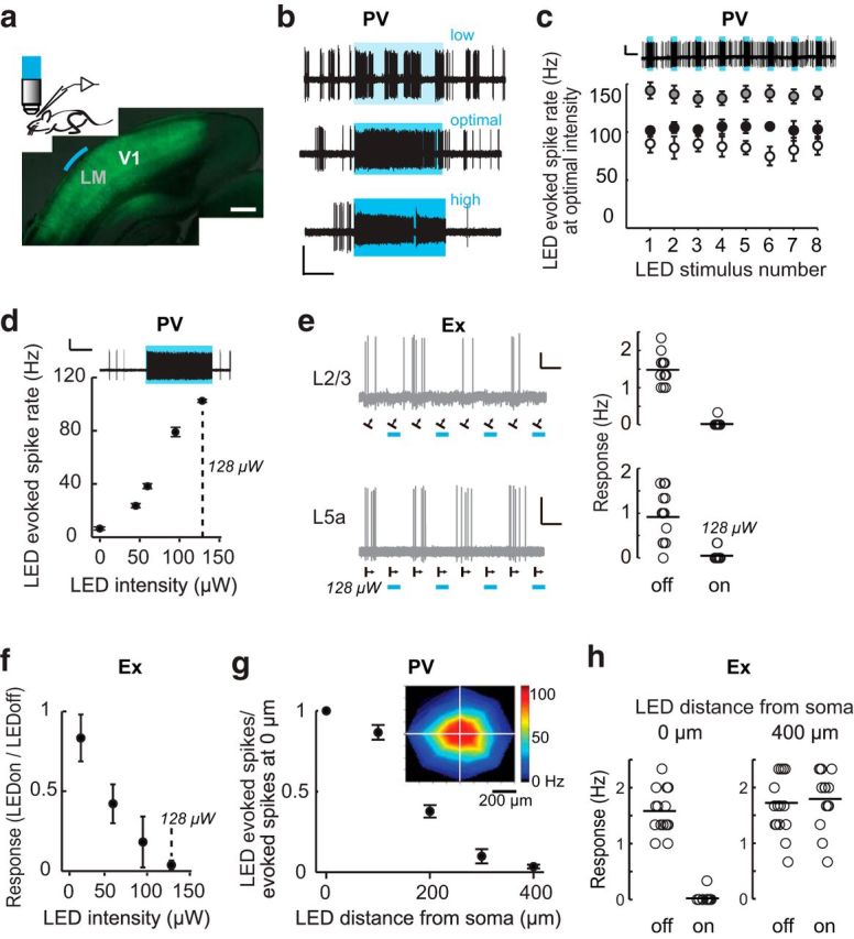
Spatially restricted optogenetic silencing of visual cortex neurons. a, Top, Schematic of recording configuration and example of a fixed coronal section of visual cortex in which PV neurons are transfected with AAV9-DiO-hChR2-eYFP (green). The area of illumination over LM is indicated in blue. Scale bar, 0.5 mm. b, Example traces depicting the selection of optimal LED intensity to stimulate PV neurons. We noted that high LED intensity could induce abnormal firing, defined by a reduction in the action potential amplitude >20% during LED stimulation. Example traces show a cell-attached recording of a L2/3 PV neuron at low (top, 7 μW), optimal (center, 25 μW), and high (bottom, 130 μW) LED intensities, LEDon trials indicated by blue boxes. The LED intensity range used in this manuscript was 22–295 μW (mean value 96 μW). Scale bar, 1 mV, 2 s. c, Reliability of LED activation of PV neurons. Top, Example trace of a cell-attached recording of a L2/3 PV neuron during 8 consecutive LED illuminations at optimal intensity lasting 3 s each, with a 9 s interval between illuminations. Scale bar, 2 mV, 6 s. Bottom, Average response of three individual PV neurons to consecutive LED stimulations. Data are mean ± SEM of three to four trials for each neuron. LED intensities used were, from top to bottom: 95, 128, and 22 μW. d, Average response of an example LM PV neuron located 250 μm below the pia surface in response to LED illumination of increasing intensity. Data are mean ± SEM of eight to 16 trials. Optimal LED intensity was determined to be 128 μW, dashed line and top trace). Scale bar, 2 mV, 3 s. e, Example traces of two LM excitatory neurons recorded in L2/3 (top left, 230 μm below the pial surface) and L5a (bottom left, 450 μm below the pial surface, from the same animal as d during visual stimulation (black arrows show the direction of the visual stimuli). The firing rate of each trial is plotted to the right. Scale bar, 2 mV, 5 s. f, Trial averages for all intensities tested for the L5A neuron shown in e, mean ± SEM of 8 trials. g, Spatial activation of the three PV neurons shown in c, mean ± SEM. The inset shows an individual neuron activation map in x, y coordinates. h, Visually evoked responses from an example excitatory neuron were silenced when the LED was positioned directly over the cell soma (0 μm) and were not affected by LED when the light was positioned 400 μm away from the soma.
BF projections and stimulation.
The projections of the BF in the frontal and visual cortex were determined by expression of the fluorescent protein GFP in the BF neurons in eight mice. Expression of GFP was achieved by injection of the virus AAV2.CAG.GFP (UNC) through a small burr hole in the following stereotaxic coordinates from bregma: AP = −0.7 mm, ML = 1.75 mm, and 4.3 mm below the dural surface in 39- to 48-d-old mice. Then, 150 nl of the virus was delivered using a nanoject system (Drummond Scientific) at a single depth in 3 injections of 50 nl separated by 5 min. Twenty to 21 d after injection, mice were perfused intracardially with 4% paraformaldehyde in PBS. Brains were removed and postfixed for 24 h in the same fixative and sectioned in 60 μm coronal slices using a vibratome. The slices were then stained with Hoechst to determine the laminar distribution of the cortex. Briefly, slices were incubated with a permeabilization solution (0.2% Triton X-100 in PBS) for 30 min at room temperature and then with Hoechst 33342 at a dilution of 1:10,000 (Life Technologies) for 30 min. Slices were then washed three times with PBS, mounted, and imaged with an epifluorescence microscope (Olympus). The border between V1 and LM in visual cortex slices was determined by the pronounced increase in thickness of L4 (van Brussel et al., 2009; Cooke et al., 2015). To quantify the density of BF projection fibers in LM and V1, the coronal slice corresponding to the midpoint of LM in the rostral–caudal axis was selected (4 mm caudal to bregma) and fibers were traced manually using ImageJ software (n = 8 mice). Three different focal planes spaced 20 μm apart were traced and then projected to one image for each slice. LM was defined as 0.05–0.6 mm lateral from the border of V1–LM estimated by Hoechst stain and V1 was defined as 0.05–1 mm medial from the border of V1–LM.
We stimulated the BF using a stimulation electrode in 17 mice, nine of which were used to record the activity of V1 neurons during LM silencing and BF stimulation (seven mice were used for Ex neuron recordings and five mice were used for PV neuron recordings, in three of the nine mice, both types of neurons were recorded), five mice were used in experiments in which Ex LM neurons were recorded during BF stimulation and three mice were used in experiments in which PV LM neurons were recorded during BF stimulation. Before the electrophysiological recordings, a silver chloride electrode was implanted over the surface of the left frontal cortex (AP = 1.9 mm, ML = 0.25 mm) to record EEG and a concentric bipolar stimulation electrode (Plastics1) was stereotaxically implanted in the left BF (AP = −0.7 mm, ML = 1.75 mm, DV = 4.1–4.5 mm). Under urethane anesthesia, the depth of the electrode was adjusted until the power of the prefrontal EEG at 1–10 Hz was successfully reduced by electrical stimulation (50 pulses of 0.1 ms at 100 Hz, of 100–175 uA) as described previously (Alitto and Dan, 2012). Briefly, the stimulation electrode was initially located at a depth of 4.1 mm and 12 repetitions of the electrical stimulation were performed once every 15 s. Custom-made MATLAB routines were used to analyze the power of the EEG recorded in the prefrontal cortex. If no reduction of the power at 1–10 Hz produced by the stimulation was detected, the electrode was moved 0.05–0.1 mm deeper and the stimulation was repeated. Once a successful reduction of EEG power was detected, the intensity of the stimulation was adjusted to produce maximal reduction in EEG power. The stimulation electrode was then fixed in place with dental cement.
Data analysis and statistics.
Events from the electrophysiological recordings in cell-attached configuration were detected in WinEDR using the rate of change of the signal. Custom routines in MATLAB were used to determine the number of events elicited during the visual presentations and to calculate the average firing rate in each condition. For each neuron, the preferred orientation was determined by selecting the orientation to which the neuron responded with the maximal firing rate. The coefficient of variation (CV) was calculated using the evoked rate at the preferred orientation. Tuning curves were obtained by measuring the response at different orientations spaced by 30 degrees. The orientation selectivity index (OSI) and bandwidth were calculated from the best-fitting parameters of a Gaussian function fitted to the tuning curves (Kuhlman and Huang, 2008).
In the experiments in which the BF was electrically stimulated, we quantified the effect of the stimulation by calculating the desynchronization in the EEG recorded in the frontal cortex of urethane-anesthetized mice (Alitto and Dan, 2012) as an EEG power index (1-EEG power Post-Stim1–10Hz/EEG power Pre-Stim1–10Hz). The power ratio was calculated as EEG power at 10–100 Hz divided by EEG power at 1–10 Hz.
Intrinsic optical signal image phase maps of retinotopy were generated as described previously (Kalatsky and Stryker, 2003). Fourier transforms of each pixel in the image sequence, at the frequency of the repeated stimulus were computed using custom scripts in MATLAB. Contour lines indicating iso-elevation and iso-azimuth areas were hand traced from low-pass-filtered phase maps and the different functional areas of visual cortex were labeled as described previously (Marshel et al., 2011). An image of the vasculature at the surface of the cortex in the same location was also captured and the locations of V1 and LM were mapped to the vasculature.
Data are presented either as individual paired values or as mean ± SEM. All datasets were tested for normal distribution in SPSS and normally distributed data were compared using t test, paired t test, ANOVA, or repeated-measures ANOVA as indicated. For cases in which the data were not normally distributed, a nonparametric test was used; paired comparisons were tested using a Wilcoxon signed-rank test, as indicated.
Results
Retinotopic alignment of V1 recordings and spatially restricted photo-inhibition
To quantify the impact of LM feedback on V1 responses, we used an optogenetic approach to silence a restricted area of cortex. Optogenetic silencing of cortex by activating ChR expressed specifically in locally projecting inhibitory neurons (Kuhlman and Huang, 2008) has proven to be a reliable and repeatable method (Li et al., 2013; Lien and Scanziani, 2013; Guo et al., 2014). However, the LM is a relatively small area (0.8 mm2) located adjacent to V1, so to silence this area selectively without modulating the activity of V1 neurons directly, we needed to adapt optogenetic silencing to our particular requirements. In our experiments, ChR was expressed specifically in PV neurons throughout the visual cortex, including the lateral higher visual areas (Fig. 1a), and aperture-restricted LED illumination (470 nm) through a 40× objective lens was used to activate PV inhibitory neurons. Using the aperture-restricted illumination, we determined empirically that cortical silencing was restricted to a 700 μm diameter and, in terms of depth, was effective in silencing Ex neurons through L5a of LM.
Our method of spatially restricted silencing is sensitive to ChR expression level, so to control for differences in expression level across animals, LED intensity was calibrated for each animal by finding the minimum LED intensity sufficient to suppress visually evoked spikes in one or two LM Ex neurons. First, we determined that there was an optimal LED intensity at which light-induced firing rate in PV neurons was highly repeatable (Fig. 1b,c). We next confirmed that the minimum LED intensity required to silence LM Ex neurons effectively fell within this optimal LED intensity range by recording both Ex and PV neurons in the same animal using different LED intensities (Fig. 1d–f). In this manner, we determined that the minimum LED intensity required to suppress visually evoked responses in Ex neurons corresponded to stable activation of PV neurons. To define the spatial limits of silencing, we recorded LED evoked spikes from PV neurons centered directly under the objective and then systematically translated the objective to various distances from the recorded neuron. We noted that LED evoked spike rates in PV neurons was highest at the center of illumination (Fig. 1g). Using this approach, we demonstrated that the radius of cortical silencing is 350 μm (Fig. 1g,h).
Based on the above characterization, we conclude that this method is appropriate for silencing a retinotopically matched region that is >350 μm from the recording site, as well as >350 μm from the areal border. Given that there is noticeable animal-to-animal variation in the cortical representation of visual space (Marshel et al., 2011), before electrophysiological recording, both the location of LM and positioning of V1 recordings were determined using intrinsic signal optical imaging to map retinotopy in each animal used in this study. All V1 recordings were retinotopically aligned to the center of LM silencing within a 100 μm diameter (Fig. 2). Care was taken to ensure that the 700 μm diameter of silencing did not cross the V1–LM border. In addition, retinotopic alignment between LM silencing and V1 recording was confirmed post hoc by projecting the recording and silencing sites onto an averaged x,y-coordinate space (Fig. 2b, bottom right).
Figure 2.

Retinotopic mapping and alignment of recording and silencing sites. a, Schematic of the visual presentation during intrinsic signal imaging; the screen was positioned 25 cm from the contralateral eye at an angle of 70° to the midline. b, Retinotopic maps in response to a vertically (top left) and horizontally (bottom left) moving bar. LM borders (black) were defined by rentinotopic contours. Red and blue circles indicate V1 recording and LM silencing regions, respectively. Bottom right, Silencing and recording sites from 10 of 12 animals were projected onto an averaged coordinate space defined by the lamboid suture and V1–LM phase transition of 10 animals. The center of silencing and recording sites were located 821 ± 50 μm and 657 ± 66 μm from the lamboid suture, respectively, and separated by 896 ± 39 μm.
LM-mediated facilitation is cell-type and orientation specific
Using the silencing method described above in conjunction with cell-attached, extracellular recording of V1 neurons, visual responses to full-field drifting gratings of varying orientations during trials of LM silencing were compared with trials without silencing (Fig. 3). LM silencing resulted in a significant reduction of visually evoked responses in L2/3 Ex neurons specifically at the preferred orientation (two-way mixed factorial ANOVA interaction between orientation and LED state, p = 0.007). We found that LM feedback facilitates the response of L2/3 Ex neurons by ∼20%, specifically at their preferred orientation (Fig. 3c,d). Consistent with this result, LM silencing corresponded with a slight but significant decrease in the OSI (LED off: 0.70 ± 0.06, LED on: 0.66 ± 0.06; paired t test, p = 0.020). Bandwidth of the tuning curves was unchanged (LED off: 18.6 ± 2.6°, LED on: 23.4 ± 3.3°; Wilcoxon signed-rank test, p = 0.179).
Figure 3.

Modulation of visually evoked V1 neuron responses by LM feedback is cell-type specific. a, Schematic of recording configuration. b, Example traces a V1 L2/3 excitatory neuron in response to visual stimulation (black box, arrows indicate presentation angle) in the presence (LEDon) and absence (LEDoff) of LED illumination. Scale bar, 2 mV 0.1 s. Right, Orientation tuning curves of the same neuron as in the left panel in the presence (blue) and absence of LED illumination. c, Impact of LED illumination expressed as percent facilitation of the evoked response at the preferred orientation, averaged across neurons. d–f, Average orientation tuning curves of V1 L2/3 excitatory (n = 16 neurons, 12 mice), L4 excitatory (n = 8 neurons, 6 mice), and L2/3 PV (n = 10 neurons, 5 mice) neurons aligned to their peak response. Each inset shows a representative spike waveform of the cell type recorded. Data are mean ± SEM.
We next examined the impact of silencing LM on L4 Ex neurons, which, unlike L2/3 Ex neurons, typically do not have elaborate dendritic tufts ramifying in L1. In contrast to L2/3 Ex neurons, silencing LM had no impact on L4 Ex neuron orientation tuning curves (Fig. 3e, two-way mixed factorial ANOVA interaction between orientation and LED state, p = 0.907), nor did we detect an effect on either OSI (LED off: 0.61 ± 0.09, LED on: 0.65 ± 0.09; paired t test, p = 0.231) or bandwidth (LED off: 21.3 ± 5.1°, LED on: 19.2 ± 2.1°; paired t test, p = 0.713) in L4 Ex neurons.
Similar to L4 Ex neurons, which also do not have extensive dendritic branching in L1, evoked firing rates of L2/3 PV neurons were not modulated by LM silencing (Fig. 3f; two-way mixed factorial ANOVA interaction between orientation and LED state, p = 0.183). Silencing LM did not modulate the OSI (LED off: 0.14 ± 0.02, LED on: 0.15 ± 0.03; Wilcoxon signed-rank test, p = 0.575) or bandwidth (LED off: 40.4 ± 6.4°, LED on: 39.8 ± 6.3°; paired t test, p = 0.930) of PV neurons. Visually evoked firing rates for all three cell types at the preferred and orthogonal orientations are shown in Figure 4. The majority of V1 Ex neurons showed a reduction in firing rate during LM silencing, whereas most PV neuron responses were insensitive to LM silencing.
Figure 4.
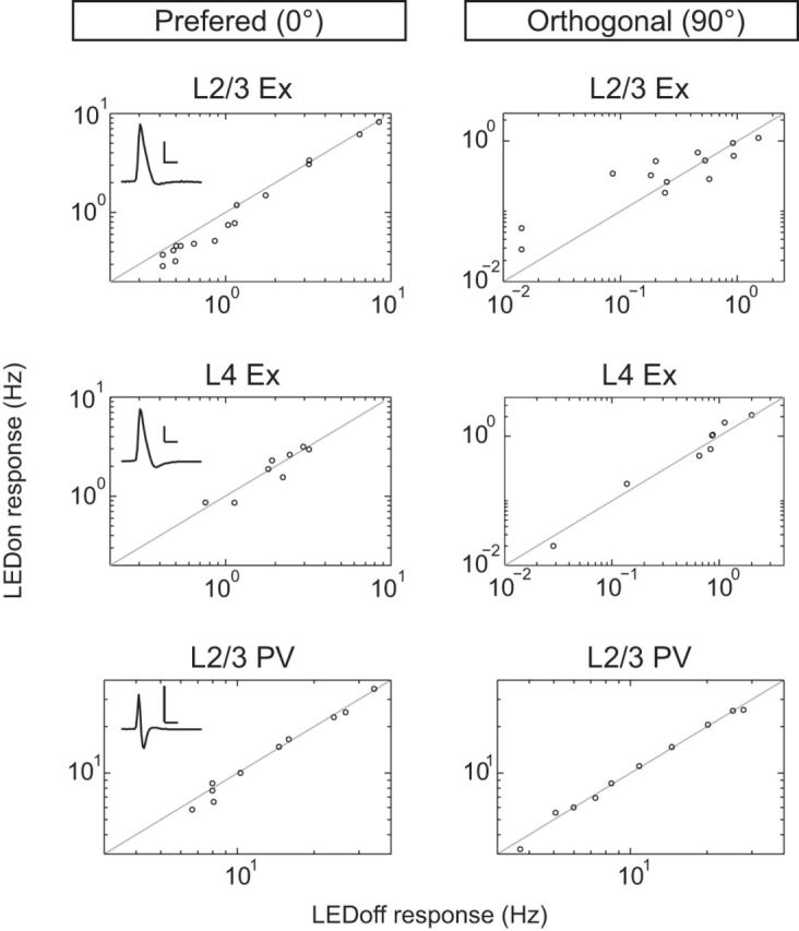
Visually evoked responses of L2/3 excitatory neurons are reduced at the preferred orientation during LM silencing. Spike rates of individual neurons in during LM silencing (LEDon) versus control trials at the preferred (0°, left) and orthogonal orientation (90°, right) are shown in relation to the unity line (black). Scale is adjusted to maximize plotting area. Each inset shows a representative spike waveform of the cell type recorded. Scale bar, 2 mV, 1 s.
Response properties of V1 and LM neurons during BF stimulation
To use our photo-inhibition approach to determine whether corticocortical and subcortical pathways operate synergistically or antagonistically to affect visual responses within V1, we next compared the impact of BF activation on V1 and LM neuron response properties. First we characterized the reliability to which we were able to target the BF by labeling neurons with GFP at the targeted site (coordinates from bregma: ML 1.75 mm, AP −0.7 mm, and 4.3 mm below the dural surface). We found that our subcortical targeting was highly repeatable across animals (Fig. 5). The BF extends ∼2.5 mm in the rostral–caudal axis. The nucleus basalis is contained within this region, spanning −0.035 to +1.35 mm from bregma. The stereotaxic coordinates that we used targeted the center (rostral–caudal), dorsal region of the nucleus basils. Next, we examined the pattern of axonal projection fields. As expected, labeled axons were readily seen throughout both the frontal and visual cortices (Fig. 5b,c). Within the visual cortex, we found that the density of axon fibers was evenly distributed throughout V1 and LM across all cortical layers and specifically within L2/3 (Fig. 5c–e). In terms of the identity of the fibers visualized here, cortically projecting neurons in the targeted area are known to include cholinergic as well as glutamatergic and GABAergic subtypes (Henny and Jones, 2008; Hassani et al., 2009). Subcortically stimulated neurons in this study may also include a newly identified population of cholinergic neurons located at the border of the globus pallidus and BF (Saunders et al., 2015).
Figure 5.

Location and axonal projection pattern of the subcortical region targeted for electrical stimulation. a, Schematic of viral injection location and the rostra-caudal position of coronal slices shown in b–g, sagittal view. b, c, Traced axonal fibers projected from three imaging planes. Yellow line indicates the slice edges and the dashed line indicates the border of L4. Scale bar, 0.5 mm. Inset, Example of a single image plane of the GFP signal used for tracing. Scale bar, 200 μm. d, Quantification of axonal fibers within LM and V1 (n = 8 animals). There was not a significant difference between LM and V1 (all layers, p = 0.613; specifically L2/3, p = 0.831, paired t test). Data are mean ± SEM. e, Hoechst stain reveals the increased thickness of L4 throughout V1, same slice as c. The white arrow indicates the border between V1 and LM. f, g, Characterization of injection site location across animals. In an example slice (f), the blue line indicates the distance from the bifurcation in the white matter and the center of mass of GFP fluorescence (Fcom; yellow plus sign). White scale bar, 0.5 mm (GFP epi-fluorescence image); black scale bar, 1 mm (transmitted light image of the same slice). The medial-lateral distance of Fcom from the white matter bifurcation point was averaged across animals (g, dashed line), as well as the ventral-dorsal distance of the Fcom from the dashed line to create an x, y point (right, black plus sign) that represents the average location of the eight injections. To characterize the average target location in the eight animals examined, the x, y point was overlaid onto a scaled atlas image using the white matter bifurcation as the reference coordinate point (left). B, Nucleus basalis; BLA, basal lateral amygdala; CPu, caudate putamen; GP, globus pallidus; LV, lateral ventricle; IC, internal capsule.
Next, using the above coordinates, BF activity was stimulated with a bipolar electrode positioned in the same hemisphere as the V1 recording site. As expected (Goard and Dan, 2009; Chen et al., 2012), BF stimulation induced a transient desynchronization of the frontal cortical EEG that lasted for a duration of 2.5 s in our conditions (Fig. 6). The amount of cortical desynchronization induced by BF activation was calculated as the EEG power index (Goard and Dan, 2009) and characterized for each animal (Fig. 6g).
Figure 6.

BF stimulation desynchronizes cortical EEG and increases responsiveness of V1 neurons. a, Schematic of electrode placement, sagittal view. b, Representative EEG recording during BF stimulation. Top, Single stimulation trial. Bottom, Spectrogram averaged across 12 trials. Stimulation time is in orange and stimulation artifact on the spectrogram is blank. c, Time course of prefrontal EEG desynchronization induced by BF stimulation. Power ratio, EEG power at 10–100 Hz divided by EEG power at 1–10 Hz. Black line is the mean and the gray line is the SEM (n = 7 mice). d, e, V1 L2/3 excitatory neuron visually evoked responses and CV at the preferred orientation (n = 12 neurons, 7 mice) in the absence (baseline, filled circles) and presence (BF stim, open circles) of BF stimulation. Circles joined by lines indicate paired measures of individual neurons; plus signs indicate mean values. f, Average orientation tuning curves of V1 L2/3 excitatory neurons aligned to their peak response during baseline (filled circles) and BF stimulation (open circles). g, EEG power index, 1-EEG power Post-Stim1-10Hz/EEG power Pre-Stim1-10Hz, of the individual animals shown in c. *p < 0.05; **p < 0.001.
As expected (Goard and Dan, 2009), we found that BF stimulation increased visually evoked spike rates of L2/3 Ex V1 neurons by 2- to 3-fold at the preferred orientation (Fig. 6d) and that the CV across trials was reduced by 15.29 ± 6.7% (Fig. 6e). BF stimulation did not change the OSI (control: 0.63 ± 0.07, BF stim: 0.54 ± 0.06; paired t test, p = 0.162) nor the bandwidth (control: 25.5 ± 3.5°, BF stim: 20.3 ± 4.1°; Wilcoxon signed-rank test, p = 0.182). Therefore, BF stimulation increased response gain and improved response reliability of V1 L2/3 Ex neurons. In striking contrast, neither response gain nor the CV of L2/3 Ex neurons in LM was altered by BF stimulation (Fig. 7). Therefore, LM and V1 are modulated differentially by BF activity.
Figure 7.

LM response properties are unaltered during BF stimulation. a, b, LM L2/3 excitatory neuron visually evoked responses and CV, recorded at the preferred orientation in the absence (baseline, filled circles) and presence of BF stimulation (BF stim, open circles). Circles joined by lines indicate paired measures of individual neurons (n = 10 neurons, 5 mice); plus signs indicate mean values. There was not a significant difference between conditions, Response, p = 0.598 and CV, p = 0.986. c, EEG power index from the experiments shown in a and b. Black line indicates the mean value. d, Average orientation tuning curves of LM L2/3 excitatory neurons aligned to their peak response during baseline (filled circles) and BF stimulation (open circles). Data are mean ± SEM.
Somewhat surprisingly, the increase in V1 responsiveness was not propagated to LM. We considered the possibility that this may be due to the presence of feedforward inhibition. It was previously shown that projections from V1 to LM preferentially target PV inhibitory neurons compared with excitatory neurons (Yang et al., 2013). To address whether feedforward inhibition was responsible for dampening the propagation of a BF-induced increase in V1 gain, we recorded visual responses in PV neurons in LM during BF stimulation compared with baseline conditions in which BF was not stimulated (Fig. 8). If feedforward inhibition were involved, the expected result would be that BF stimulation should increase PV neuron responsiveness in LM. In contrast to the above possibility, we did not find evidence for V1–LM feedforward inhibition contributing to the dampening of propagation. PV visually evoked spike rates in LM were decreased by 29% at the preferred orientation during BF stimulation compared with baseline (BF stimulation: 14.33 ± 2.81 Hz, baseline: 20.12 ± 3.25 Hz). BF stimulation had a similar impact at all orientations, resulting in a significant downward shift of the orientation tuning curve (ANOVA p = 0.033). We next compared these results with PV neurons in V1. Strikingly, the impact of BF stimulation on PV neurons in V1 was distinct from that in LM. In the case of V1 PV neurons, visually evoked spike rates increased by 50% at the preferred orientation (BF stimulation: 29.86 ± 5.26 Hz, baseline: 19.94 ± 3.28 Hz) and significantly shifted the orientation tuning curve upward (ANOVA p = 0.008). Therefore, for both excitatory and PV inhibitory neurons, the impact of BF stimulation on responsiveness was regionally distinct. We found a general increase in responsiveness of both PV and excitatory neurons in V1, whereas in LM, a suppressive effect dominated in which PV neuron responsiveness was reduced and excitatory neuron responsiveness did not increase, as would be expected if propagation from V1 were linear or supralinear.
Figure 8.

LM and V1 neurons are differentially modulated by BF stimulation. Shown are average orientation tuning curves aligned to their peak response during baseline (filled circles) and BF stimulation (open circles) for PV neurons in V1 (n = 8 neurons, 5 mice) and LM (n = 6 neurons, 3 mice). Data are mean ± SEM.
Impact of LM photo-inhibition on the BF-induced increase in V1 response gain
Next, we examined the interaction between the LM corticocortical and BF subcortical pathways in a second group of mice (Group 2). A within-subject comparison revealed that BF stimulation concurrent with LM silencing (BF stimulation + LEDon) increased visually evoked spike rates of L2/3 Ex neurons in V1 at their preferred orientation by 2-fold (Fig. 9a). Furthermore, the CV across trials was also decreased (Fig. 9b). Therefore, LM feedback is not required for BF-induced increases in V1 response gain or improved reliability.
Figure 9.

LM-mediated facilitation is reduced by half during BF stimulation. a, b, V1 L2/3 excitatory neuron visually evoked responses and CV recorded at the preferred orientation in the absence (baseline, filled circles) and presence of BF stimulation in conjunction with LM silencing. Circles joined by lines indicate paired measures of individual neurons (n = 12 neurons, 7 mice); plus signs indicate mean values. c, Impact of LM silencing expressed as percentage facilitation of the evoked response at the preferred orientationaveraged across excitatory neurons in the absence (control, n = 16 neurons, 12 mice; left) and presence (BF stim, n = 12 neurons, 7 mice) of BF stimulation. The predicted reduction (10.3%) for a linear relationship is plotted as a dashed line. Control values are replotted from Figure 3c averaged across PV neurons in the absence (right; control, n = 10 neurons, 5 mice) and presence (BF stim, n = 8 neurons, 5 mice) of BF stimulation. Data are mean ± SEM. d, Silencing and recording sites for the 7 animals in Group 2 were projected onto an averaged coordinate space as in Figure 2. The center of silencing and recording sites were located 967 ± 44 μm and 700 ± 50 μm from the lamboid suture, respectively, and separated by 985 ± 36 μm. Scale bar, 0.5 mm. *p < 0.05; **p < 0.001.
Further within-subject analysis revealed that, during BF stimulation, silencing LM significantly reduced visual evoked spike rates in LM at the preferred orientation (LEDoff: 4.20 ± 0.43 Hz, LEDon: 3.8 ± 0.36 Hz, p = 0.008). Therefore, similar to the results shown in Figures 3 and 4 (Group 1), LM exerted a facilitatory effect. However, the relative amount of facilitation was reduced. A cross-subject comparison between Group 1 and Group 2 revealed that LM-mediated facilitation was reduced by 50% during BF stimulation compared with control conditions (Fig. 9c). Considering that LM output was unchanged by BF stimulation (Fig. 7) and that BF stimulation induced a 2-fold increase in V1 responsiveness, the relative reduction in facilitation indicates that LM feedback is linearly combined with V1 activity and that the 50% reduction can be accounted for by the 2-fold increase in V1 evoked firing rate.
Finally, in a subset of BF-stimulated Group 2 animals, L2/3 PV neuron recordings were obtained. Similar to Group 1, visually evoked responses of L2/3 PV neurons in Group 2 were not facilitated by LM feedback (Fig. 9c). Therefore, we found that cell-type-specific facilitation was maintained in BF-activated conditions.
Discussion
We found that the impact of top-down feedback on V1 is altered by nucleus basalis activation. Our results demonstrate that control of V1 can be internally rebalanced such that L2/3 excitatory neuron response properties are more strongly determined by sensory-driven bottom-up inputs at the expense of LM-mediated feedback. The nucleus basalis of the forebrain is a primary source of cortical acetylcholine (Ach) and is required for enhanced sensory detection during heightened arousal (Hasselmo and Sarter, 2011; Carcea and Froemke, 2013). Our results are generally consistent with classic studies involving recording from in vitro brain slices, which concluded that, in the presence of Ach, cortical flow of activity is altered such that thalamic input is preferentially enhanced through activation of nicotinic Ach receptors and, simultaneously, corticocortical feedback is suppressed by the action of muscarinic Ach receptors (Hasselmo and Sarter, 2011). However, in our in vivo recording conditions, which likely activated all cell types within the subcortical stimulated area including cortically projecting glutamatergic and GABAergic neurons and cholinergic neurons (Bigl et al., 1982; Eckenstein et al., 1988), we found no evidence of corticocortical suppression. During BF activation, LM output was maintained, as well as the absolute contribution of LM-mediated facilitation to V1 responses. Rather, we found a rebalancing of input such that the relative contribution of LM was reduced by 50%.
Technical limitations of photo-inhibition
Characterization of the optogenetic silencing method used in this study confirmed that, in terms of depth, we effectively silenced neurons up to the border of L5a/5b in LM and were able to successfully restrict the area of silencing to a diameter of ≤700 μm. To achieve this restricted area required that we calibrate the light intensity used for each animal and use the lowest light intensity that reliably activated PV neurons. We anticipate that not all methods of expressing ChR in inhibitory neurons will be amenable to achieving the above characteristics, particularly in terms of restricting the area of silencing. For example, in preliminary tests using VGAT transgenic mice in which ChR is genetically expressed in inhibitory neurons (Jackson stock number 014548), we were unable to achieve a restricted area of silencing less than ∼1.2 mm (data not shown). It is important to note that, in our study, neurons deeper than L5a in LM were not completely silenced. It is possible that deep LM neurons could indirectly influence V1 responses through subcortical pathways involving the superior colliculus and thalamus; such indirect influences would not be detected in our assay.
Areal differences in response to BF stimulation
Although BF projections are distributed uniformly across LM and V1, we found key differences in how LM neurons responded to BF stimulation compared with V1 neurons. Despite a 2- to 3-fold increase in V1 evoked spike rates, LM excitatory neurons failed to show an increase in evoked firing rate during BF stimulation. Our results suggest that the mechanisms underlying BF-induced response gain in V1 are not present in LM and that increased V1 responsiveness is not propagated to LM. A possible mechanism that could account for both phenomena would be that feedforward inhibition dominates in the V1–LM pathway (Yang et al., 2013). However, given that we found that the visually evoked firing rate of PV neurons in LM actually decreased during BF stimulation, this possibility is unlikely. Alternatively, regional differences in the expression of signaling molecules such as the muscarinic type 2 acetylcholine receptor (m2AChR) may contribute to response differences and a second, distinct mechanism could be involved in dampening V1–LM propagation. m2AChR expression is lower in LM compared with V1 (Wang et al., 2012; Ji et al., 2015) and activation of presynaptic m2AChRs expressed in PV neuron inhibitory terminals synapsing onto excitatory neurons are known to inhibit the release of GABA (Muñoz and Rudy, 2014). Therefore, the absence of an m2AChR-mediated boosting effect in LM could explain why, although present, stimulation of BF fibers does not result in increased excitability within LM. Additional, unidentified mechanisms likely contribute to the dampening of V1–LM propagation. Consistent with this interpretation, it was previously demonstrated that increases in V1 responsiveness can be accounted for by muscarinic acetylcholine receptors in conditions that induced similar levels of EEG desynchronization used here (Alitto and Dan, 2012).
It has been demonstrated that the modulatory influence of cholinergic signaling is both spatially and temporally precise in awake animals performing specific tasks (Carey and Rieck, 1987; Muñoz and Rudy, 2014). In this study, we established that there are regional differences in the functional response to BF stimulation in vivo within the visual cortex, specifically between LM and V1. The differences are robust and evident in the presence of urethane anesthesia used here. Further studies are needed to identify the precise mechanisms, as well as their time course of action, that contribute to regional differences in responsiveness. It is important to keep in mind that, although using anesthesia has the advantage that experimental variables are tightly controlled, anesthesia does affect ion channel function and may reduce the impact of top-down inputs. Therefore, to fully elucidate the complex interplay between receptor kinetics operating at the level of individual neurons and regional network response properties, studies in awake animals will be informative, particularly when examining temporal dynamics of inhibitory–excitatory balance as it relates to attention and top-down feedback.
Influence of top-down input on V1 response properties
To address how corticocortical and subcortical pathways interact during coincident engagement in vivo, first we characterized the contribution of feedback from LM on the visual responses of three types of neurons: L2/3 excitatory, L2/3 PV inhibitory, and L4 excitatory neurons. L2/3 excitatory neurons are unique in that their dendritic tufts arborize extensively in L1 and possess active membrane properties that contribute to supralinear summation of coincidence input (Larkum, 2013). Given that feedback projections from LM are densest in L1 in combination with the dendritic properties noted above, it is predicted that feedback from higher-order brain areas enhances responsiveness specifically of excitatory neurons (Larkum, 2013; Yang et al., 2013). Here, we tested this prediction directly in vivo and found that, indeed, facilitation was specific to L2/3 excitatory neurons. It is also possible that top-down metabotropic glutamate receptor-mediated suppression of thalamocortical input (De Pasquale and Sherman, 2013) contributed to masking what would otherwise appear as facilitation in V1 L4 Ex neurons. Such an interpretation would be consistent with the finding that, in vitro, stimulation of LM axons provides excitatory input onto V1 L4 Ex neurons (Yang et al., 2013).
It is of interest that we found LM-mediated facilitation to be restricted to the preferred angle of the orientation tuning curve. These results are consistent with a circuit configuration in which similarly tuned excitatory neurons are preferentially connected in a reciprocal manner between V1 and LM, as is observed in primates (Shmuel et al., 2005). Despite the salt-and-pepper organization of response properties such as orientation tuning, it is becoming increasingly apparent that the mouse visual system is highly organized in terms of preferential connectivity between functionally similar neurons (Ko et al., 2011; Glickfeld et al., 2013). This raises important questions regarding how such subnetworks emerge during experience-dependent development (Ko et al., 2013, 2014), as well as what rules may govern the routing of activity during periods of increased response gain. To examine the latter, we designed a paradigm to quantify the interaction between corticocortical and subcortical pathways.
Intersection of corticocortical and subcortical pathways on V1 response properties
Our results demonstrate that LM-mediated facilitation is not required for BF-induced increases in V1 response gain and improvement in response reliability. Moreover, the BF-mediated increase in L2/3 V1 response gain was selective for bottom-up inputs compared with top-down LM feedback. We propose that areal specialization in sensitivity to BF activity, together with asymmetry within the V1–LM reciprocal loop previously described in vitro (De Pasquale and Sherman, 2013; Yang et al., 2013), results in a rebalancing of V1 control such that L2/3 excitatory neuron response properties are more strongly determined by bottom-up inputs during nucleus basalis activation. The transient reduction of LM feedback during conditions that activate the nucleus basalis, such as novel experience (Carcea and Froemke, 2013), may optimize V1 sensitivity to external stimuli by reducing the influence of previously learned visual scene statistics.
Footnotes
This work was supported by the Knights Templar Eye Foundation (D.E.P.), the Howard Hughes Medical Institute Undergraduate Program (M.A.N.), the Fight-For-Sight Foundation (S.J.K.), and the National Institutes of Health (Grant R01EY024678 to S.J.K.).We thank Tony Grace, Tomek Banasikowski, Aryn Gittis, and Rachel Bouchard for help with BF experiments; Spencer Smith, Ikuko Smith, and Ian Nauhaus for assistance in acquiring and analyzing intrinsic signal optical imaging data; and Aryn Gittis and Alison Barth for comments on an earlier version of the manuscript.
References
- Alitto HJ, Dan Y. Cell-type-specific modulation of neocortical activity by basal forebrain input. Front Syst Neurosci. 2012;6:79. doi: 10.3389/fnsys.2012.00079. [DOI] [PMC free article] [PubMed] [Google Scholar]
- Andermann ML, Kerlin AM, Roumis DK, Glickfeld LL, Reid RC. Functional specialization of mouse higher visual cortical areas. Neuron. 2011;72:1025–1039. doi: 10.1016/j.neuron.2011.11.013. [DOI] [PMC free article] [PubMed] [Google Scholar]
- Bennett C, Arroyo S, Hestrin S. Subthreshold mechanisms underlying state-dependent modulation of visual responses. Neuron. 2013;80:350–357. doi: 10.1016/j.neuron.2013.08.007. [DOI] [PMC free article] [PubMed] [Google Scholar]
- Bigl V, Woolf NJ, Butcher LL. Cholinergic projections from the basal forebrain to frontal, parietal, temporal, occipital, and cingulate cortices: a combined fluorescent tracer and acetylcholinesterase analysis. Brain Res Bull. 1982;8:727–749. doi: 10.1016/0361-9230(82)90101-0. [DOI] [PubMed] [Google Scholar]
- Carcea I, Froemke RC. Cortical plasticity, excitatory-inhibitory balance, and sensory perception. Prog Brain Res. 2013;207:65–90. doi: 10.1016/B978-0-444-63327-9.00003-5. [DOI] [PMC free article] [PubMed] [Google Scholar]
- Carey RG, Rieck RW. Topographic projections to the visual cortex from the basal forebrain in the rat. Brain Res. 1987;424:205–215. doi: 10.1016/0006-8993(87)91463-6. [DOI] [PubMed] [Google Scholar]
- Chen N, Sugihara H, Sharma J, Perea G, Petravicz J, Le C, Sur M. Nucleus basalis-enabled stimulus-specific plasticity in the visual cortex is mediated by astrocytes. Proc Natl Acad Sci U S A. 2012;109:E2832–E2841. doi: 10.1073/pnas.1206557109. [DOI] [PMC free article] [PubMed] [Google Scholar]
- Cooke SF, Komorowski RW, Kaplan ES, Gavornik JP, Bear MF. Visual recognition memory, manifested as long-term habituation, requires synaptic plasticity in V1. Nat Neurosci. 2015;18:262–271. doi: 10.1038/nn.3920. [DOI] [PMC free article] [PubMed] [Google Scholar]
- De Pasquale R, Sherman SM. A modulatory effect of the feedback from higher visual areas to V1 in the mouse. J Neurophysiol. 2013;109:2618–2631. doi: 10.1152/jn.01083.2012. [DOI] [PMC free article] [PubMed] [Google Scholar]
- Eckenstein FP, Baughman RW, Quinn J. An anatomical study of cholinergic innervation in rat cerebral cortex. Neuroscience. 1988;25:457–474. doi: 10.1016/0306-4522(88)90251-5. [DOI] [PubMed] [Google Scholar]
- Fu Y, Tucciarone JM, Espinosa JS, Sheng N, Darcy DP, Nicoll RA, Huang ZJ, Stryker MP. A cortical circuit for gain control by behavioral state. Cell. 2014;156:1139–1152. doi: 10.1016/j.cell.2014.01.050. [DOI] [PMC free article] [PubMed] [Google Scholar]
- Gilbert CD, Li W. Top-down influences on visual processing. Nat Rev Neurosci. 2013;14:350–363. doi: 10.1038/nrn3476. [DOI] [PMC free article] [PubMed] [Google Scholar]
- Glickfeld LL, Andermann ML, Bonin V, Reid RC. Cortico-cortical projections in mouse visual cortex are functionally target specific. Nat Neurosci. 2013;16:219–226. doi: 10.1038/nn.3300. [DOI] [PMC free article] [PubMed] [Google Scholar]
- Goard M, Dan Y. Basal forebrain activation enhances cortical coding of natural scenes. Nat Neurosci. 2009;12:1444–1449. doi: 10.1038/nn.2402. [DOI] [PMC free article] [PubMed] [Google Scholar]
- Guo ZV, Li N, Huber D, Ophir E, Gutnisky D, Ting JT, Feng G, Svoboda K. Flow of cortical activity underlying a tactile decision in mice. Neuron. 2014;81:179–194. doi: 10.1016/j.neuron.2013.10.020. [DOI] [PMC free article] [PubMed] [Google Scholar]
- Hassani OK, Lee MG, Henny P, Jones BE. Discharge profiles of identified GABAergic in comparison to cholinergic and putative glutamatergic basal forebrain neurons across the sleep-wake cycle. J Neurosci. 2009;29:11828–11840. doi: 10.1523/JNEUROSCI.1259-09.2009. [DOI] [PMC free article] [PubMed] [Google Scholar]
- Hasselmo ME, Sarter M. Modes and models of forebrain cholinergic neuromodulation of cognition. Neuropsychopharmacology. 2011;36:52–73. doi: 10.1038/npp.2010.104. [DOI] [PMC free article] [PubMed] [Google Scholar]
- Henny P, Jones BE. Projections from basal forebrain to prefrontal cortex comprise cholinergic, GABAergic and glutamatergic inputs to pyramidal cells or interneurons. Eur J Neurosci. 2008;27:654–670. doi: 10.1111/j.1460-9568.2008.06029.x. [DOI] [PMC free article] [PubMed] [Google Scholar]
- Ji W, Gămănuţ R, Bista P, D'Souza RD, Wang Q, Burkhalter A. Modularity in the organization of mouse primary visual cortex. Neuron. 2015;87:632–643. doi: 10.1016/j.neuron.2015.07.004. [DOI] [PMC free article] [PubMed] [Google Scholar]
- Kalatsky VA, Stryker MP. New paradigm for optical imaging: temporally encoded maps of intrinsic signal. Neuron. 2003;38:529–545. doi: 10.1016/S0896-6273(03)00286-1. [DOI] [PubMed] [Google Scholar]
- Ko H, Hofer SB, Pichler B, Buchanan KA, Sjöström PJ, Mrsic-Flogel TD. Functional specificity of local synaptic connections in neocortical networks. Nature. 2011;473:87–91. doi: 10.1038/nature09880. [DOI] [PMC free article] [PubMed] [Google Scholar]
- Ko H, Cossell L, Baragli C, Antolik J, Clopath C, Hofer SB, Mrsic-Flogel TD. The emergence of functional microcircuits in visual cortex. Nature. 2013;496:96–100. doi: 10.1038/nature12015. [DOI] [PMC free article] [PubMed] [Google Scholar]
- Ko H, Mrsic-Flogel TD, Hofer SB. Emergence of feature-specific connectivity in cortical microcircuits in the absence of visual experience. J Neurosci. 2014;34:9812–9816. doi: 10.1523/JNEUROSCI.0875-14.2014. [DOI] [PMC free article] [PubMed] [Google Scholar]
- Kuhlman SJ, Huang ZJ. High-resolution labeling and functional manipulation of specific neuron types in mouse brain by Cre-activated viral gene expression. PLoS One. 2008;3:e2005. doi: 10.1371/journal.pone.0002005. [DOI] [PMC free article] [PubMed] [Google Scholar]
- Larkum M. A cellular mechanism for cortical associations: an organizing principle for the cerebral cortex. Trends Neurosci. 2013;36:141–151. doi: 10.1016/j.tins.2012.11.006. [DOI] [PubMed] [Google Scholar]
- Lecoq J, Savall J, Vučinić D, Grewe BF, Kim H, Li JZ, Kitch LJ, Schnitzer MJ. Visualizing mammalian brain area interactions by dual-axis two-photon calcium imaging. Nat Neurosci. 2014;17:1825–1829. doi: 10.1038/nn.3867. [DOI] [PMC free article] [PubMed] [Google Scholar]
- Lee AM, Hoy JL, Bonci A, Wilbrecht L, Stryker MP, Niell CM. Identification of a brainstem circuit regulating visual cortical state in parallel with locomotion. Neuron. 2014;83:455–466. doi: 10.1016/j.neuron.2014.06.031. [DOI] [PMC free article] [PubMed] [Google Scholar]
- Li YT, Ibrahim LA, Liu BH, Zhang LI, Tao HW. Linear transformation of thalamocortical input by intracortical excitation. Nat Neurosci. 2013;16:1324–1330. doi: 10.1038/nn.3494. [DOI] [PMC free article] [PubMed] [Google Scholar]
- Lien AD, Scanziani M. Tuned thalamic excitation is amplified by visual cortical circuits. Nat Neurosci. 2013;16:1315–1323. doi: 10.1038/nn.3488. [DOI] [PMC free article] [PubMed] [Google Scholar]
- Marshel JH, Garrett ME, Nauhaus I, Callaway EM. Functional specialization of seven mouse visual cortical areas. Neuron. 2011;72:1040–1054. doi: 10.1016/j.neuron.2011.12.004. [DOI] [PMC free article] [PubMed] [Google Scholar]
- Muñoz W, Rudy B. Spatiotemporal specificity in cholinergic control of neocortical function. Curr Opin Neurobiol. 2014;26:149–160. doi: 10.1016/j.conb.2014.02.015. [DOI] [PMC free article] [PubMed] [Google Scholar]
- Nassi JJ, Gómez-Laberge C, Kreiman G, Born RT. Corticocortical feedback increases the spatial extent of normalization. Front Syst Neurosci. 2014;8:105. doi: 10.3389/fnsys.2014.00105. [DOI] [PMC free article] [PubMed] [Google Scholar]
- Pinto L, Goard MJ, Estandian D, Xu M, Kwan AC, Lee SH, Harrison TC, Feng G, Dan Y. Fast modulation of visual perception by basal forebrain cholinergic neurons. Nat Neurosci. 2013;16:1857–1863. doi: 10.1038/nn.3552. [DOI] [PMC free article] [PubMed] [Google Scholar]
- Polack PO, Friedman J, Golshani P. Cellular mechanisms of brain state-dependent gain modulation in visual cortex. Nat Neurosci. 2013;16:1331–1339. doi: 10.1038/nn.3464. [DOI] [PMC free article] [PubMed] [Google Scholar]
- Saunders A, Oldenburg IA, Berezovskii VK, Johnson CA, Kingery ND, Elliott HL, Xie T, Gerfen CR, Sabatini BL. A direct GABAergic output from the basal ganglia to frontal cortex. Nature. 2015;521:85–89. doi: 10.1038/nature14179. [DOI] [PMC free article] [PubMed] [Google Scholar]
- Shmuel A, Korman M, Sterkin A, Harel M, Ullman S, Malach R, Grinvald A. Retinotopic axis specificity and selective clustering of feedback projections from V2 to V1 in the owl monkey. J Neurosci. 2005;25:2117–2131. doi: 10.1523/JNEUROSCI.4137-04.2005. [DOI] [PMC free article] [PubMed] [Google Scholar]
- van Brussel L, Gerits A, Arckens L. Identification and localization of functional subdivisions in the visual cortex of the adult mouse. J Comp Neurol. 2009;514:107–116. doi: 10.1002/cne.21994. [DOI] [PubMed] [Google Scholar]
- Wang Q, Burkhalter A. Area map of mouse visual cortex. J Comp Neurol. 2007;502:339–357. doi: 10.1002/cne.21286. [DOI] [PubMed] [Google Scholar]
- Wang Q, Sporns O, Burkhalter A. Network analysis of corticocortical connections reveals ventral and dorsal processing streams in mouse visual cortex. J Neurosci. 2012;32:4386–4399. doi: 10.1523/JNEUROSCI.6063-11.2012. [DOI] [PMC free article] [PubMed] [Google Scholar]
- Yang W, Carrasquillo Y, Hooks BM, Nerbonne JM, Burkhalter A. Distinct balance of excitation and inhibition in an interareal feedforward and feedback circuit of mouse visual cortex. J Neurosci. 2013;33:17373–17384. doi: 10.1523/JNEUROSCI.2515-13.2013. [DOI] [PMC free article] [PubMed] [Google Scholar]