Synopsis
With the introduction of clinical PET/MR systems, novel attenuation correction methods are needed, as there are no direct or indirect MR methods to measure the attenuation of the objects in the FOV. A unique challenge for PET/MR attenuation correction is that coils for MR data acquisition are located in the FOV of the PET detector and could induce significant quantitative errors. In this review, we summarize and evaluate current methods and techniques to correct for the attenuation of a variety of coils.
Keywords: PET/MRI, Attenuation correction, MRI surface coils, PET/MR reconstruction, scatter correction, image analysis
1) Introduction
Positron Emission Tomography (PET) is a functional imaging technique that displays the bio-distribution of externally administered radioactive tracers to the body. The measurement of tracer concentrations down to picomolar concentrations is a unique advantage of PET1. However, several physical effects such as attenuation, scatter, random coincidences and detector efficiency normalization must be accounted for in order to achieve an accurate quantification1,2.
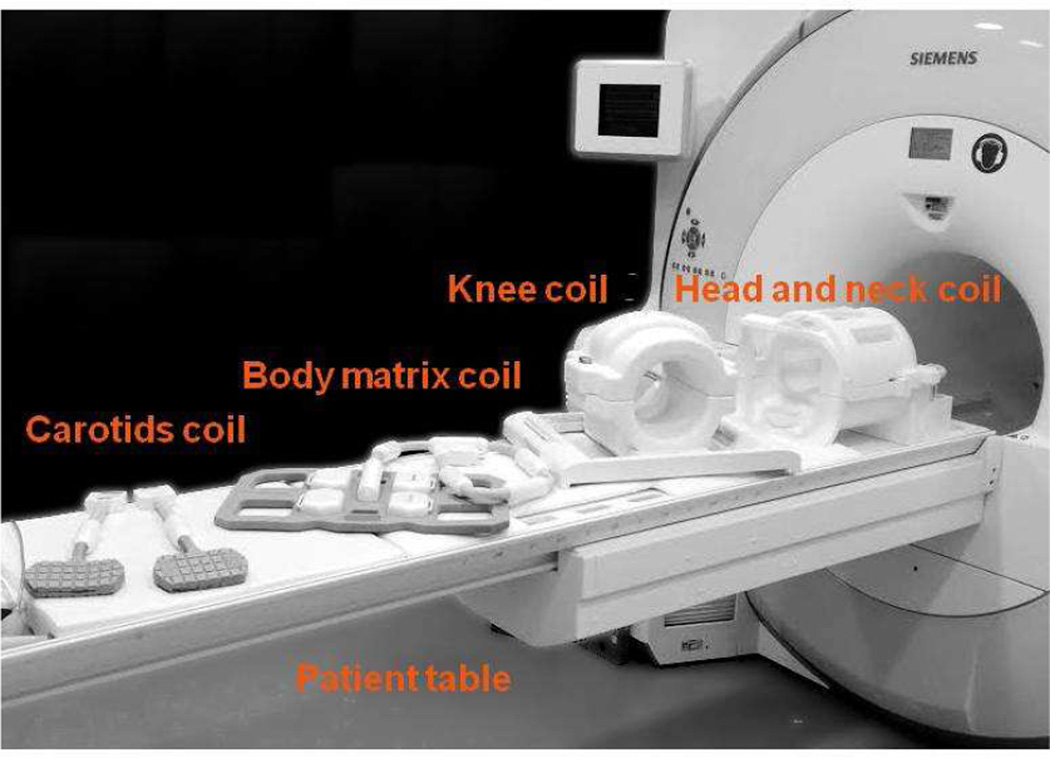
Attenuation of PET photons by all objects in the field of view (FOV) is one of the major challenges of PET imaging, leading to the underestimation of tracer uptake and to image artifacts3. In all PET systems (i.e. stand-alone, PET/CT, or PET/MR), attenuation correction (AC) must be applied for the patient body, patient positioning aids (i.e. cushions and pillows), as well as the patient table. PET/MR systems are unique because imaging coils such as head and neck, knee, cardiac, or carotid coils are used to detect the MR signal as shown in Figure 1.
Figure 1.
Image of a biograph mMR along with several receiver coils.
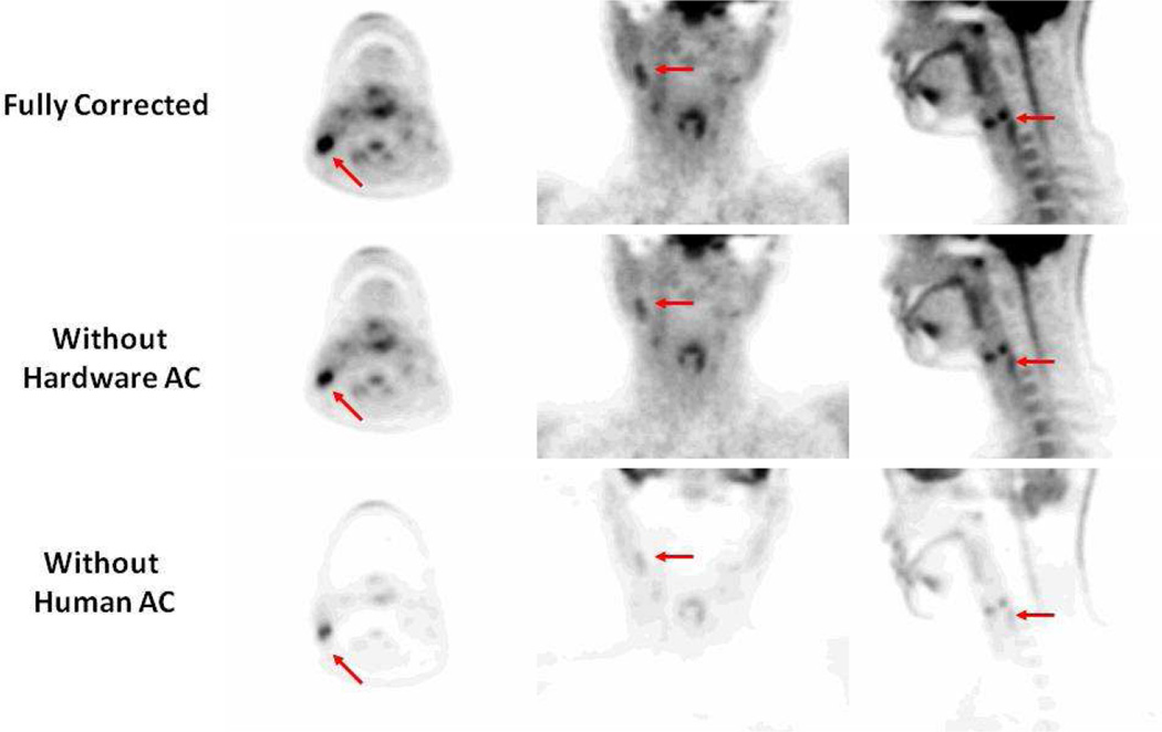
To visualize the effect of attenuation on quantification, Figure 2A shows an example of a fully corrected PET image for attenuation of both the patient as well as MR hardware, including the patient table and the head and neck coil. If the attenuation for MR imaging hardware is not account for as in Figure 2B, the measured uptake is considerably reduced. If the attenuation of the patient is not accounted for (Figure 2C) an even larger error is observed. As a result, AC for all objects must be applied in order to quantify the tracer uptake accurately.
Figure 2.
Sample PET images. The top panel shows a fully corrected PET image. The middle panel is a PET image reconstructed without account for the MR hardware including the patient table and the head and neck coil. Bottom panel: is the PET image reconstructed without human attenuation correction.
Hybrid PET scanners mainly exist as systems combined with either a CT or MR scanner. In combined PET/CT systems, AC is performed using the CT data that is sequentially acquired during the same exam. In case of PET/MR, the MR signal is unrelated to attenuation or electron density and thus cannot be directly used for AC. As a result, different attenuation correction strategies were needed depending on whether one is correcting for the attenuation of the patient or the MR hardware (i.e. coils and patient table)4–8. Several review articles have focused on AC methods for patients9–11. In this review article, we will summarize currently published work on attenuation correction for MR coils and hardware. We will also discuss limitations and opportunities to further develop methods and applications.
2) PET/MR Coils
MR surface coils are electronic equipment that vary in size and shape depending on their application. They are made of a mix of materials including plastic and rubber, but most relevant are conducting materials for wiring and electronic circuitry. The attenuation of gamma rays is directly related to the electron density distribution of the material. Hence, it might be feasible to optimize the design of the MR coils with respect to lower attenuation properties and, when possible, with materials that do not affect the PET signal significantly. In a simulation study that aimed to recommend optimized configurations, it was found that plastics such as polytetrafluoroethylene are less suitable for coils than polyethylene for example12. It was also concluded that dense materials such as capacitors have a significant impact on attenuation and should be moved away from the patient. The findings of this simulation study were applied recently for a design of a PET/MR optimized head and neck coil13. The coil used thin plastic housing, thin copper wires, and attempted to move the electronics as far away from the PET FOV as possible. The attenuation properties of the coil were compared to the standard head and neck coil. The optimized design of the coil resulted in significantly lower attenuation with a remaining 20% error in quantification13. Hence, even for optimized coil designs with least attenuation effects, the AC must not be omitted currently.
Additional studies were performed with optimized PET/MR coils such as the body matrix coil14. The use of the coil resulted in errors that reached 20% in areas near highly attenuating parts of the coil which come in close vicinity to the patient. The authors concluded that AC is required for the optimized body matrix coil15.
Taken together, while it is relevant to optimize the design of PET/MR coils with respect to attenuation, the design of completely PET-transparent coils is not yet possible and AC must be applied if they are to be used for quantitative PET exams on the hybrid PET/MR scanner13,16.
3) Attenuation correction for MRI coils
While several MR based methods have been proposed to correct for body tissue attenuation in combined PET/MR imaging, AC for MR coils, particularly flexible MR coils, remains an active area for research and development14,15,17–23. For rigid coils, such as the head and the spine matrix coils, the attenuation map can be generated, memorized, and used in the PET reconstruction whenever the specific portion of coils is within the FOV of the scan23. This is possible because such coils retain their position in the PET FOV for all scans allowing for the use a fixed template attenuation map for AC. Currently available commercial PET/MR scanners utilize either transmission- or CT-based attenuation maps for rigid MR hardware, which will be discussed in the next section23,24. Flexible coils, on the other hand, change their shape and position from one imaging session to the next in adaptation the size of the patient. Additionally, the coils may move during the acquisition primarily due to physiologic or involuntary movements of the patient25. This makes the use of a fixed template attenuation map currently not feasible or impractical. Examples of flexible MR coils include cardiac coils, carotid coils, and the body matrix coil. By design, flexible MR coils are purposely invisible in conventional PET and MR imaging, which makes accurate localization of such coils in the PET FOV a challenging task. As a result of these challenges, AC for flexible coils is currently not implemented in commercially available PET/MR scanners despite the fact that significant attenuation of PET emission data can occur14,15,17,18,26,27.
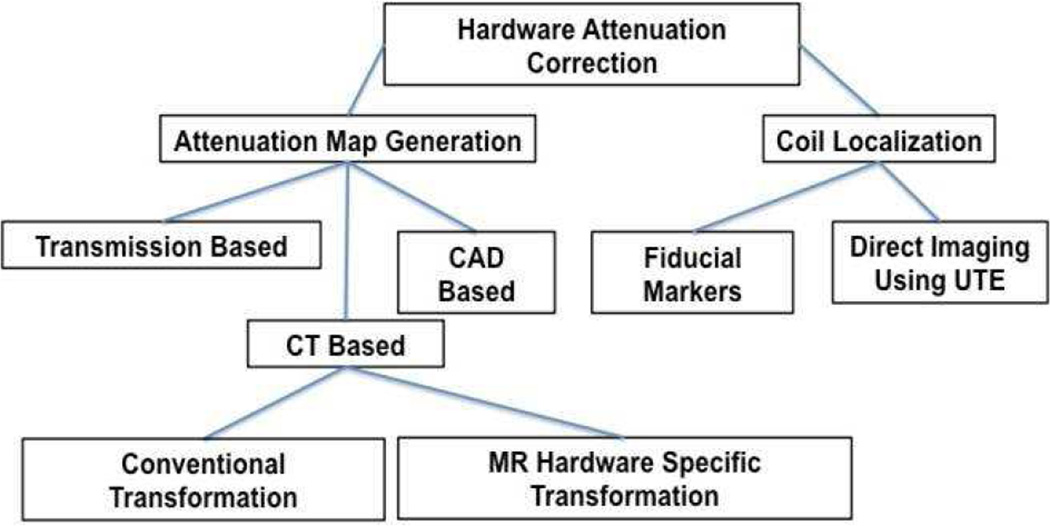
Therefore, AC for MR hardware is a two step problem where 1) an attenuation map must be generated and 2) for flexible coils, the coil must be localized in the PET FOV and the attenuation map must be aligned with the emission data. A summary of the proposed methods is shown below in Figure 3. Details of each method are further discussed in the next sections.
Figure 3.
Summary of the currently proposed method to generate hardware attenuation maps and to localize flexible coils in the PET FOV. Acronyms: Computer-aided design (CAD), Computed Tomography (CT), and ultrashort echo time (UTE).
i) Attenuation Map Generation for MR Coils
a) Transmission based attenuation maps
The gold standard method for generating PET attenuation maps is using transmission based (TX) attenuation maps with a 511keV source28. The calculation of TX attenuation maps is obtained by performing a blank scan without the object in the FOV and a transmission scan with the subject in the FOV. The attenuation correction factors (ACF) are the ratio between the transmission scan and the blank scan, which is converted back to image space28. Typically, transmission attenuation maps are generated using a rotating 511 keV source that has a long half-life such as germanium-68. TX attenuation maps for MR coils and hardware are the standard AC method for the Philips Ingenuity TF PET/MR system23. The attenuation maps are stored as templates and are used for reconstruction whenever a specific part of the coil is within the PET FOV. The authors evaluated the accuracy of this TX attenuation map for the head and found that ignoring the attenuation of the coil resulted in about 15% error23.
In order to provide TX attenuation correction for all objects in the FOV of a sequential PET/MR scanner, a transmission ring was mounted inside the bore of the PET scanner and allowed accurate AC for both the MR coils and the patient29. This method eliminates the need to pre-generate and store templates of the attenuation maps on the scanner and would also provide AC for flexible coils. A drawback is that it requires time-of-flight information during PET acquisitions.
While TX-AC is the gold standard, it suffers from some limitations. PET scanners with a transmission source are generally older systems that are equipped with large-sized detector elements. The resultant spatial resolution of the attenuation map is not high enough in order to capture the structure of the detailed electronics inside the MR coils accurately. Moreover, those scanners are infrequently used clinically.
b) CT based attenuation maps
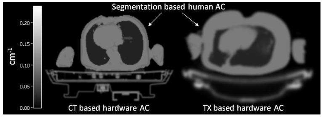
The advent of combined PET/CT prompted the development of CT-based AC (CTAC)30–32. CT imaging is a transmission imaging technique with an X-ray beam that contains photons of various energies from 10–100 KeV31. The Hounsfield units (HU) in CT images must be scaled to match the energy of the PET photons (511 KeV) in order to obtain a suitable AC. This scaling was experimentally measured and is approximated with a linear or a bilinear transformation32. A sample transmission and CT-based attenuation map of the patient beds are shown in Figure 4.
Figure 4.
Sample transmission- and CT-based attenuation maps of the patient table
CTAC has been used for AC of MR coils and hardware in hybrid PET/MR scanners13,14,17,20,33,34 and constitutes the most common and most tested method for producing hardware attenuation maps. This approach for AC is currently used on the Siemens Biograph mMR14,24.
Several studies have evaluated the feasibility of CTAC and have reported contradicting results. For example, Akalan, et al., reported that CTAC was accurate for a breast coil35. Moreover, Paulus, et al., reported successful AC for the body matrix coil14,18. Very recently, Dregely, et al., reported accurate AC using a CT-based map for a new PET/MR optimized breast coil16. On the other hand, MacDonald, et al., reported that CTAC resulted in artifacts and over-correction in the reconstructed PET image using a head and neck coil20. Furthermore, Delso, et al., reported localized errors when attempting to correct for a different head and neck coil using a CT based attenuation map33.
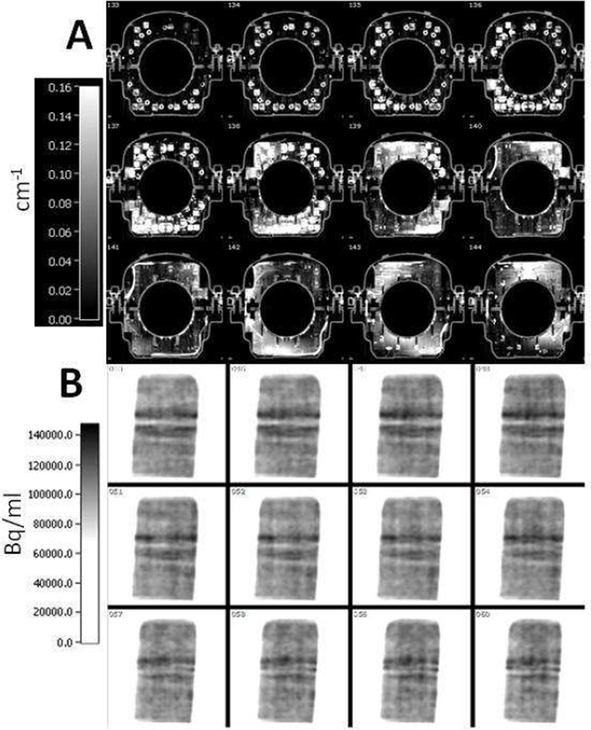
Studies with CTAC concluded that most of the errors emanated from metal and beam hardening artifacts in the attenuation maps33. To address these errors, some studies applied an empirically defined threshold on the CT-based attenuation maps and showed the possible elimination of errors caused by metal and beam hardening artifacts17,35. While these methods could help, Figure 5 shows an example CT-based attenuation map of a knee coil that contains a substantial amount of metal leading to several image artifacts. Consequently, the reconstructed PET image contains artifacts as shown in the bottom panel in Figure 5.
Figure 5.
(A): Sample axial planes of a CT-based attenuation map of a knee coil. High attenuation coefficients and metal artifacts can be seen.
(B): Sample coronal planes from the PET image volume reconstructed with the attenuation map shown in the top panel. Attenuation correction induces image artifacts and quantitative error as can be seen in the image.
Another concern in using CTAC is that the bilinear transformation from HU to PET attenuation coefficients was developed for biological tissues and not for plastics and metals that are used in MR coils and hardware32. A study by Paulus, et al., attempted to develop a new MR-hardware specific transformation from HU to PET attenuation coefficients, and reported minor improvement in the quantification19.
Taken together, CTAC for MR coils seems to be better suited for smaller coils that do not contain much metal or are made from dense materials17,18. For bulky constructions, however, CT-based attenuation maps may contain significant artifacts capable of inducing quantitative errors in the PET image. Those coil designs benefit most from an optimization of their construction.
c) CAD based attenuation maps
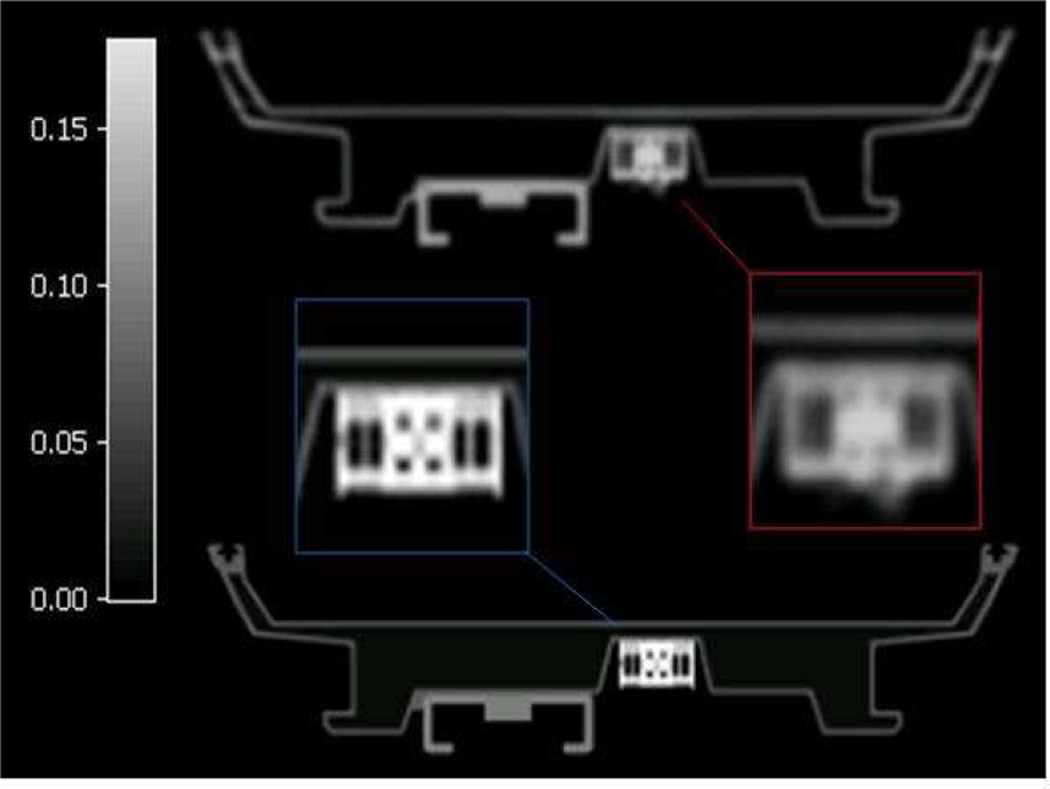
MR coils are generally constructed of a few homogenous materials that have the same attenuation properties. In the design process of such coils computer aided (CAD) drawings are generally used. These CAD drawings of each component of the coil could be described by small volume elements with the appropriate attenuation coefficients assigned34. The advantage of this approach is that the attenuation maps are of high resolution and free from artifacts. The limitation, however, is that this is only feasible for coils with a relatively small number of components. Nevertheless, this AC approach was tested for the patient table of the Biograph mMR, but did not provide improved attenuation correction compared to the system standard CT based attenuation map. A sample CAD based attenuation map as compared to a CT based attenuation map of the mMR patient table is shown in Figure 6.
Figure 6.
Top: sample CT based attenuation map and Bottom: CAD based attenuation map of the mMR patient table. Inserts show some artifacts in the CT based attenuation map.
ii) Localization of the coils in the PET FOV
Rigid coils such as the head and neck coil for example, retain their position from one scan to another and thus the same attenuation map could be used during every scan. Flexible coils, on the other hand change shape and position between and during each scan. Moreover, these coils are invisible in conventional PET/MR imaging and new approaches must be used to localize them accurately. Several groups have investigated the accuracy of AC related to the error in the localization of the coils. It was concluded that while the needed accuracy depends on the coil used, an error of about 3–4 mm is acceptable17,19,33. In the next sections methods to localize coils in the PET FOV are summarized.
d) Markers based localization
The simplest approach to localize MR coils in the FOV is by placing MR visible fiducial markers on their surface14,17,18,36. These markers must also be visible in the attenuation map allowing for the registration of a template attenuation map as shown in Figure 7.
Figure 7.
Overlap between the reference position shown in the fire colormap and the attenuation map to be registered by fiducial markers in the rainbow colormap. The left panel shows the overlap before registration, the middle panel shows the overlap after rigid registration, and the right panel shows the overall after rigid and non-rigid registration using the volume spline algorithm (V-spline).
For flexible coils, the use of non-rigid registration algorithms has been proposed to register the attenuation map to the position of the markers in a particular examination17,18. Using this AC approach, the use of template-based AC for flexible coils could be used in routine clinical scans if the registration procedure is automated. A few studies have evaluated the feasibility of such algorithms and have found acceptable alignments within about 3 mm using a CT-based attenuation map as shown in Figure 7. The advantage of these approaches is that they are simple to implement in the clinical setting. Fiducial markers, however, may interfere with all MR images that are generated with the coil, and the physician must be aware of their presence before reading the data. Furthermore, the markers must remain fixed to the coil which is currently inconvenient for routine use36. Moreover, fiducial marker-based registration utilizes a small set of scattered points in corresponding MR images and thus interpolation between those points must be used to estimate the position of the coil in the FOV. It was shown that significant mis-registration could occur depending on the type of interpolation employed leading to erroneous AC and quantitative errors in the reconstructed PET image17. Taken together, localization of flexible coils by fiducial markers is a feasible, though not ideal technique.
e) UTE based localization
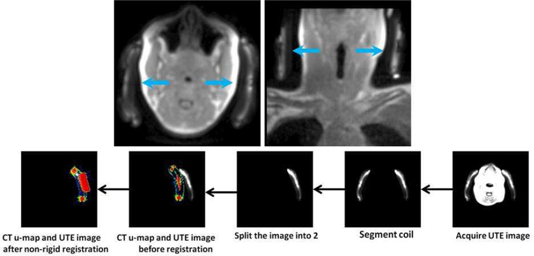
Due to the limitations of fiducial marker based localization of flexible coils, direct imaging of some of the components of the coil using an ultrashort echo time sequence (UTE) has been proposed as a method to localize coils in the PET FOV4,14,26. The UTE sequence is capable of visualizing solid materials such as polymeric plastic and bone37,38. It was shown that AC could be performed by automated non-rigid registration of a template attenuation map to the UTE image making this method a clinically feasible26. This requires, however, that the coil to be constructed specifically from materials that are known to exhibit a signal in the UTE image as shown in Figure 8, top panel. Using non-rigid registration, a CT-based attenuation map can be registered to the UTE image of the coil for accurate AC (Figure 8; lower panel). With UTE-based localization, the total exam time will be extended by about 100 seconds if a small FOV is used as in the case of head and neck imaging for example26. The major advantage of this approach is that the registration could be more robust as compared to a fiducial markers based registration due to the potential high degree of correlation between direct imaging of the entire coil and the attenuation map.
Figure 8.
Top panel. Coils could be imaged using the UTE sequence to localize the coil in the PET FOV. Bottom panel: registration procedure to align a CT based attenuation map.
4) Scatter correction for MR coils
An important physical effect that must be corrected for is the scattering of true coincidence events from interaction with the patient or the imaging hardware. In 3D PET, which is the current data acquisition approach, the scattered events must be subtracted to ensure accurate quantification of measured PET emission data39. Several algorithms have been developed to estimate to amount of scatter such as the Gaussian fitting approaches or the model-based single scatter simulation approach40,41. Scatter correction methods, however, do utilize the attenuation map of objects in the FOV to estimate the amount of scattered events. Consequently, the accuracy of the MR coils and imaging hardware attenuation map could play an important role in the scatter correction step. To the best of our knowledge, no study has evaluated the effect of coil attenuation maps on the estimated scatter. The main reason for this is that it is difficult to experimentally isolate the effect of scatter from attenuation and as a result most studies merge the two effects together. The use of simulations could be a valuable tool to isolate the effect of scatter to study its contribution independently.
5) Data Analysis
Several groups have been studying the effect of MR hardware on quantification using both phantom and clinical data, which led to variety of methods to report and visualize the results. Phantom data, using a phantoms of about the same size as the real body part under investigation, is a useful approach to isolate the effect of the MR hardware. In such experiments a phantom is scanned with and without the MR hardware to generate both a ground truth measurement and a measurement that can be used to study the effect of the MR hardware as well as the feasibility of various data correction approaches. An important aspect in using phantom measurements successfully is to insure that the attenuation map for the phantom contains the correct attenuation coefficients and that it is well aligned with the emission. This issue is relevant for PET/MRIs where the system generated attenuation maps are not designed to work for phantoms42. Data visualization in the phantom scans is often performed either by displaying a difference image or by plotting the mean activity within a ROI over all planes in the phantom, which provides a volumetric evaluation of the attenuation profile rather than just one plane. Instead, using a ROI about the same size of the anatomy of interest is suggested. Moreover, using uniform phantoms might be more desirable versus those that contain hot or cold regions so that the effect of attenuation is isolated from partial volume errors.
Another important aspect is to evaluate the effect of the MR hardware on quantification in clinical studies. Similar data collection is used as in the case of phantoms scans where the subject is scanned with and without the MR hardware under investigation. A limitation to such method in human studies is that there might be a redistribution of the activity in between scans and thus the measurement differences could not be only due to the presence of the MR hardware. Because of this important limitation, interpretation of such data remains difficult.
6) Future Approaches
Some attenuation correction methods have been proposed to correct for attenuation of the patient but could also extended to be used for MR coils and hardware. For example, joint estimation methods that estimate both the attenuation map and the PET image have been gaining popularity recently43,44. In addition, the use of scattered events was recently proposed to estimate the attenuation coefficients in PET/MRI and could be extended to include MR coils and imaging hardware45. Furthermore, placing low activity sources in or around the gantry could also be used for hardware attenuation correction including flexible coils46,47. Finally, one interesting approach to correct for both attenuation and motion is to track fiducial markers placed on the coil, as was discussed before, over the duration of the PET acquisition and incorporating the measured motion into the PET reconstruction48.
7) Conclusions
In this review, we introduced PET imaging and defined some of the problems of hardware attenuation correction for PET/MR. We believe that these problems are currently not well addressed and require further research and development, as well as clinical evaluation. The construction of PET transparent coils has proven insufficient and AC is needed for an accurate quantification. TX-based AC appears to be well suited for AC for MR imaging hardware, however, clinical evaluation in humans has not been reported yet. The lack of availability of transmission scanners has made it difficult for researchers to test their feasibility. CT-based attenuation maps are easily generated, but they could contain artifacts and were shown to produce inconsistent results depending on the construction of the coil. It is possible, however, that the current lack of optimized acquisition, reconstruction, and thresholding parameters for CT-based maps could be the cause of the contradicting findings and must be further studied.
Attenuation correction for flexible coils is still not accounted for in commercial PET/MR scanners though they were shown to produce local errors up to 20%. Registration-based methods have been the most successful in this regard. Fiducial maker-based localization is not ideal clinically and may not produce accurate registration if the markers are placed sparsely or far away from critical components of the coil. Direct imaging of the hardware components using sequences like the UTE requires modification of some coils and increase scan time. With this in mind, progress is still needed in hardware attenuation correction to ensure the quantitative accuracy of PET/MR exams.
Keypoints.
MRI coils and imaging hardware could induce large quantitative errors and image artifacts; attenuation correction is needed.
CT-based and transmission-based attenuation maps might be feasible for small coils, but not large ones.
Attenuation correction for flexible coils that change position and shape between or during imaging sessions is still challenging.
Degree of scattered events due to MR coils and possible corrections has not yet been studied.
Clinical evaluation of the attenuation of coils is challenging and requires more research and development.
Acknowledgements
The authors would like to thank Siemens Healthcare for its technical support. This work is supported in part by a grant from the National Institute of Health, National Heart Lung and Blood Institute (NIH/NHLBI R01 HL071021) (ZAF).
Footnotes
Publisher's Disclaimer: This is a PDF file of an unedited manuscript that has been accepted for publication. As a service to our customers we are providing this early version of the manuscript. The manuscript will undergo copyediting, typesetting, and review of the resulting proof before it is published in its final citable form. Please note that during the production process errors may be discovered which could affect the content, and all legal disclaimers that apply to the journal pertain.
Dr. Faul and Dr. Oesingmann are employed by Siemens Healthcare. Dr. Eldib, Dr. Bini, Dr. Tsoumpas, and Dr. Fayad have nothing to disclose.
REFERENCES
- 1.Wehrl HF, Sauter AW, Divine MR, Pichler BJ. Combined PET/MR: a technology becomes mature. Journal of nuclear medicine : official publication, Society of Nuclear Medicine. 2015 Feb;56(2):165–168. doi: 10.2967/jnumed.114.150318. [DOI] [PubMed] [Google Scholar]
- 2.Fahey FH. Data acquisition in PET imaging. Journal of nuclear medicine technology. 2002 Jun;30(2):39–49. [PubMed] [Google Scholar]
- 3.Blodgett TM, Mehta AS, Mehta AS, Laymon CM, Carney J, Townsend DW. PET/CT artifacts. Clinical imaging. 2011 Jan-Feb;35(1):49–63. doi: 10.1016/j.clinimag.2010.03.001. [DOI] [PMC free article] [PubMed] [Google Scholar]
- 4.Mantlik F, Hofmann M, Werner MK, et al. The effect of patient positioning aids on PET quantification in PET/MR imaging. European journal of nuclear medicine and molecular imaging. 2011 May;38(5):920–929. doi: 10.1007/s00259-010-1721-9. [DOI] [PubMed] [Google Scholar]
- 5.Bini J, Robson PM, Calcagno C, Eldib M, Fayad ZA. Quantitative carotid PET/MR imaging: clinical evaluation of MR-Attenuation correction versus CT-Attenuation correction in (18)F-FDG PET/MR emission data and comparison to PET/CT. American journal of nuclear medicine and molecular imaging. 2015;5(3):293–304. [PMC free article] [PubMed] [Google Scholar]
- 6.Bini J, Eldib M, Robson PM, Calcagno C, Fayad ZA. Simultaneous carotid PET/MR: feasibility and improvement of magnetic resonance-based attenuation correction. The international journal of cardiovascular imaging. 2015 Apr 22; doi: 10.1007/s10554-015-0661-7. [DOI] [PMC free article] [PubMed] [Google Scholar]
- 7.Aitken AP, Giese D, Tsoumpas C, et al. Improved UTE-based attenuation correction for cranial PET-MR using dynamic magnetic field monitoring. Med Phys. 2014 Jan;41(1):012302. doi: 10.1118/1.4837315. [DOI] [PubMed] [Google Scholar]
- 8.Paulus DH, Thorwath D, Schmidt H, Quick HH. Towards integration of PET/MR hybrid imaging into radiation therapy treatment planning. Med Phys. 2014 Jul;41(7):072505. doi: 10.1118/1.4881317. [DOI] [PubMed] [Google Scholar]
- 9.Izquierdo-Garcia D, Catana C. Magnetic resonance imaging-guided attenuation correction of positron emission tomography data in PET/MRI. PET Clinics. 2015 doi: 10.1016/j.cpet.2015.10.002. In press. [DOI] [PMC free article] [PubMed] [Google Scholar]
- 10.Wagenknecht G, Kaiser HJ, Mottaghy FM, Herzog H. MRI for attenuation correction in PET: methods and challenges. Magma. 2013 Feb;26(1):99–113. doi: 10.1007/s10334-012-0353-4. [DOI] [PMC free article] [PubMed] [Google Scholar]
- 11.Hofmann M, Pichler B, Scholkopf B, Beyer T. Towards quantitative PET/MRI: a review of MR-based attenuation correction techniques. European journal of nuclear medicine and molecular imaging. 2009 Mar;36(Suppl 1):S93–S104. doi: 10.1007/s00259-008-1007-7. [DOI] [PubMed] [Google Scholar]
- 12.Herrick PDE, Ansorge RE, Hawkes RC, Sawiak SJ, Stevick JW, Carpenter TA. Radiofrequency coil design for simultaneous PET/MR systems; Paper presented at: Nuclear Science Symposium Conference Record (NSS/MIC), 2010 IEEE; 2010. [Oct. 30 2010–Nov. 6 2010]. [Google Scholar]
- 13.Sander CY, Keil B, Chonde DB, Rosen BR, Catana C, Wald LL. A 31-channel MR brain array coil compatible with positron emission tomography. Magnetic resonance in medicine : official journal of the Society of Magnetic Resonance in Medicine / Society of Magnetic Resonance in Medicine. 2014 Jul 7; doi: 10.1002/mrm.25335. [DOI] [PMC free article] [PubMed] [Google Scholar]
- 14.Paulus DH, Braun H, Aklan B, Quick HH. Simultaneous PET/MR imaging: MR-based attenuation correction of local radiofrequency surface coils. Med Phys. 2012 Jul;39(7):4306–4315. doi: 10.1118/1.4729716. [DOI] [PubMed] [Google Scholar]
- 15.Furst S, Souvatzoglou M, Martinez-Moller A, Schwaiger M, Nekolla SG, Ziegler SI. Impact of flexible body surface coil and patient table on PET quantification and image quality in integrated PET/MR. Nuklearmedizin. Nuclear medicine. 2014;53(3):79–87. doi: 10.3413/Nukmed-0608-13-07. [DOI] [PubMed] [Google Scholar]
- 16.Dregely I, Lanz T, Metz S, et al. A 16-channel MR coil for simultaneous PET/MR imaging in breast cancer. European radiology. 2014 Oct 7; doi: 10.1007/s00330-014-3445-x. [DOI] [PubMed] [Google Scholar]
- 17.Eldib M, Bini J, Calcagno C, Robson PM, Mani V, Fayad ZA. Attenuation correction for flexible magnetic resonance coils in combined magnetic resonance/positron emission tomography imaging. Invest Radiol. 2014 Feb;49(2):63–69. doi: 10.1097/RLI.0b013e3182a530f8. [DOI] [PMC free article] [PubMed] [Google Scholar]
- 18.Kartmann R, Paulus DH, Braun H, et al. Integrated PET/MR imaging: automatic attenuation correction of flexible RF coils. Med Phys. 2013 Aug;40(8):082301. doi: 10.1118/1.4812685. [DOI] [PubMed] [Google Scholar]
- 19.Paulus DH, Tellmann L, Quick HH. Towards improved hardware component attenuation correction in PET/MR hybrid imaging. Phys Med Biol. 2013 Nov 21;58(22):8021–8040. doi: 10.1088/0031-9155/58/22/8021. [DOI] [PubMed] [Google Scholar]
- 20.MacDonald LR, Kohlmyer S, Liu C, Lewellen TK, Kinahan PE. Effects of MR surface coils on PET quantification. Med Phys. 2011 Jun;38(6):2948–2956. doi: 10.1118/1.3583697. [DOI] [PMC free article] [PubMed] [Google Scholar]
- 21.Wollenweber SD, Delso G, Deller T, Goldhaber D, Hullner M, Veit-Haibach P. Characterization of the impact to PET quantification and image quality of an anterior array surface coil for PET/MR imaging. Magma. 2013 Jun 26; doi: 10.1007/s10334-013-0388-1. [DOI] [PubMed] [Google Scholar]
- 22.Tellmann L, Quick HH, Bockisch A, Herzog H, Beyer T. The effect of MR surface coils on PET quantification in whole-body PET/MR: results from a pseudo-PET/MR phantom study. Med Phys. 2011 May;38(5):2795–2805. doi: 10.1118/1.3582699. [DOI] [PubMed] [Google Scholar]
- 23.Bin Z, Pal D, Zhiqiang H, et al. Attenuation correction for MR table and coils for a sequential PET/MR system; Paper presented at: Nuclear Science Symposium Conference Record (NSS/MIC), 2009 IEEE; 2009. [Oct. 24 2009–Nov. 1 2009]. [Google Scholar]
- 24.Eldib M, Faul D, Pawlak J, Doshi N. Verification of the MR components attenuation maps for an MR/PET scanner with simultaneous acquisition. J NUCL MED MEETING ABSTRACTS. 2012 May 1;53(1_MeetingAbstracts):2331-. 2012. [Google Scholar]
- 25.Kolbitsch C, Prieto C, Tsoumpas C, Schaeffter T. A 3D MR-acquisition scheme for nonrigid bulk motion correction in simultaneous PET-MR. Med Phys. 2014 Aug;41(8):082304. doi: 10.1118/1.4890095. [DOI] [PubMed] [Google Scholar]
- 26.Eldib M, Bini J, Robson PM, et al. Markerless attenuation correction for carotid MRI surface receiver coils in combined PET/MR imaging. Phys Med Biol. 2015 Jun 21;60(12):4705–4717. doi: 10.1088/0031-9155/60/12/4705. [DOI] [PMC free article] [PubMed] [Google Scholar]
- 27.Ouyang J, Petibon Y, Huang C, Reese TG, Kolnick AL, Fakhri GE. Quantitative Simultaneous PET-MR Imaging. Journal of medical imaging. 2014 Jun 5;9083:908325. doi: 10.1117/1.JMI.1.3.033502. [DOI] [PMC free article] [PubMed] [Google Scholar]
- 28.Bailey DL. Transmission scanning in emission tomography. European journal of nuclear medicine. 1998 Jul;25(7):774–787. doi: 10.1007/s002590050282. [DOI] [PubMed] [Google Scholar]
- 29.Mollet P, Keereman V, Bini J, Izquierdo-Garcia D, Fayad ZA, Vandenberghe S. Improvement of attenuation correction in time-of-flight PET/MR imaging with a positron-emitting source. Journal of nuclear medicine : official publication, Society of Nuclear Medicine. 2014 Feb;55(2):329–336. doi: 10.2967/jnumed.113.125989. [DOI] [PMC free article] [PubMed] [Google Scholar]
- 30.Kinahan PE, Hasegawa BH, Beyer T. X-ray-based attenuation correction for positron emission tomography/computed tomography scanners. Seminars in nuclear medicine. 2003 Jul;33(3):166–179. doi: 10.1053/snuc.2003.127307. [DOI] [PubMed] [Google Scholar]
- 31.Kinahan PE, Townsend DW, Beyer T, Sashin D. Attenuation correction for a combined 3D PET/CT scanner. Med Phys. 1998 Oct;25(10):2046–2053. doi: 10.1118/1.598392. [DOI] [PubMed] [Google Scholar]
- 32.Carney JP, Townsend DW, Rappoport V, Bendriem B. Method for transforming CT images for attenuation correction in PET/CT imaging. Med Phys. 2006 Apr;33(4):976–983. doi: 10.1118/1.2174132. [DOI] [PubMed] [Google Scholar]
- 33.Delso G, Martinez-Moller A, Bundschuh RA, et al. Evaluation of the attenuation properties of MR equipment for its use in a whole-body PET/MR scanner. Phys Med Biol. 2010 Aug 7;55(15):4361–4374. doi: 10.1088/0031-9155/55/15/011. [DOI] [PubMed] [Google Scholar]
- 34.Eldib M, Faul D, Ladebeck R, Pawlak J, Doshi N. A method for estimating the attenuation correction for the MR hardware of an MR/PET scanner. J NUCL MED MEETING ABSTRACTS. 2012 May 1;53(1_MeetingAbstracts):371-. 2012. [Google Scholar]
- 35.Aklan B, Paulus DH, Wenkel E, et al. Toward simultaneous PET/MR breast imaging: systematic evaluation and integration of a radiofrequency breast coil. Med Phys. 2013 Feb;40(2):024301. doi: 10.1118/1.4788642. [DOI] [PubMed] [Google Scholar]
- 36.Ferguson A, McConathy J, Su Y, Hewing D, Laforest R. Attenuation Effects of MR Headphones During Brain PET/MR Studies. Journal of nuclear medicine technology. 2014 Feb 20;42(2):93–100. doi: 10.2967/jnmt.113.131995. [DOI] [PubMed] [Google Scholar]
- 37.Springer F, Martirosian P, Schwenzer NF, et al. Three-dimensional ultrashort echo time imaging of solid polymers on a 3-Tesla whole-body MRI scanner. Invest Radiol. 2008 Nov;43(11):802–808. doi: 10.1097/RLI.0b013e318188601f. [DOI] [PubMed] [Google Scholar]
- 38.Delso G, Carl M, Wiesinger F, et al. Anatomic evaluation of 3-dimensional ultrashort-echo-time bone maps for PET/MR attenuation correction. Journal of nuclear medicine : official publication, Society of Nuclear Medicine. 2014 May;55(5):780–785. doi: 10.2967/jnumed.113.130880. [DOI] [PubMed] [Google Scholar]
- 39.Ollinger JM. Model-based scatter correction for fully 3D PET. Phys Med Biol. 1996 Jan;41(1):153–176. doi: 10.1088/0031-9155/41/1/012. [DOI] [PubMed] [Google Scholar]
- 40.Cherry SR, Huang SC. Effects of scatter on model parameter estimates in 3D PET studies of the human brain. Nuclear Science, IEEE Transactions on. 1995;42(4):1174–1179. [Google Scholar]
- 41.Markiewicz PJ, Tamal M, Julyan PJ, Hastings DL, Reader AJ. High accuracy multiple scatter modelling for 3D whole body PET. Phys Med Biol. 2007 Feb 7;52(3):829–847. doi: 10.1088/0031-9155/52/3/021. [DOI] [PubMed] [Google Scholar]
- 42.Ziegler S, Braun H, Ritt P, Hocke C, Kuwert T, Quick HH. Systematic evaluation of phantom fluids for simultaneous PET/MR hybrid imaging. Journal of nuclear medicine : official publication, Society of Nuclear Medicine. 2013 Aug;54(8):1464–1471. doi: 10.2967/jnumed.112.116376. [DOI] [PubMed] [Google Scholar]
- 43.Mehranian A, Zaidi H. Joint estimation of activity and attenuation in whole-body TOF PET/MRI using constrained Gaussian mixture models. Medical Imaging, IEEE Transactions on. 2015;PP(99):1–1. doi: 10.1109/TMI.2015.2409157. [DOI] [PubMed] [Google Scholar]
- 44.Mehranian A, Zaidi H. Emission-based estimation of lung attenuation coefficients for attenuation correction in time-of-flight PET/MR. Phys Med Biol. 2015 Jun 21;60(12):4813–4833. doi: 10.1088/0031-9155/60/12/4813. [DOI] [PubMed] [Google Scholar]
- 45.Berker Y, Kiessling F, Schulz V. Scattered PET data for attenuation-map reconstruction in PET/MRI. Medical Physics. 2014;41(10):102502. doi: 10.1118/1.4894818. [DOI] [PubMed] [Google Scholar]
- 46.Watson C. Imaging the attenuation coefficients of positron beams in matter: positron attenuation tomography. EJNMMI Physics. 2015;2(Suppl 1):A20. doi: 10.1186/2197-7364-2-S1-A20. [DOI] [PMC free article] [PubMed] [Google Scholar]
- 47.Watson CC, Eriksson L, Kolb A. Physics and applications of positron beams in an integrated PET/MR. Phys Med Biol. 2013 Feb 7;58(3):L1–L12. doi: 10.1088/0031-9155/58/3/L1. [DOI] [PubMed] [Google Scholar]
- 48.Huang C, Ackerman JL, Petibon Y, et al. Motion compensation for brain PET imaging using wireless MR active markers in simultaneous PET-MR: phantom and non-human primate studies. NeuroImage. 2014 May 1;91:129–137. doi: 10.1016/j.neuroimage.2013.12.061. [DOI] [PMC free article] [PubMed] [Google Scholar]


