Abstract
Usually, origami-based morphing structures are designed on the premise of ‘rigid folding’, i.e. the facets and fold lines of origami can be replaced with rigid panels and ideal hinges, respectively. From a structural mechanics viewpoint, some rigid-foldable origami models are overconstrained and have negative degrees of freedom (d.f.). In these cases, the singularity in crease patterns guarantees their rigid foldability. This study presents a new method for designing self-deploying origami using the geometrically misaligned creases. In this method, some facets are replaced by ‘holes’ such that the systems become a 1-d.f. mechanism. These perforated origami models can be folded and unfolded similar to rigid-foldable (without misalignment) models because of their d.f. focusing on the removed facets, the holes will deform according to the motion of the frame of the remaining parts. In the proposed method, these holes are filled with elastic parts and store elastic energy for self-deployment. First, a new extended rigid-folding simulation technique is proposed to estimate the deformation of the holes. Next, the proposed method is applied on arbitrary-size quadrilateral mesh origami. Finally, by using the finite-element method, the authors conduct numerical simulations and confirm the deployment capabilities of the models.
Keywords: deployable structure, origami, Miura-ori, rigid folding
1. Introduction
Represented by Miura-ori and the double corrugation surface (DCS), origami offers creative solutions for folding and deploying large structures and has inspired the creation of various types of deployable structures [1]. Scientific attention towards origami was directed by geometricians and mathematicians. After the pioneering work of Lang's ‘Treemaker’ [2], researchers proposed various computational methods [3,4] for crease-pattern designing. Although some restrictions about foldable shapes remain, these works are considered to have enabled the creation of crease patterns for arbitrarily shaped origami. In parallel to the works on new crease-pattern designing, researchers have also addressed the remaining problem of ‘How to fold’ from an engineering perspective. Hawkes et al. [5] reported the development of a composite material sheet that can fold itself by electrical heating of a shape memory alloy (SMA) hinge. Liu et al. [6] proposed a self-folding origami made of sheets of optically transparent, prestrained polystyrene that shrinks in-plane when heated uniformly. A similar concept is found in the self-folding shape memory composites proposed by Tolley et al. [7], which are activated with uniform heating in an oven. These actuation mechanisms are designed to fold from a flat sheet to a three-dimensional shape, but it is also possible to use them for deploying from a fully stowed to a fully deployed state. The mechanisms in these previous studies were realized by morphing hinge parts. This is reasonable because the materials mostly deform along the fold lines. However, controlling the angle between two facets requires a complex mechanical system or special materials such as plate-shaped SMAs or shape memory polymers, which leads to increased manufacturing cost and reliability degradation.
As an alternative solution for self-folding/unfolding origami, the authors propose the application of elastic behaviour found in some origami models [8]. Usually, origami-based structures are designed on the premise of ‘rigid foldability’, i.e. the facets and fold lines of origami can be replaced with rigid panels and ideal hinges, respectively. Wu & You [9] proposed a new crease pattern that allows a tall box-shaped bag with a rectangular base to be rigidly folded flat. Yasuda et al. [10] examine the folding behaviour of Tachi–Miura polyhedron (TMP) bellows, which is known as a rigid-foldable structure by theoretical and experimental methods. From an engineering standpoint, rigid origami is useful because it provides a solution to folding rigid thin-walled structures. However, ideal rigid folding is hard to achieve in real structures; therefore, almost every act of folding and unfolding is accompanied by elastic deformations. These deformations emerge as stretching and shrinkage of fold lines, fold line drifts and out-of-plane deformation of facets [11–13]. Guest & Pellegrino [14–16] examined the folding properties of triangulated cylinders by using a computational approach and experiments. Schenk & Guest [17] proposed the folded textures sheets model with egg-box and Miura-ori patterns and performed a stiffness analysis by using a pin-jointed truss framework without the expense of a full finite-element analysis. If the elastic behaviours of these origami models can be used as the actuator for deployment, the requirement for complex mechanical systems or special materials for the origami-based deployable structures will be overcome. Excellent examples of this concept are found in the wings of insects. Entomologists have pointed out that certain species of Coleoptera and Dermaptera use the intrinsic elasticity of their wings for folding and unfolding them [18–20].
This paper illustrates a new strategy for designing self-deploying origami actuated by the elastic energy stored in its own facets or simple formed actuators such as springs. In some origami models, rigid foldability is guaranteed by a singularity of crease patterns regardless of their mechanical degree of freedom (d.f.). This special rigid foldability is investigated in quadrilateral mesh origami by Tachi [21]. Because of singularity, for some rigid-origami models that have redundant constraints, the omission of facets can be tolerated. These ‘hollow facets’ will maintain their shape during the folding process in rigid-foldable crease patterns. However, if misalignments are introduced in the creases, they should deform because of the loss of structural singularity. The proposed method uses these hollow facets as actuators or as storage for elastic energy for deployment. The basic concept of this self-deploying origami was validated in a simple nine-hinged plate model [8]. However, the previous work has had limitations in the size and geometry of its base origami models. In this paper, the proposed method is extended to a generalized quadrilateral mesh origami with arbitrary size and geometry.
The outline of the paper is as follows. First, the concept of the proposed self-deploying origami is explained using quadrilateral mesh origami. The second part illustrates extended rigid-origami simulation techniques that can treat the rigid-origami model with holes and ball joints. This part also describes the problem of the mountain–valley assignment in numerical calculations. In the third part, the techniques are used to find a proper misalignment to provide an ideal relationship between facet deformation and folding/unfolding of whole structures, and crease-pattern designing methods are revealed. The last section details the numerical simulations using the finite-element method and confirms the deploying capabilities of the models.
2. Self-deploying origami with misaligned crease patterns
This study considers quadrilateral mesh origami, such as Miura-ori and DCS, as shown in figure 1a,b. Some quadrilateral mesh origami possesses rigid foldability even in the overconstrained condition, which implies that the number of constraints exceeds the total d.f. of the mechanism. Tachi investigated the geometric condition for enabling rigid motion in quadrilateral mesh origami and created the various crease patterns (figure 2) [21]. This mechanically paradoxical rigid foldability is caused by a singularity of crease patterns. From an engineering standpoint, this overconstrained condition benefits deployable structures. Because of the redundant construction, the structure tolerates omission or destruction of facets; it maintains the inextensional mechanisms until its d.f. exceeds one and can be deployed according to the initially determined movement.
Figure 1.
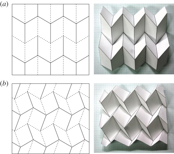
Examples of quadrilateral mesh origami models. (a) Miura-ori and (b) DCS.
Figure 2.
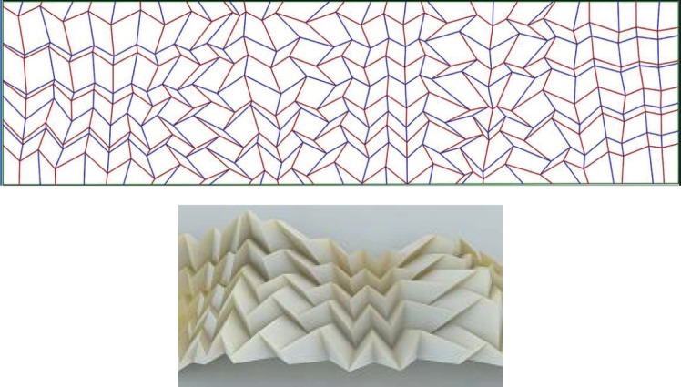
Rigid-foldable generalized quadrilateral mesh origami (courtesy of Tomohiro Tachi) [19]. (Online version in colour.)
The proposed method uses these structurally overconstrained origami models. First, some facets are intentionally removed from the model to achieve 1-d.f. The space-frame truss model is used to calculate the d.f. Under the assumption of rigid folding, the origami model shown in figure 3a is equivalent to the space-frame truss model shown in figure 3b. In the truss model, all fold lines and vertices are replaced with truss members and ball joints, respectively, and two additional trusses are added to the diagonal lines of each quadrilateral facet. The stability of the space-frame trusses can be determined by the d.f. expressed by the following equation:
| 2.1 |
where j is the total number of joints, t is the total number of truss members and r is the number of reactions (generally equal to six in a three-dimensional structure). Using this equation, the truss of figure 3b is determined as overconstrained: t=72,j=25, r=6, then d.f.=−3). In order to provide a 1-d.f. mechanism, four redundant trusses should be removed. There are various pattern options for selecting the trusses to be removed. This study treats the restrictions with omission of facets, so truss members are always removed by the set of two diagonal lines as shown in figure 3c. In addition, two adjacent facets may not be removed at the same time. This is necessary for the simple expression of deformations of hollow facets, which can be achieved by simple actuators.
Figure 3.
Structural stabilities of 4×4 Miura-ori model. (a) Origami model. (b) Space-frame truss model in overconstrained condition (d.f.=−3). (c) Space flame truss model with 1-d.f.
Figure 4 shows the 1-d.f. origami model with two hollow facets A and B. If the crease pattern has the aforementioned peculiar rigid foldability, the hollow facets will not deform during folding/unfolding of the whole structure (figure 4a). Next small misalignments are introduced in the crease lines. The sizes of these misalignments should be small enough to not cause interferences with facets during the deployment. Obviously, these misalignments break crease-pattern-dependent rigid foldability. However, because of its 1-d.f. mechanism, achieved by the existence of hollow facets, the structure can be folded/unfolded the same way as with the correct (without misalignment) crease model. The important difference is that hollow facets with a misaligned crease pattern will deform during folding/unfolding of the whole structure (figure 4b), unlike with the correct crease model. In the proposed method, deployment of the structures is controlled by the deformation of the hollow facets. This study employed the lengths of two diagonal lines of the square frame as the simple expressions for the deformations. If the lengths correspond one-to-one with the progression of deployment of the whole structure, the folding and unfolding of the structure can be controlled only by changing the diagonal lines. The design process for this self-deploying origami comprised searching for the proper misalignment that provided an ideal history of diagonal lines. In the properly misaligned crease patterns, the total strain energy in the actuating elements must be monotonically decreasing to ensure deployment. This paper discusses the simplest case where all these diagonal lines monotonically increased or decreased during the folding/unfolding process, thus indicating that only simply extending or shrinking actuators were sufficient to provide the necessary deformation on the hollow facets to achieve self-deployment.
Figure 4.
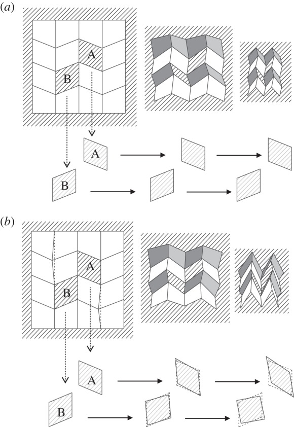
Deformations of hollow facets. (a) In correct crease patterns. (b) Misaligned crease patterns.
3. Extended rigid-origami simulation techniques
(a). Equations of origami kinematics with holes
To find the suitably misaligned crease patterns, a method to calculate the movements of the frames of hollow facets (determined by the edges of remained facets) is necessary. In the kinematic analysis of complex mechanisms, the matrix method using the Denavit–Hartenberg notation is classically used [22]. Belcastro & Hull [23] proposed the modelling method of the kinematics in paper folding by using affine transformations, which is a strip-down version of the matrix method. Based on this modelling, Tachi proposed a system for simulating the folding motion of origami by calculating the trajectory by a projection to the constrained space on the basis of a rigid-origami model [24,25]. The rigid-origami simulation technique is the specialized kinematic analysis method for origami and enables us to directly calculate the folding motion from given crease patterns defined on a plane. However, because of the hollow facets and ball-joint parts, it is impossible to apply these techniques on the perforated origami models discussed in this paper. This section illustrates the extension of rigid-origami simulation techniques that can consider such unusual origami models.
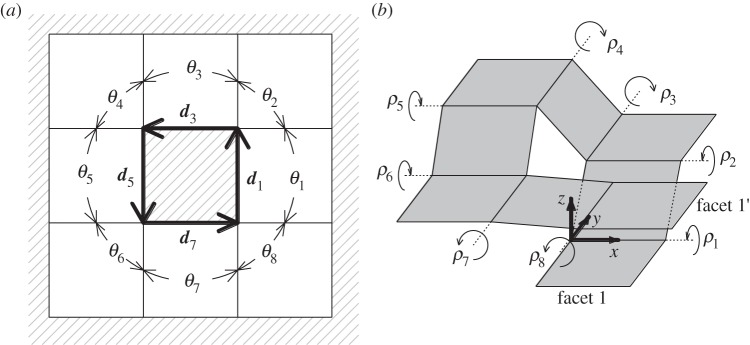
In a rigid-foldable origami model, the position and attitude of facets at a certain moment of the folding process can be represented by the folding angles between two connected facets. In fact, in the case of 1-d.f. origami, the number of independent folding angles is always one. So if one folding angle is fixed, the others can be determined subsequently by the geometrical restrictions. The rigid-origami simulation techniques provide the generalized method for calculating all folding angles during the folding process in the given crease patterns, and they consist of the equation derivations for geometrical restrictions and the method for solving them. In a normal origami model, all necessary equations are obtained from the restrictions around the vertices. Figure 5 shows a vertex defined by n number of sector angles θ1–θn. The equations that the folding angles ρ1,…,ρn should meet are expressed as follows, according to [25].
| 3.1 |
and
| 3.2 |
Because χ1,…,χn represents rotation by each folding line, equation (3.1) can be translated as the condition in which one coordinate system returns to the initial attitude after being sequentially rotated about each folding line. As R is a rotational matrix, this fundamentally reduces to three scalar equations by using elements as follows:
| 3.3 |
Tachi [25] also addresses the case of the origami model with isolated holes. This configuration is expressed by sector angles θ1–θn and edge vectors d1∼dn, as shown in figure 6. Note that the sector angles are defined between the adjoining two folding lines. Then, the folding angles ρ1,…,ρn should satisfy following equations:
| 3.4 |
and
| 3.5 |
Here, di represents an edge line vector around a hole on each facet axis.
Figure 5.
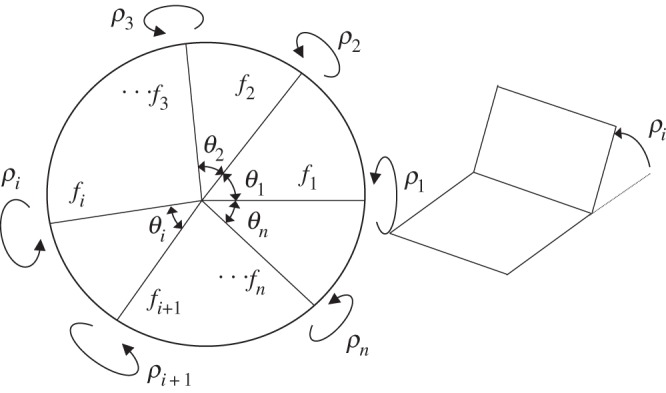
Restriction emerged around a vertex. A folding angle is defined as the right figure: complete unfolding is represented as ρi=0. Positive direction (Valley folding) is defined the right-handed screw direction from considered vertex outwards.
Figure 6.
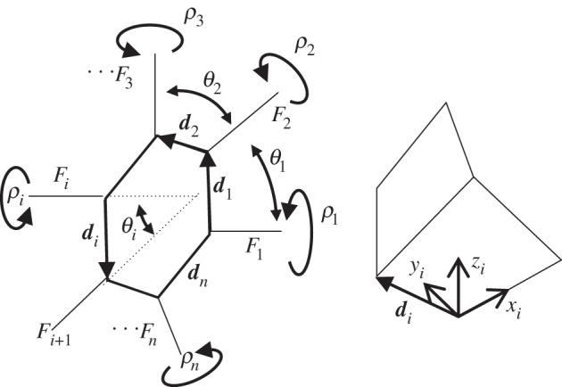
Restriction emerged around a hole. Each hole provides six equations.
The unusual origami models discussed in this paper include connected holes and ball-joint facets, so the above conditions are insufficient to express all restrictions. Therefore, an extended rigid-origami simulation technique is presented that provides a universal method to simulate the mechanisms for origami with hollow facets.
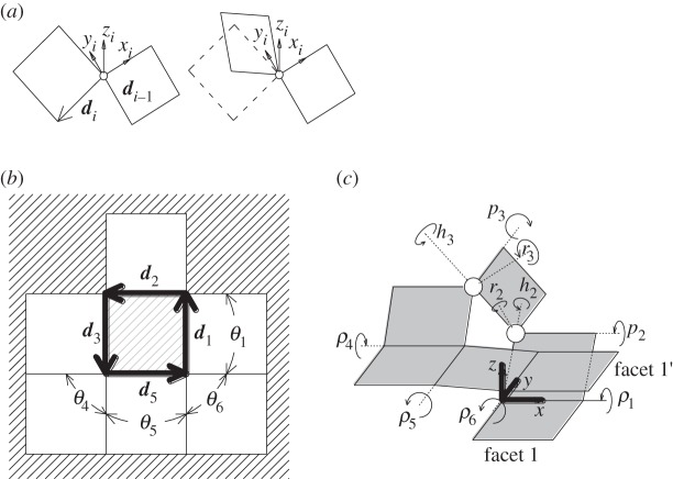
The restrictions around an isolated hole (equations (3.4) and (3.5)) can be interpreted as equivalent to a robot arm manipulation problem. Considering facets and folding lines as arms and pin joints, figure 7a can be translated as the robot arm model shown in figure 7b. To close a loop around the hole, the arm tip of facet-1′ should be matched with original facet-1. Equations (3.4) and (3.5) represent the conditions about the attitude and the position of facet-1′, respectively. Similarly, a hole with ball-joint facets is represented as the robot arm problem shown in figure 8. In order to treat this problem, the extended technique employs new unknowns on the ball-joint parts. The relative attitude between two facets connected with ball joints is expressed by Euler angles (ri,pi,hi) as shown in figure 8a. Including these unknowns, the rotation matrixes on a folding line and a ball joint are represented as follows:
| 3.6 |
and
| 3.7 |
By using these rotational matrixes, the restriction around holes with ball joints can be represented by the same forms of equations (3.4) and (3.5). The folding lines and ball joints should be numbered serially around a hole like figure 8c, and applied equations (3.6) and (3.7), respectively.
Figure 7.
Equivalent problem on robot arm manipulation with pin joints (d2, d4, d6 and d8 are considered as zero in this case).
Figure 8.
Equivalent problem on robot arm manipulation with pin joints and ball joints. (a) Euler angles (ri,pi,hi) are defined by the rotation angles around the zi-axis, xi-axis and yi-axis on connecting facets. d4 and d6 are considered as zero in this case.
These equations can represent all restrictions on unusual origami models with hollow facets. In the case of figure 4, the crease pattern has 16 folding lines and one ball joint, so the number of unknowns is determined to be 19. Geometrical restrictions are obtained from two vertices and two holes, which results in 18 nonlinear equations (figure 9).
Figure 9.
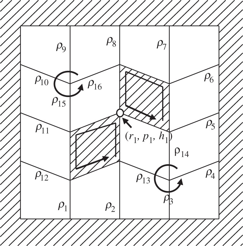
The unknowns and restrictions in 4×4 Miura-ori model with two hollow facets.
(b). Numerical calculations
In the proposed models, the nonlinear simultaneous equations obtained from the aforementioned restrictions always have an additional unknown because of their 1-d.f. mechanism. Further, when one folding angle is specified, the simultaneous equation can be solved using a numerical solution. First, one folding angle is selected as a pilot for folding. Starting from 0 [degree], indicating completely unfolded, the pilot angle is increased gradually and the other folding angles are calculated using a numerical solution. Repeating this process provides the folding movement for all facets during the folding process.
Using an iterative algorithm such as the Newton–Raphson method used in this study, it is not difficult to solve the aforementioned nonlinear simultaneous equations. However, a problem peculiar to origami simulation is found in the generation of objective folding modes. Generally, a rigid-foldable origami has multiple mountain–valley assignment patterns which can cause inextensional mechanisms. These mountain–valley assignments are satisfied in the nonlinear simultaneous equations derived in the last subsection. However, in incorrect folding modes, the structure cannot be completely folded because of the conflict of facets. Figure 10 shows the four different possible mountain–valley assignments in two connected 4-degree vertices. Which mountain–valley assignment occurs as the solution is determined by the initial values of iterative calculations. The problem is that all possible mountain–valley assignments exist in close proximity in the solution space at the starting point of the rigid-folding simulation. This is because a valley crease easily changes to a mountain crease (or vice a versa) in the neighbourhood of a completely unfolded state. In order to converge a solution to a proper mountain–valley assignment, iterative calculations should be started using proper initial values close to the solution of the correct mountain–valley assignment. However, the increasing number of unknowns and the existence of crease pattern misalignment make this problem more difficult; therefore, it is very hard to seek proper initial values by using a simple trial-and-error method.
Figure 10.
Possible mountain–valley assignments of connected two 4-degree vertexes.
The authors propose the following methods for solving this problem. In the case of usual rigid-foldable origami models without misalignments, folding angles can be calculated by other easy methods. For example, if a crease pattern consists of only 4-degree vertices, such as with quadrilateral mesh origami, all folding angles can be calculated from a given pilot angle using symbolic methodology. This technique is known as the sequential method [8]. In the proposed methods, the initial values for first step are calculated from the base model, i.e. the correct crease pattern before it is misaligned and facets removed. The discussed misalignments are so small that the solutions in the correct models and in the misaligned one are thought to be similar. Then, using the solutions from the correct model as the initial values can make the solutions converge for the desired mountain–valley assignment.
4. Crease-pattern design
The extended rigid-origami simulation technique can demonstrate the folding process of the unusual origami model with holes and ball joints and subsequently reveal the deformation of the hollow facets. This section explains the process of designing misaligned crease patterns that can be used as self-deploying origami. In a quadrilateral mesh origami with m×n panels, the d.f. is calculated as −(m−2)(n−2)+1 using the space-frame truss model (figure 11). This means that additional (m−2)(n−2) restrictions have to be removed to achieve a 1-d.f. mechanism. For simplicity, this paper considers the case in which at least one of m and n is an even number. As mentioned in the previous section, removing one facet reduces two restrictions. Then, the number of hollow facets that confer a 1-d.f. mechanism can be calculated as (m−2)(n−2)/2. This removal pattern has numerous variations. To achieve a smooth deployment, it is desired that deployment forces are widely dispersed on the whole structure. Therefore, we propose the methods as shown in figure 12a. As an example, 6×6 Miura-ori crease patterns are considered. Except for the perimeter panels, the inner panels are removed with a checkerboard pattern. This removal pattern can always confer a 1-d.f. mechanism. In the example of figure 12a, the d.f. is calculated as −15, so eight hollow facets are introduced to achieve a 1-d.f. mechanism.
Figure 11.
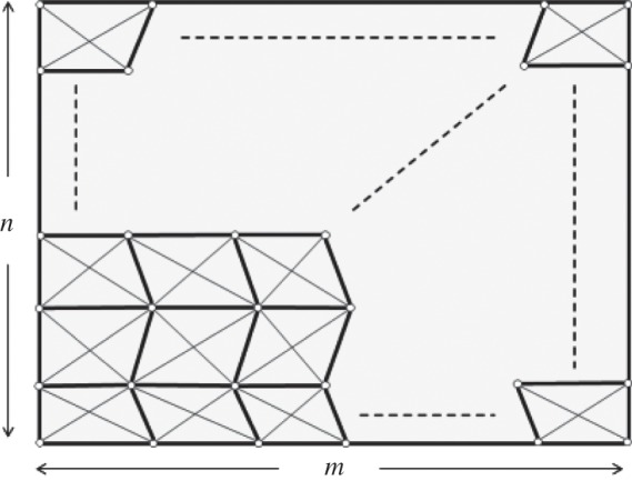
Generalized quadrilateral mesh origami with m×n panels. The total number of joints j and the total number of truss members t are calculated as mn+m+n+1 and 4 mn+m+n. Then, the d.f. is calculated as −(m− 2)(n−2)+1 from equation (2.1).
Figure 12.
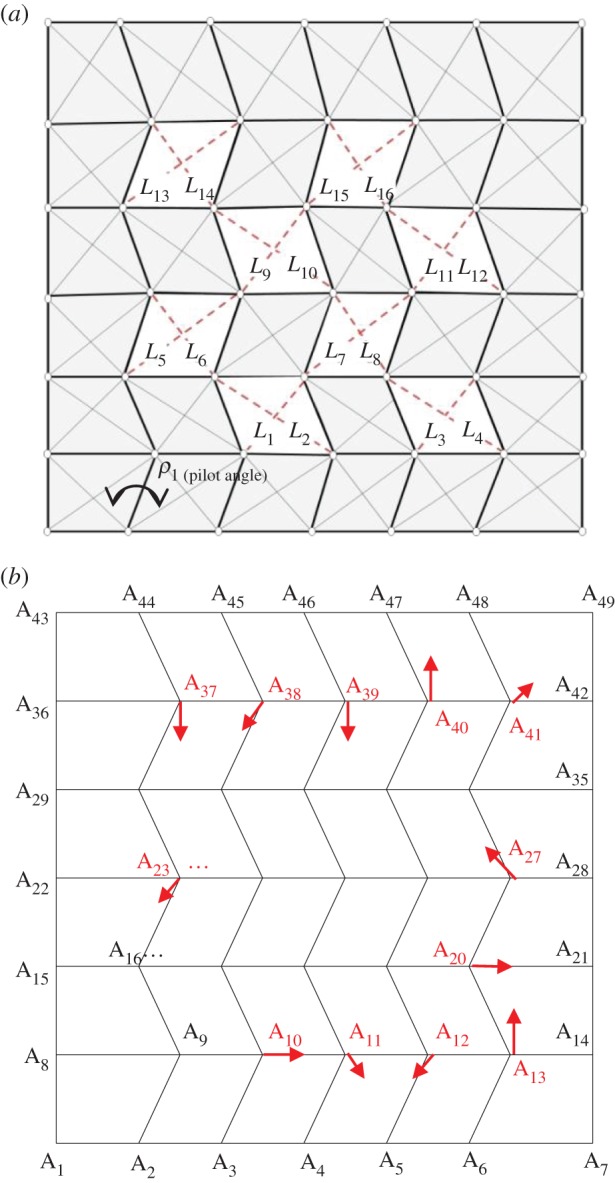
Designing process for self-deploying origami. (a) 1-d.f. model with eight hollow facets. Their deformations are represented by the lengths of their diagonal lines, L1–L16. (b) A Miura-ori base model with misaligned vertexes A10–A13, A20, A23, A27 and A37−41. (Online version in colour.)
To cause deformation on the hollow facets in the folding process, misalignments are introduced in the crease patterns. The extended rigid-origami simulation techniques are conducted on these misaligned and perforated origami models. The model shown in figure 12 consists of 28 folding lines and nine ball joints, and hence has 55 unknowns. The necessary equations are obtained from two vertices and eight holes. Each vertex and hole provides three and six equations, respectively, so 54 nonlinear equations are developed from equations (3.1)–(3.7). First, in 55 unknowns ρ1–ρ55, only ρ1 is selected as a pilot angle and set at 1.0°. This example uses the angle of A9A2 as the pilot angle ρ1(figure 13). The remaining 54 unknowns are calculated from the above-mentioned 54 nonlinear equations using the Newton–Raphson method. The initial values of ρ2–ρ55 are given by the results of the rigid-origami simulation of the correct model using sequential methods. Solutions obtained at ρ1=1.0 are used as the next initial values of the calculation at ρ1=2.0°. Repeating this process, the histories of diagonal line lengths are recorded until ρ1=180°. The calculations are conducted by Matlab®.
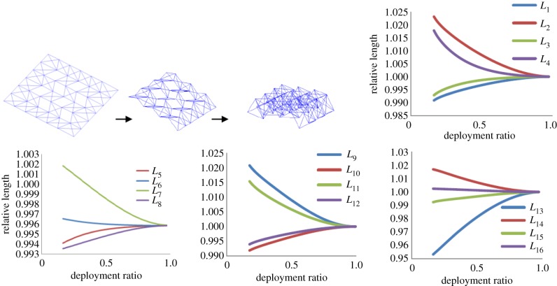
Figure 13.
The result of the extended rigid-origami simulations. The folding process is visualized by space-frame truss model (top left). The graphs show the history of the length of diagonal lines during the folding process. The relative length is defined as the ratio of the current length of each diagonal line to the original length at the completely unfolded condition. The degree of deployment is represented by the pilot angle ρ1. The transverse axes of the graphs use the deployment ratio defined as D=(180−ρ1)/180.
This study uses a randomized approach to search for a proper misalignment. All vertices except for the ones on the perimeters are given randomized misalignment. In each case, the programme determines whether the misalignment is proper for simple self-deployment, i.e. all deformation histories of the hollow facets (diagonal lines L1–L16) are monotonic increase or decrease. The misalignments are selected from +0.4, 0.0 and −0.4 at random and given to x- and y-coordinates of each vertex. This amplitude corresponds to 0.5% of the width of parallel creases in the Miura-ori pattern.
Using this method, we can find several crease patterns with proper misalignments, one example of which is shown in table 1, in the form of vertices data. Vertices A10–A13, A20, A23, A27 and A37–A41 are slightly shifted from correct pattern. These misaligned vertices are followed by an asterisk in table 1. Small allows in figure 12b also express the shift directions of misaligned vertices. In the resulting extended rigid-origami simulation, it is confirmed that valley and mountain creases are assigned correctly according to a Miura-ori pattern as shown in top left of figure 13. The deformation histories of each diagonal line are shown in figure 13, which are of monotonic increase or decrease. This implies that self-deployment of this model is achieved by simply extending or shrinking the spring set on these diagonal lines. According to figure 13, these springs required approximately ±2–5% elongations in the deployment.
Table 1.
Vertices data of figure 12 model. Misaligned vertices are followed by an asterisk.
| vertex | x | y | vertex | x | y |
|---|---|---|---|---|---|
| A1 | 0 | 0 | A25 | 280 | 240 |
| A2 | 80 | 0 | A26 | 360 | 240 |
| A3 | 160 | 0 | *A27 | 439.6 | 240.4 |
| A4 | 240 | 0 | A28 | 520 | 240 |
| A5 | 320 | 0 | A29 | 0 | 320 |
| A6 | 400 | 0 | A30 | 80 | 320 |
| A7 | 520 | 0 | A31 | 160 | 320 |
| A8 | 0 | 80 | A32 | 240 | 320 |
| A9 | 120 | 80 | A33 | 320 | 320 |
| *A10 | 200.4 | 80 | A34 | 400 | 320 |
| *A11 | 279.6 | 80.4 | A35 | 520 | 320 |
| *A12 | 359.6 | 79.6 | A36 | 0 | 400 |
| *A13 | 440 | 80.4 | *A37 | 120 | 399.6 |
| A14 | 520 | 80 | *A38 | 199.6 | 399.6 |
| A15 | 0 | 160 | *A39 | 280 | 399.6 |
| A16 | 80 | 160 | *A40 | 360 | 400.4 |
| A17 | 160 | 160 | *A41 | 440.4 | 400.4 |
| A18 | 240 | 160 | *A42 | 520 | 400 |
| A19 | 320 | 160 | A43 | 0 | 480 |
| *A20 | 400.4 | 160 | A44 | 80 | 480 |
| A21 | 520 | 160 | A45 | 160 | 480 |
| A22 | 0 | 240 | A46 | 240 | 480 |
| *A23 | 119.6 | 239.6 | A47 | 320 | 480 |
| A24 | 200 | 240 | A48 | 400 | 480 |
| A49 | 520 | 480 |
5. Deployment simulation using LS-DYNA
In the discussions in the above sections, the facets were assumed to be the rigid plates, and the deploying motions were calculated only by geometrical considerations. However, a real plate has a finite stiffness and, therefore, deforms during the deploying process. These facet deformations may lead to undesirable motions and eventual locking up of the mechanism into some locally stabilizing points. In this section, the proposed structure was modelled by the elastic plates and ideal joints having no friction. A commercially available finite-element method package, LS-DYNA®, was used to conduct a numerical simulation and to examine that the structure could accomplish the complete deployment as expected. We have also investigated the strain distribution in the facets during deployment.
The numerical model is a 1 mm aluminium alloy plate (E=70 (GPa), ν=0.33, ρ=2.7 (g cm−3)) of size 520 × 480 mm in complete deployment. The crease pattern is based on the model shown in figure 12 and table 1. According to figure 13b–d, elastic spring elements (k=50 N mm−1) is inserted on diagonal lines and the initial offsets are provided properly such that the desired forces are caused. Each facet is made of 400 four-node elastic shell elements. At a fold line where the edges of two facets meet, nodes on each edge line share the same translational motion in order to model the hinges. Focusing on the deploying motion, the numerical model is started in a 20% folded condition.
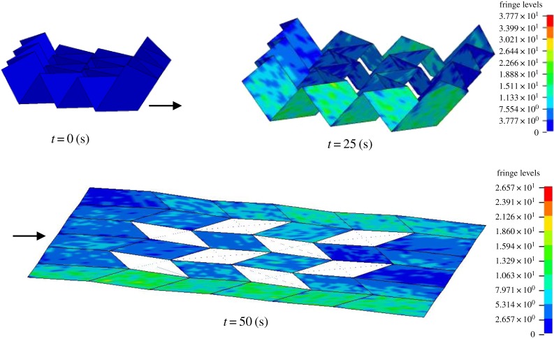
Figure 14 shows the result of a deployment simulation. As expected in the calculation by the extended rigid-origami simulation, simple spring elements impart complete deployment. Figure 14 uses colour contours to indicate von Mises stress. Representative aerospace aluminium alloys such as 2024, 6061 and 7075 have the proof stresses of about 240–500 MPa (e.g. 269–276 MPa in 2024-T3, 241 MPa in 6061-T6, 434–503 MPa in 7075-T6). Throughout the simulation, the maximum stress is about 34 MPa, which corresponds to 7–14% of the proof stresses of commonly used aerospace aluminium alloys. This figure shows that the strain was concentrated in the perimeter panels during the deployment. The results indicated that these panels required higher rigidity and strength than that required in the inner panels. This strain concentration could also be observed in the end of the simulations. In theory, the elastic energy of the entire structure becomes zero in the completely deployed condition, and, thus, the angles on the folding lines were expected to have minor deviations from 180°. However, based on these figures, these deviations were negligibly small compared with the size of the structures.
Figure 14.
Deployment simulation using LS-DYNA®. Colour indicates von Mises stress.
6. Discussion and conclusion
This paper illustrates a new concept for self-deploying origami based on misaligned crease patterns. The advantage of the proposed method is that it requires only a simple actuator that can shrink or expand in length between two vertices. In this paper, simple spring elements on diagonal lines are employed as actuators, but other actuators such as ball screws, wire with a winder and SMA wires can also be used. These active actuators enable deployment at arbitrary timing. In addition, the proposed method can coordinate the necessary displacements required in actuators only by changing the amplitude of misalignments. With respect to the power of the actuation force, we have to consider the small mechanical advantage of the proposed mechanism. Compared with the displacements of the actuators (diagonal lines in the cut-out facets), the deformation of the whole structure is very large. This means that a lot of force is required for the actuators, even if the resistive forces to the deployment (e.g. the friction forces in the joints) are small. Owing to these characteristics, high-power but small-displacement actuators represented by an SMA actuator and piezo actuator were thought to be suitable for the proposed technique. In the case of figure 13, the necessary displacements in the actuators were approximately ±2–5% elongations of the lengths of the diagonal lines. Since the maximum recovery strain of the generally used Ti–Ni SMA wires was approximately 8%, they could be used as a workable option for the actuator.
To determine the concrete performances required for the actuators, a quantitative evaluation of the resistive forces is required. For this purpose, the prototypes are currently under development for experimental analysis. The production difficulties are summarized in designing pin joints and balls joints. The proposed method controls the movements of the structures by small misalignments, so there is a possibility that backlashes in these joints interfere with the deployments. To prevent this problem, the use of precisely made joints is required after clarifying the allowable backlashes. Regarding the design of the joints, we must also consider the effect of plate thickness. The folding of thick panels connected by mechanical hinges causes the collisions of plates on the valley folding lines, and offsetting the rotation axis deviates the mechanism from predefined rigid-origami kinematics. Researchers such as Tachi [26] and Chen et al. [27] have investigated these problems and proposed some techniques for origami of thick panels. Applying these techniques enables us to manufacture the prototype of the proposed deployable structures from thick plates and commercially available mechanical joints. In any of these cases, actuation forces should be properly controlled to prevent plastic deformation and buckling of the facets. Considering the material properties of the plates, actuation systems and deploying speeds have to be properly determined in the design of misalignments.
Another suggestion regarding the actuation mechanism is that more high-elastic plates can be inserted in hollow facets. For example, two diagonal springs can be replaced with a rubber plate in each hollow facet. When the stable shapes of these elastic facets are appropriately selected, the facets serve as elastic energy storage and produce appropriate deployment force. Investigations of wing unfolding of Coleoptera are expected to provide clues about this elastic self-deployment. Conversely, this study could contribute greatly to the clarification of the species' excellent folding/unfolding mechanism.
In order to apply this strategy for other origami crease geometries, further anecdotal studies are necessary. However, this study has the potential to be generalized for all quadrilateral mesh origami. This crease pattern is an acclaimed geometry for origami artists and researchers and has been the subject of extensive research. Tachi [28] has already reported freeform rigid origami: generalized design techniques to construct arbitrary surfaces from quadrilateral mesh origami. This model uses the transition shape of the folding and unfolding of rigid-origami movement. In such cases, folding/unfolding should be stopped at the proper time. This is achieved by selecting the misalignment that causes stabilization points in the middle of deploying. The currently proposed methodology requires many cut-out facets, which may cause difficulties in the manufacturing process. It is expected that the freeform rigid origami can reduce the number of cut-outs, because it can offer a method to achieve the 1-d.f. mechanism in overconstrained quadrilateral meshed origami. This is beneficial for both manufacturing and simplification of actuation systems. Although a trial-and-error method works to some extent, systematic techniques to determine the arbitrary stabilization point should be positioned as the next challenge. Combining the proposed self-deploying origami and freeform rigid-origami techniques enables the self-folding/unfolding of arbitrarily shaped surfaces. Such technology will have a large potential for various engineering fields, including microrobots, medical devices and space structures.
Acknowledgements
We thank Tomohiro Tachi and anonymous reviewers whose insightful comments led to improvements of the manuscript.
Data accessibility
This article contains no external data.
Authors' contributions
K.S. designed the study and prepared the manuscript. A.T. contributed to the development of the extended rigid-origami simulation techniques and carried out simulations. Y.O contributed to the analysis of simulated results. All authors discussed the results and contributed to the manuscript at all stages.
Competing interests
We declare we have no competing interests.
Funding
This work was supported by Grants-in-Aid for Young Scientists (B) (24860024) from the Japan Society for the Promotion of Science.
References
- 1.Miura K. 2009. Triangles and quadrangles in space. In Proc. of the Int. Association for Shell and Spatial Structures Symp. (eds A Domingo, C Lazaro), pp. 27–38. Valencia, Spain: Editorial de la UniversitatPolitécnica de Valencia. [Google Scholar]
- 2.Lang JR. 1996. A computational algorithm for origami design. In The 12th Annual Symp. On Computational Geometry, pp. 98–105. Philadelphia, PA: ACM New York. [Google Scholar]
- 3.Tachi T. 2010. Origamizing polyhedral surfaces. IEEE Trans. Visualization Computer Graphics 16, 298–311. (doi:10.1109/TVCG.2009.67) [DOI] [PubMed] [Google Scholar]
- 4.Mitani J. 2009. A design method for 3D origami based on rotational sweep. Computer-Aided Des. Appl. 6, 69–79. (doi:10.3722/cadaps.2009.69-79) [Google Scholar]
- 5.Hawkes E, An B, Benbernou NM, Tanaka H, Kim S, Demaine ED, Rus D, Wood RJ. 2010. Programmable matter by folding. Proc. Natl Acad. Sci. USA 107, 12 441–12 445. (doi:10.1073/pnas.0914069107) [DOI] [PMC free article] [PubMed] [Google Scholar]
- 6.Liu Y, Boyles JK, Genzer J, Dickey MD. 2012. Self-folding of polymer sheets using local light absorption. Soft Matter 8, 1764–1769. (doi:10.1039/c1sm06564e) [Google Scholar]
- 7.Tolley MT, Felton SM, Miyashita S, Aukes D, Rus D, Wood RJ. 2014. Self-folding origami: shape memory composites activated by uniform heating. Smart Mater. Struct. 23, 094006 (doi:10.1088/0964-1726/23/9/094006) [Google Scholar]
- 8.Saito K, Tsukahara A, Okabe Y. 2014. New deployable structures based on an elastic origami model. J. Mech. Des. 137, 021402 (doi:10.1115/1.4029228) [Google Scholar]
- 9.Wu W, You Z. 2011. A solution for folding rigid tall shopping bags. Proc. R. Soc. A 467, 2561–2574. (doi:10.1098/rspa.2011.0120) [Google Scholar]
- 10.Yasuda H, Yein T, Tachi T, Miura K, Taya M. 2013. Folding behaviour of Tachi-Miura polyhedron bellows. Proc. R. Soc. A 469, 20130351 (doi:10.1098/rspa.2013.0351) [DOI] [PMC free article] [PubMed] [Google Scholar]
- 11.Silverberg JL, Na JH, Evans AA, Liu B, Hull TC, Santangelo CD, Lang RJ, Hayward RC, Cohen I. 2015. Origami structures with a critical transition to bistability arising from hidden degrees of freedom. Nat. Mater. 14, 389–393. (doi:10.1038/nmat4232) [DOI] [PubMed] [Google Scholar]
- 12.Wei ZY, Guo ZV, Dudte L, Liang HY, Mahadevan L. 2012 Geometric mechanics of periodic pleated origami. Phys. Rev. Lett. 110, 215501 (doi:10.1103/PhysRevLett.110.215501) [DOI] [PubMed] [Google Scholar]
- 13.Schenk M, Guest SD. 2014. Geometry of Miura-folded metamaterials. Proc. Natl Acad. Sci. USA 110, 3276–3281. (doi:10.1073/pnas.1217998110) [DOI] [PMC free article] [PubMed] [Google Scholar]
- 14.Guest SD, Pellegrino S. 1994. The folding of triangulated cylinders part I: geometric considerations. ASME J. Appl. Mech. 61, 773–777. (doi:10.1115/1.2901553) [Google Scholar]
- 15.Guest SD, Pellegrino S. 1994. The folding of triangulated cylinders, part II: the folding process. ASME J. Appl. Mech. 61, 778–783. (doi:10.1115/1.2901554) [Google Scholar]
- 16.Guest SD, Pellegrino S. 1996. The folding of triangulated cylinders, part III: experiments. ASME J. Appl. Mech. 63, 77–83. (doi:10.1115/1.2787212) [Google Scholar]
- 17.Schenk M, Guest SD. 2011. Origami folding: a structural engineering approach. In Origami5 (eds PW Iverson, JR Lang, Yim IM Mark), pp. 293–305. Natick, MA: A K Peters. [Google Scholar]
- 18.Brackenbury JH. 1994. Wing folding and free-fright kinematics in Coreoptera (Insecta): a comparative study. J. Zool. 232, 253–283. (doi:10.1111/j.1469-7998) [Google Scholar]
- 19.Haas F, Gorb S, Wootton RJ. 2000. Elastic joints in Dermapteran hind wings: materials and wing folding. Arthropod. Struct. Dev. 29, 137–146. (doi:10.1016/S1467-8039(00)00025-6) [DOI] [PubMed] [Google Scholar]
- 20.Saito K, Yamamoto S, Maruyama M, Okabe Y. 2014. Asymmetric hindwing foldings in rove beetles. Proc. Natl Acad. Sci. USA 111, 16 349–16 352. (doi:10.1073/pnas.1409468111) [DOI] [PMC free article] [PubMed] [Google Scholar]
- 21.Tachi T. 2009. Generalization of rigid-foldable quadrilateral-mesh origami. J. Int. Assoc. Shell Spatial Struct. 50, 173–179. [Google Scholar]
- 22.Beggs JS. 1966. Advanced mechanism. New York, NY: Macmillan Company. [Google Scholar]
- 23.Belcasro SM, Hull TC. 2002. Modelling the folding of paper into three dimensions using affine transformations. Linear Algebra Appl. 348, 273–282. (doi:10.1016/S0024-3795(01)00608-5) [Google Scholar]
- 24.Tachi T. 2009. Simulation of rigid origami. In Origami4 (ed. Lang JR.), pp. 175–187. Natick, MA: A K Peters. [Google Scholar]
- 25.Tachi T. 2010. Geoemtric considerations for the design of rigid origami structures. In Proc. of the Int. Association for Shell and Spatial Structures Symp. (eds Q Zhang, L Yang, Y Hu), pp. 771–782. Beijing, China: China Architecture & Building Press. [Google Scholar]
- 26.Tachi T. 2011. Rigid-foldable thick origami. In Origami5 (eds P Wang-Iverson, RJ Lang, M Yim), pp. 253–264. Natick, MA: AK Peters. [Google Scholar]
- 27.Chen Y, Peng R, You Z. 2015. Origami of thick panels. Science 24, 396–400. (doi:10.1126/science.aab2870) [DOI] [PubMed] [Google Scholar]
- 28.Tachi T. 2010. Freeform origami. See http://www.tsg.ne.jp/TT/software/.
Associated Data
This section collects any data citations, data availability statements, or supplementary materials included in this article.
Data Availability Statement
This article contains no external data.


