Abstract
Current endovascular therapies for intracranial saccular aneurysms result in high recurrence rates due to poor tissue healing, coil compaction, and aneurysm growth. We propose treatment of saccular aneurysms using shape memory polymer (SMP) foam to improve clinical outcomes. SMP foam-over-wire (FOW) embolization devices were delivered to in vitro and in vivo porcine saccular aneurysm models to evaluate device efficacy, aneurysm occlusion, and acute clotting. FOW devices demonstrated effective delivery and stable implantation in vitro. In vivo porcine aneurysms were successfully occluded using FOW devices with theoretical volume occlusion values greater than 72% and rapid, stable thrombus formation.
Keywords: aneurysm, embolization, shape memory polymer, SMP foam, porcine model
1. Introduction
1.1. Endovascular Treatment of Intracranial Saccular Aneurysms
Intracranial saccular aneurysms typically develop at the apex of subarachnoid arterial bifurcations at the base of the brain.1 Subarachnoid hemorrhage, primarily caused by ruptured intracranial aneurysms, affects approximately 1 in 10,000 Americans each year and is fatal in 35% to 50% of all patients.1
Standard endovascular treatment using bare metal coils involves delivering several platinum wire coils through a microcatheter into an aneurysm to occlude the aneurysm volume.2 The treatment goal is for the packed coils to provide sufficient flow stasis to result in embolization of the aneurysm sac and neointima growth across the aneurysm neck. However, implanted bare platinum coils are prone to compaction, result in low volume occlusion ranging from 23–37%, and exhibit a recanalization rate of 21–34% with 13% requiring retreatment.3–8 Minimal tissue response to the bioinert platinum coils stunts tissue healing, resulting in unorganized thrombus formation within the aneurysm sac that may not organize within 3 years following treatment.9 Several devices, including polymer embedded coils, have been investigated in order to improve upon bare platinum coiling outcomes. Bioactive and biodegradable polymer coated coils increase tissue response, but are susceptible to recanalization as the polymer is absorbed.10 HydroCoils®* are platinum coils coated with a bioinert poly(acrylamide-co-acrylic acid) hydrogel with pores less than 10 μm in diameter.11 The hydrogel swells in water, displacing blood as it fills the aneurysm volume, resulting in volume occlusion ranging 45–85%.12–14 Although major recurrence has been reported to be lower when using HydroCoils®, the effect on long-term clinical outcomes is unclear.15
1.2. Proposed Shape Memory Polymer Foam Treatment
Shape memory polymers (SMP) exhibit the ability to maintain a temporary shape and subsequently recover their original shape in response to a thermal, chemical, or optical stimulus.16 SMPs fabricated into a foam geometry are advantageous for endovascular embolization due to their large surface area to volume ratios that enable large volume transitions required for catheter delivery and subsequent aneurysm occlusion.17 Biostable polyurethane SMP foams have been reported with 700–1000 μm pores, biocompatibility, and tunable thermal and mechanical properties for improved actuation control.17,18 Unlike hydrogels, the large pores of SMP foam provide channels for blood flow and a scaffold for interconnected thrombus formation, cell infiltration, and tissue healing throughout the foam volume.17,18
Previous studies investigating saccular aneurysm occlusion using SMP foam documented excellent aneurysm occlusion, mild inflammatory response, and mature tissue healing.18 However, these devices were designed for catheters too large for conventional neurovascular applications, functionally different than standard coils, and not visible under fluoroscopy. Therefore, a new device design was developed to provide a low adoption hurdle for clinicians familiar with standard coils and enable delivery through traditional microcatheters using fluoroscopy. The device design employs a SMP foam that is delivered to the aneurysm over a radiopaque nickel-titanium (nitinol) and platinum wire backbone, mechanically detached, and then actuated either passively using physiological conditions or using a laser heated injection. Devices were fabricated, tested in simulated actuation methods, and delivered to in vitro and in vivo saccular aneurysm models. Delivery and detachment efficacy, laser heating efficacy, aneurysm volume occlusion, and acute clotting were measured and evaluated during the studies.
2. Materials and Methods
2.1. Embolization Device Design and Fabrication
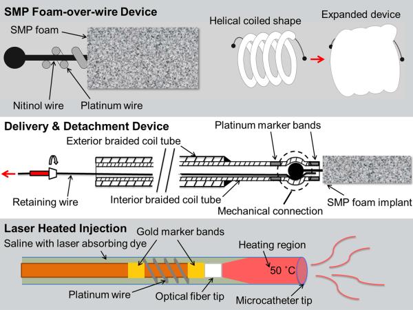
The embolization device system consisted of an SMP foam-over-wire (FOW) implant device and a cable tube delivery and detachment device with an optional laser heated saline injection for SMP foam expansion as shown in Figure 1.
Figure 1.
Schematic diagrams of the SMP foam-over-wire (top panel), the delivery and detachment device (middle panel), and the laser heating mechanism (bottom panel).
2.1.1. Shape Memory Polymer Foam-over-Wire Implant
The implant device consists of SMP foam secured around a platinum wound nitinol backbone wire (Figure 1, top panel). N,N,N′,N′-Tetrakis(2-hydroxypropyl)ethylenediamine (HPED, 99%), triethanolamine (TEA, 98%), trimethyl-1,6-hexamethylene diisocyanate, 2,2,4-and 2,4,4- mixture (TMHDI), and deionized (DI) water (> 17 MΩ cm purity) were used as received to synthesize SMP foams using protocol reported previously.19 Under sonication, 8 mm SMP foam cylinders were chemically etched in 0.1 M hydrochloric acid, cleaned using isopropyl alcohol and detergent, and then rinsed with reverse osmosis (RO) water. Cleaned foam cylinders were dried overnight in an oven at 50 °C under vacuum.
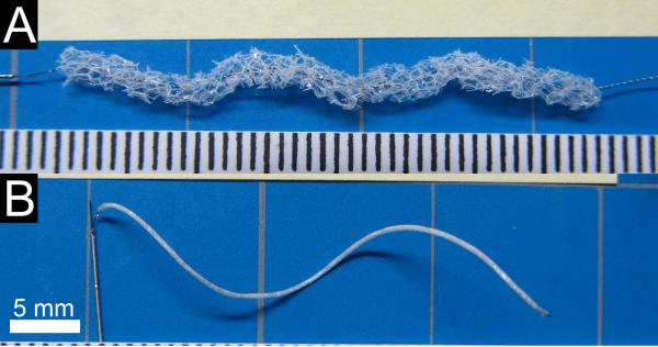
The platinum-nitinol wire backbone was annealed over a mandrel in a furnace to set a helical shape, quenched in water, and cleaned using isopropyl alcohol. SMP foam cylinders were cut from the cleaned and dried cylinders using a 2.5 mm diameter biopsy punch blade adhered to the end of a 2.97 mm ID stainless steel tube and the wire backbone was threaded axially through the SMP foam (Figure 2A). Devices were fabricated with both 2 cm and 4 cm total lengths of SMP foam. The implant devices were held taught and the SMP foam was radially compressed (Figure 2B) using a heated SC250 Stent Crimper†. Medical grade UV-cure epoxy was used to secure the compressed SMP foam at each end of the device.
Figure 2.
FOW embolization device. A) The threaded device prior to radial compression and attachment to the delivery and detachment device. Scale is mm. B) The assembled embolization device with compressed FOW device attached to the delivery and detachment device.
2.1.2. Delivery and Detachment Device
The braided coil assembly (Figure 1, middle panel) consisted of a 0.31 mm OD stainless steel ACTONE™ cable tube‡ reinforced with a 0.46 mm OD stainless steel ACTONE™ cable tube for distal flexibility and reinforced proximal pushability. A nitinol retention wire was passed through the entire length of the braided coil assembly. A laser welding system was used to secure a platinum marker band 4 mm from the distal tip of the braided coil assembly. A ball tip was created on each end of the implant using the laser welder and the ball tip was press-fit into the distal tip of the delivery system on top of the retaining wire, causing the braided coil to distend and apply a spring force on the ball tip. A second platinum marker band was laser welded at the distal tip of the delivery system to constrain the implant ball tip. The assembled devices were individually sealed in a sterilized pouch with desiccant and, for the in vivo studies, sterilized by ethylene oxide and allowed to degas for 24 hours.
2.1.3. Laser Heater Device and Injection
Fiber optic cables were fabricated using 200/220/239 μm core/cladding/buffer optical fiber and connectorized with 230 μm ST epoxy fiber connectors. Reinforced furcation and polytetrafluoroethylene tubing segments were placed over the proximal 30 cm of the fiber. Gold marker bands were epoxied to the optical fiber at the distal tip and 2 cm proximal to the distal tip using medical grade thermal cure epoxy. Two platinum wires were laser welded to opposite sides of the marker bands and wound around the fiber. The injected solution consisted of phosphate buffered saline doped with indocyanine green (ICG) at a concentration of 375 μM. The concentration was chosen to achieve a penetration depth of approximately 300 μm by interpolating data collected by Landsman et al.20 A full schematic of the laser heated injection is shown in the bottom panel of Figure 1.
2.2. In vitro Device Studies
2.2.1. SMP Foam Actuation
SMP foam actuation was characterized using simulated passive and active actuation methods. FOW devices were submerged in 37 °C RO water to simulate passive actuation and imaged at 2 min interval to 20 min and 5 min interval to 60 min total submersed time. To simulate active actuation, devices were submerged in 37 °C RO water for 5 min, then submerged in 50 °C RO water and imaged at 1 min interval to 15 min total submersed time. Imaging software was used to measure the foam diameter at 5 points along the length of each sample at each time point.
2.2.2. Aneurysm Model Fabrication and Flow System
An aneurysm model consisting of a 10 mm diameter sphere embedded in the side of a 5 mm diameter cylinder was designed in CAD software, printed using a fused deposition modeling system, and smoothed using sandpaper. Sylgard 184 polydimethylsiloxane (PDMS)§ was cast and cured around the model, and the printed model was dissolved using a heated base bath.
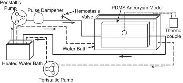
During testing, the PDMS aneurysm model was inserted in a flow loop as shown in Figure 3. Heated RO water was siphoned into a bath with the aneurysm model to maintain isothermal conditions at 37 °C. One peristaltic pump was used to maintain the water level above the submerged aneurysm model. A second peristaltic pump and pulse dampener supplied steady flow through the parent artery of the PDMS aneurysm model at approximately 240 mL/min to match the Reynold's Number of human common carotid artery peak blood flow rates reported by Holdsworth et al.21 A needle thermocouple was placed through a small port at the aneurysm dome to monitor temperature during setup and removed prior to device delivery.
Figure 3.
In vitro flow system schematic. The solid line indicates the simulated artery flow through the PDMS aneurysm model. The dashed line indicates the isothermal bath flow.
2.2.3. Embolization Device Delivery and Evaluation
Multiple FOW embolization devices were delivered via microcatheter into the aneurysm model. A 2.8/2.3 F proximal/distal microcatheter with a 0.53 mm lumen was navigated to the aneurysm using a guidewire. For each device, a hemostasis valve was used to secure a stainless steel hypotube introducer and the devices were advanced through the microcatheter to the aneurysm. Each device was positioned into the aneurysm such that the entire implant device was contained inside the aneurysm and the proximal platinum band at the distal tip of the delivery and detachment device was out of the microcatheter. The retaining wire on the delivery and detachment device was removed proximally and the cable tube was retracted into the microcatheter for complete release of the implant. The SMP foam passively actuated in the 37 °C water after implantation. Multiple devices were inserted into the aneurysm until the aneurysm was considered sufficiently occluded. Occlusion was indicated by qualitative visualization of extended dwell time or prevention of dye infiltrating the aneurysm. Theoretical volume occlusion (TVO) was calculated using Equation 1,
| Equation 1 |
where Vf is expanded foam volume, Va is the aneurysm volume, Df is the expanded foam diameter, Lf is the total foam length, and Da is the aneurysm diameter. The TVO calculation assumes the aneurysm is spherical and the SMP foam is a uniform cylinder of 1.25 mm diameter.
2.2.4. Laser Heater Characterization
Laser heater characterization was performed by recording the temperature of the aneurysm dome during heated injection in an in vitro flow loop similar the one shown in Figure 3. A microcatheter was passed through a hemostasis valve to the aneurysm dome. The optical fiber was inserted through a Y-adapter hemostasis valve and the tip was positioned approximately 2 cm proximal to the distal tip of the catheter. The ICG solution was injected using a syringe pump through the Y-adapter on the microcatheter. Systemic flow was discontinued and the ICG injection was initiated at a flow rate of 1.5 mL/min. An 808 nm continuous wave diode laser was activated to emit radiation at approximately 1.9–2 W. The temperature in the dome of the aneurysm was measured every ten seconds for two minutes. Three devices were used and three injections were characterized for each device.
2.3. In vivo Device Study
2.3.1. Porcine Sidewall Saccular Aneurysm Model Creation
Animal studies were conducted in accordance with policies set by the Texas A&M University Institutional Animal Care and Use Committee, and met all federal requirements as defined in the Animal Welfare Act, the Public Health Service Policy, and the Humane Care and Use of Laboratory Animals. Additionally, studies observed NIH guidelines (or for non-U.S. residents similar national regulations) for the care and use of laboratory animals (NIH Publication #85-23 Rev. 1985).
Animal studies were performed in the catheterization laboratory at the Texas A&M Institute for Preclinical Studies. Fluoroscopic visualization was achieved using the Allura Xper FD20 system**. A saccular sidewall vein pouch aneurysm model created in a 3-4 month old, 30–40 kg Yorkshire swine using a previously described model.22 Study subjects were premedicated with Telazol 5 mg/kg and 0.01 mg/kg buprenorphine administered intramuscularly. Following endotracheal intubation, study subjects were mechanically ventilated and maintained on isoflurane. Using sterile technique, a 10 cm incision was made in the ventral cervical midline and using a combination of sharp and blunt dissection the external jugular vein and carotid arteries were isolated. A 4 cm long segment of the external jugular vein was isolated, excised, and divided transversely to create two 2 cm open-ended pouches. The common carotid arteries were cleaned of adventitia, and vascular clamps placed at each end of the target area on the artery. A 3-4 mm arteriotomy was created and an end-to-side anastomosis of the venous pouch to the carotid artery performed using 7–0 polypropylene sutures. A 6–9 mm diameter aneurysm was created on each common carotid artery of two animals for a total of four aneurysms. After hemostasis was confirmed, the subcutaneous tissues were loosely closed.
2.3.2. Embolization Device Delivery and Angiographic Evaluation
Each aneurysm was accessed via endovascular technique for device delivery and implantation. A 6 F intravascular sheath was inserted percutaneously into the femoral artery with ultrasound guidance and a 5 F guide catheter was inserted through the introducer. Using fluoroscopic guidance, the guide catheter was advanced over a guidewire to the proximal right or** Koninklijke Philips N.V., Eindhoven, The Netherlands left carotid artery proximal to the aneurysm. Digital subtraction angiography with 3-D reconstruction angiography was performed to fully characterize each aneurysm. A 2.8/2.3 F proximal/distal microcatheter with 0.53 mm lumen was navigated to the aneurysm using a guidewire. Multiple FOW embolization devices were delivered through microcatheters and deployed in each aneurysm under fluoroscopic guidance. Devices were delivered and detached using the same methods used during in vitro studies. After implantation, the SMP foam passively expanded in the physiological conditions. Additional devices were inserted into the aneurysm until the aneurysm was considered sufficiently occluded. Implant time was measured per aneurysm as the time between entry of the first device into the microcatheter and detachment of the final device. Adequacy of occlusion was determined qualitatively by visualization of extended dwell time or prevention of dye infiltrating the aneurysm. TVO was calculated using Equation 1, where Da was the aneurysm diameter averaged from four measurements taken from angiographic images obtained using various angles, with the same assumptions as conducted for in vitro studies.
2.3.3. Laser Heated Injection
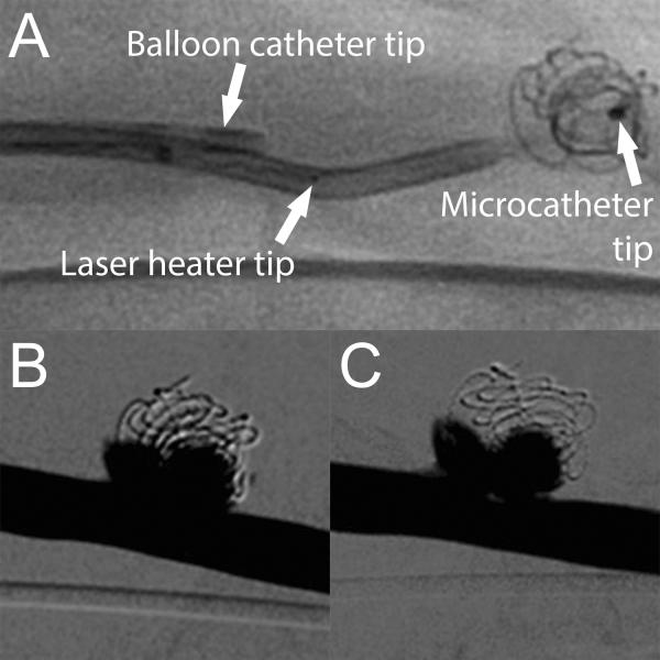
The laser heated injection was used in one aneurysm after implantation with FOW devices to accelerate and increase expansion of the SMP foam. The laser heating device was positioned using the same methods used during in vitro studies. A second 6 F introducer was inserted into the femoral artery on the opposite side of the previous introducer. A 5 F balloon catheter was inserted through the second introducer and positioned proximal to the aneurysm site adjacent to the guide catheter. The balloon catheter was inflated to prevent blood flow to the aneurysm and ICG-doped saline was injected at 1.5 mL/min through the microcatheter. The same laser used for in vitro studies was activated for 2 min during injection. After injection, the balloon catheter was deflated and angiography was performed to confirm aneurysm integrity and assess any change in aneurysm occlusion.
2.3.4. Ex vivo Evaluation
After implantation and angiographic imaging of both aneurysms in each animal, the animal was sacrificed and the aneurysms explanted and rinsed in saline. The parent artery was divided axially and the aneurysm neck was exposed and imaged. The aneurysm wall was opened and the implanted devices were imaged within the aneurysm sac and after removal from the aneurysm to evaluate implant device stability, aneurysm occlusion, and clotting.
3. Results
3.1. In vitro Device Studies
3.1.1. SMP Foam Actuation
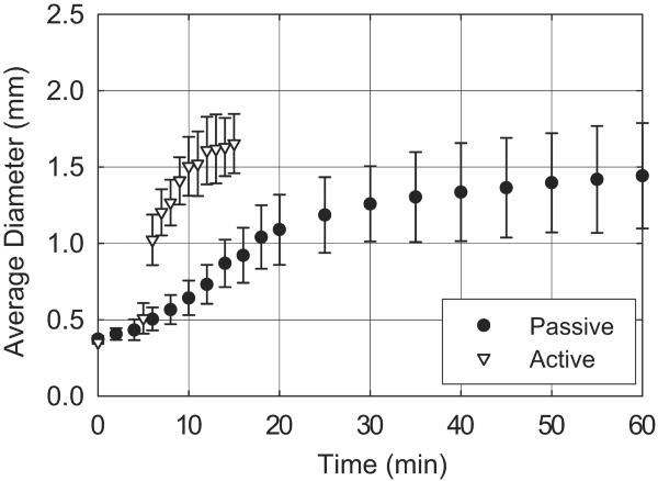
As shown in Figure 4, SMP foam submerged in 37 °C RO water actuated to an average diameter less than 0.53 mm after 5 min, 1.26 mm after 30 min, and 1.44 mm after 60 min. After 5 minutes of submersion in 37 °C RO water, SMP foam submerged in 50 °C RO water actuated to an average diameter of 1.02 mm within 1 min and 1.65 mm after 10. Three samples were tested per actuation method.
Figure 4.
SMP foam expansion using simulated passive and active actuation methods.
3.1.2. Embolization Device Delivery
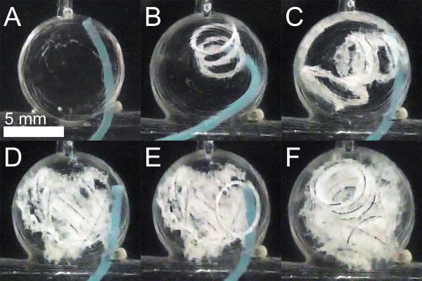
The spherical aneurysm model was fabricated with a dome diameter of 9.79 ± 0.12 mm and a neck diameter ranging 2.09–6.81 mm. Embolization device delivery into the aneurysm model is shown in Figure 5. Four FOW devices 4 cm in length were delivered to the aneurysm model. Two of four implant devices were detached without complication, whereas two devices detached in the microcatheter during repositioning and were successfully deployed using a guidewire. All four devices were implanted into the aneurysm model without migration into the parent vessel. TVO was calculated to be 40%.
Figure 5.
FOW device in vitro delivery. A) Aneurysm model prior to device delivery. B–E) Delivery of four devices into the aneurysm model. F) Aneurysm model is well occluded.
3.1.3. Laser Heater Characterization
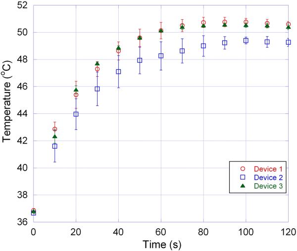
The conducted in vitro tests showed that three of the tested devices increased the aneurysm dome temperature to at least 49 °C after 1–1.5 minutes of injection.
3.2. In vivo Device Study
3.2.1. Embolization Device Delivery and Angiographic Evaluation
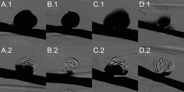
After aneurysm formation, three of four aneurysms exhibited good stability via angiography, while one aneurysm showed hemorrhage at the anastomosis site. All four aneurysms were successfully treated with FOW embolization devices with an average implant time of 65.0 ± 16.4 min. Figure 7 summarizes angiographic evaluation of each aneurysm before and after treatment. All treated aneurysms exhibited significant occlusion, particularly at the dome apex, with reduced contrast infiltration into the aneurysm. Hemorrhage at the anastomosis site shown in panel D.1 is no longer seen after treatment as shown in panel D.2. The minimal TVO calculated for the four aneurysms was 72% (Table 1).
Figure 7.
FOW device treatment of porcine sidewall aneurysms labeled A, B, C, and D. Top Row: Digital subtraction angiography prior to device implantation. Bottom Row: Digital subtraction angiography after implantation of FOW devices.
Table 1.
Aneurysm model and device dimensions and TVO values
| Aneurysm Label | Aneurysm Diameter (mm) | Neck Diameter (mm) | No. Devices | Total Device Length (cm) | Theoretical Volume Occlusion |
|---|---|---|---|---|---|
| A | 8.66 ± 1.45 | 4.42 | 6 | 20.0 | 72% |
| B | 7.45 ± 1.11 | 4.63 | 4 | 16.1 | 91% |
| C | 7.78 ± 1.91 | 4.42 | 6 | 14.9 | 74% |
| D | 5.74 ± 0.77 | 3.40 | 3 | 11.4 | 141% |
Embolization devices were delivered and implanted in the aneurysms with minimal complications. All device components were clearly identified under fluoroscopy. 19 of 26 (73%) FOW devices inserted into the microcatheter were successfully implanted in aneurysms, two devices could not be packed into aneurysms that had already occluded, and five devices could not be advanced due to excessive device expansion within the catheter. Delivery and detachment of devices was successfully performed in 24 of 26 (92%) attempts with both complications being detachment of the implant during repositioning. One detached device was delivered to the aneurysm using a guidewire and the other was partially packed in the aneurysm and subsequently removed using an endovascular snare system. As shown in Figure 8, the laser heated injection was conducted without complication and no acute adverse reactions were detected. Minimal reduction in contrast infiltration was observed following the laser heated injection.
Figure 8.
Laser heated injection for increased SMP foam expansion. A) Fluoroscopic image prior to balloon inflation and ICG-doped saline injection. Digital subtraction angiography of treated aneurysm prior to (B) and after (C) laser heated injection.
3.2.2. Ex vivo Evaluation
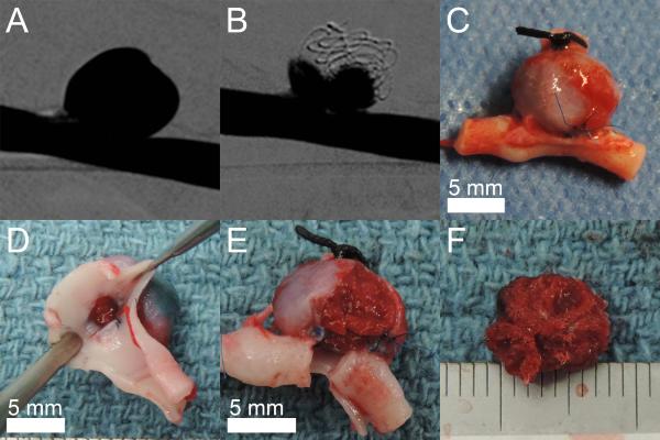
The explanted aneurysms showed no device perforation through the aneurysm wall and excellent thrombus formation throughout the implanted FOW devices. Figure 9 shows an explanted aneurysm and the aneurysm content of implanted devices and thrombus. All aneurysms were explanted within 3 hours after final device implantation in each aneurysm.
Figure 9.
Explanted porcine sidewall aneurysm model. A) Digital subtraction angiography of the aneurysm prior to treatment. B) Digital subtraction angiography of the aneurysm after implantation of four FOW devices. C) Explanted aneurysm including parent vessel. D) Visualization of the explanted aneurysm neck. E) Partial removal of the explanted aneurysm wall. F) Thrombus with the implanted devices is stable after removal from the aneurysm. Scale is mm.
4. Discussion
The primary goal of these studies was to evaluate the efficacy of FOW embolization devices for endovascular treatment of saccular aneurysms. The devices were tested using in vitro and in vivo saccular aneurysm models to measure and evaluate delivery and detachment efficacy, laser heating efficacy, aneurysm volume occlusion, and acute clotting.
Passive SMP foam actuation indicated a 5 min working time, during which time the foam is smaller than the delivery microcatheter ID (0.53 mm). This is equal to published repositioning times of the HydroCoils®.12 However, the foam diameters of 1.26 mm at 30 min passive actuation and 1.02 mm at 1 min active actuation are both greater than reported expanded diameter of HydroCoils® of 0.69 mm, indicating higher occlusion per device length of the FOW compared to HydroCoils®.12
The embolization device delivery in vitro demonstrated excellent positioning of multiple devices in the saccular aneurysm model with no device protrusion or migration into the parent vessel (Figure 5). The device detachment success rate of 50% revealed a need for increased grip strength and consistency in fabrication, both of which were implemented for devices fabricated for the in vivo study. Theoretical volume occlusion (TVO) of the in vitro study was lower than expected due to limited total device length of 16 cm relative to the large aneurysm diameter, but still resulted in greater than reported volume occlusion values for bare platinum coil treatments.3,4
All three laser heating devices increased the temperature (Figure 6) in the aneurysm dome during in vitro studies to a temperature 10 °C greater than the published SMP foam transition temperature for successful SMP foam actuation.19 Heating profile variation could be due to device imperfections or variation in the connector alignment and fiber tip location in the catheter.
Figure 6.
Heating profile of three different laser heating devices each tested three times.
Post treatment angiography during the in vivo study shown in Figure 7 exhibited complete elimination of flow into the aneurysm dome apex and substantial reduction of flow near the aneurysm neck in all 4 aneurysm models. FOW devices treated all porcine aneurysms with an average total device length of 15.6 cm, which is less than the average values reported when using bare platinum coils (52–53 cm) or HydroCoils® (31–38 cm) in similar sized aneurysms. Additionally, FOW device treatments resulted in TVO ranging 72–141%, which is equal to or greater than those reported by bare platinum coils (29–31%) or HydroCoils® (76–86%) in similar sized aneurysms.13–14 However, the aneurysm D value (Table 1) may be falsely high due to angiography measurements underestimating the actual diameter of the aneurysm possibly due to incomplete contrast filling due to the anastomosis hemorrhage of aneurysm D (Figure 7 D.1) before treatment. The porous structure and low radiographic contrast of the SMP foam enables contrast agent to infiltrate the foam and be visualized under fluoroscopy. Therefore, the absence of contrast agent flow into the aneurysm indicates complete thrombus formation within the implanted SMP foam. This is drastically different compared to treatments with bare platinum coils that saturate the aneurysm space with radiographic contrast, preventing visualization of any infiltrating contrast agent, and with HydroCoils® that displace blood from the aneurysm with hydrogel.13 In those cases, occlusion by thrombus formation cannot be reliably assessed in vivo. Thrombus formation within the porcine aneurysm models was confirmed by evaluation of the explanted aneurysms as shown in Figure 9. All aneurysm contents exhibited stable thrombus formation throughout the implant device mass. The formation of stable thrombus is an early and critical step in the inflammation response that has been shown to promote fibrous connective tissue formation within implanted SMP foams. The pore interconnectivity of the SMP foam enables connective tissue integration throughout the device volume within 30 days.18 This differs from occlusion with platinum coils that may not result in organized thrombus within 3 years or with HydroCoils® that show tissue deposition within 2–6 weeks around the devices, but little to no integration within the hydrogel due to the pore size.9,13 The thrombus formation throughout the explanted aneurysm mass also suggests that flow penetrating into two of the four treated aneurysms is an artifact of the 2D imaging overlaying flow around the outside of the ball of implanted contents.
Embolization devices were implanted with stable positioning of multiple devices in each saccular aneurysm model. Implant times for FOW devices were longer than reported average procedure times for platinum coils (27 min) and HydroCoils® (28 min) due to device complications.13 Implant devices had a moderate success rate with complications of increased delivery friction due to foam expansion in the microcatheter indicating a need for increased foam hydrophobicity to delay passive expansion.19 Detachment devices were able to deliver, reposition, and retract almost all devices without complication. The two detachment device complications were the direct result of either a fully packed aneurysm preventing device delivery or undesired SMP foam expansion and can be addressed without a detachment design change. The laser heating injection resulted in minimal decrease of contrast infiltration in the treated aneurysm, indicating either complete passive expansion of SMP foams or that the temperature increase was not sufficient to increase SMP foam expansion. However, no negative acute effects were observed as a result of the laser heating.
In conclusion, the FOW embolization device design combines the filling and surface area advantages of SMP foam with fluoroscopic contrast and mechanical stability of metal coils, providing a low adoption hurdle for clinicians experienced with coil devices. Furthermore, the in vitro and in vivo studies show great promise for the efficacy of the FOW embolization device for endovascular treatment of intracranial saccular aneurysms.
Acknowledgements
This work was supported by the A/National Institute of Biomedical Imaging and Bioengineering Grant R01EB000462. The authors thank Julie Grinde for her assistance with the in vivo studies.
Footnotes
Conflict of Interest: Shape Memory Therapeutics, Inc. (SMT) owns the commercial license for clinical vascular embolization application of the technology demonstrated in the manuscript. The authors disclose that Duncan Maitland is a founder, board member, shareholder, and the CTO of SMT. In addition, Todd Landsman, Landon Nash, and Wonjun Hwang are employed by SMT and, in addition to Anthony Boyle, hold stock options with SMT.
Microvention Inc., Tustin, CA
Machine Solution Inc.®, Flagstaff, AZ
Asahi Intecc Co., Aichi, Japan
Dow Corning Corp., Midland, MI
Koninklijke Philips N.V., Eindhoven, The Netherlands
References
- 1.Humphrey JD. Cardiovascular solid mechanics: cells, tissues, and organs. Springer; New York: 2002. p. 386. [Google Scholar]
- 2.Guglielmi G, Vinuela F, Sepetka I, Macellari V. Electrothrombosis of Saccular Aneurysms Via Endovascular Approach 1. Electrochemical Basis, Technique, and Experimental Results. J Neurosurg. 1991;75(1):1–7. doi: 10.3171/jns.1991.75.1.0001. [DOI] [PubMed] [Google Scholar]
- 3.Slob MJ, van Rooij WJ, Sluzewski M. Influence of coil thickness on packing, re-opening and retreatment of intracranial aneurysms: a comparative study between two types of coils. Neuro Research. 2005;27(Supplement-1):116–119. doi: 10.1179/016164105X49292. [DOI] [PubMed] [Google Scholar]
- 4.Wakhloo AK, Gounis MJ, Sandhu JS, Akkawi N, Schenck AE, Linfante I. Complex-shaped platinum coils for brain aneurysms: higher packing density, improved biomechanical stability, and midterm angiographic outcome. Amer J Neurorad. 2007;28(7):1395–1400. doi: 10.3174/ajnr.A0542. [DOI] [PMC free article] [PubMed] [Google Scholar]
- 5.Sluzewski M, van Rooij WJ, Slob MJ, Bescos JO, Slump CH, Wijnalda D. Relation between aneurysm volume, packing, and compaction in 124 cerebral aneurysms treated with coils. Radiology. 2004;231(3):653–658. doi: 10.1148/radiol.2313030460. [DOI] [PubMed] [Google Scholar]
- 6.Murayama Y, Nien YL, Duckwiler G, Gobin YP, Jahan R, Frazee J, Martin N, Vinuela F. Guglielmi detachable coil embolization of cerebral aneurysms: 11 years' experience. J Neurosurg. 2003;98(5):959–966. doi: 10.3171/jns.2003.98.5.0959. [DOI] [PubMed] [Google Scholar]
- 7.Raymond J, Guilbert F, Weill A, Georganos SA, Juravsky L, Lambert A, Lamoureux J, Chagnon M, Roy D. Long-term angiographic recurrences after selective endovascular treatment of aneurysms with detachable coils. Stroke. 2003;34(6):1398–1403. doi: 10.1161/01.STR.0000073841.88563.E9. [DOI] [PubMed] [Google Scholar]
- 8.Geyik S, Ertugrul O, Yavuz K, Geyik P, Saatci I, Cekirge HS. Comparison of bioactive coils and bare platinum coils for treatment of intracranial aneurysms: a matched-pair analysis. J Neurosurg. 2010;112(4):709–713. doi: 10.3171/2009.8.JNS081372. [DOI] [PubMed] [Google Scholar]
- 9.Szikora I, Seifert P, Hanzely Z, Kulcsar Z, Berentei Z, Marosfoi M, Czirjak S, Vajda J, Nyary I. Histopathologic evaluation of aneurysms treated with Guglielmi detachable coils or Matrix detachable microcoils. Amer J Neurorad. 2006;27(2):283–8. [PMC free article] [PubMed] [Google Scholar]
- 10.McDougall CG, Claiborne Johnson S, Gholkar A, Barnwell SL, Vazquez Suarez JC, Masso Romero J, Chaloupka JC, Bonafe A, Wakhloo AK, Tampieri D, Dowd CF, Fox AJ, Imm SJ, Carroll, Turk AS. the MAPS Investigators. Bioactive versus Bare Platinum Coils in the Treatment of Intracranial Aneurysms: The MAPS (Matrix and Platinum Science) Trial. Amer J Neurorad. 2014;35:935–942. doi: 10.3174/ajnr.A3857. [DOI] [PMC free article] [PubMed] [Google Scholar]
- 11.Cruise GM, Shum JC, Plenk H. Hydrogel-coated and platinum coils for intracranial aneurysm embolization compared in three experimental models using computerized angiographic and histologic morphometry. J Mater Chem. 2007;17:3965–3973. [Google Scholar]
- 12.Cloft HJ, Kallmes DF. Aneurysm packing with HydroCoil embolic system versus platinum coils: initial clinical experience. Amer J Neurorad. 2004;25(1):60–62. [PMC free article] [PubMed] [Google Scholar]
- 13.Ding YH, Dai D, Lewis DA, Cloft HJ, Kallmes DF. Angiographic and Histologic Analysis of Experimental Aneurysms Embolized with Platinum Coils, Matrix, and HydroCoil. Amer J Neurorad. 2005;26:1757–1763. [PMC free article] [PubMed] [Google Scholar]
- 14.Gaba RC, Ansari SA, Roy SS, Marden FA, Viana MA, Malisch TW. Embolization of intracranial aneurysms with hydrogel-coated coils versus inert platinum coils. Stroke. 2006;37:1443–1450. doi: 10.1161/01.STR.0000221314.55144.0b. [DOI] [PubMed] [Google Scholar]
- 15.White PM, Lewis SC, Gholkar A, Sellar RJ, Nahser H, Cognard C, Forrester L, Wardlaw JM. Hydrogel-coated coils versus bare platinum coils for the endovascular treatment of intracranial aneurysms (HELPS): a randomised controlled trial. Lancet. 2011;377(9778):1655–1662. doi: 10.1016/S0140-6736(11)60408-X. [DOI] [PubMed] [Google Scholar]
- 16.Lendlein A, Kelch S. Shape-memory polymers. Angewandte Chemie-International Edition. 2002;41(12):2034–2057. [PubMed] [Google Scholar]
- 17.Singhal P, Rodriguez JN, Small W, Eagleston S, Van de Water J, Maitland DJ, Wilson TS. Ultra low density and highly crosslinked biocompatible shape memory polyurethane foams. J Poly Sci B: Poly Phys. 2012;50(10):724–737. doi: 10.1002/polb.23056. [DOI] [PMC free article] [PubMed] [Google Scholar]
- 18.Rodriguez JN, Clubb FJ, Wilson TS, Miller MW, Fossum TW, Hartman J, Tuzun E, Singhal P, Maitland DJ. In vivo response to an implanted shape memory polyurethane foam in a porcine aneurysm model. J Biomed Mater Res A. 2014;102(5):1231–1242. doi: 10.1002/jbm.a.34782. [DOI] [PMC free article] [PubMed] [Google Scholar]
- 19.Singhal P, Boyle A, Brooks ML, Infanger S, Letts S, Small W, Maitland DJ, Wilson TS. Controlling the actuation rate of low-density shape-memory polymer foams in water. Macromol Chem and Phys. 2013;214(11):1204–1214. doi: 10.1002/macp.201200342. [DOI] [PMC free article] [PubMed] [Google Scholar]
- 20.Landsman MLJ, Kwant G, Mook GA, Zijlstra WG. Light-absorbing properties, stability, and spectral stabilization of indocyanine green. J Applied Physio. 1976;40(4):575–583. doi: 10.1152/jappl.1976.40.4.575. [DOI] [PubMed] [Google Scholar]
- 21.Holdsworth D, Norley C, Frayne R, Steinman D, Rutt B. Characterization of common carotid artery blood-flow waveforms in normal human subjects. Physio Measure. 1999;20(3):219–240. doi: 10.1088/0967-3334/20/3/301. [DOI] [PubMed] [Google Scholar]
- 22.Guglielmi G, Ji C, Massoud TF, Kurata A, Lownie SP, Viñuela F, Robert J. Experimental saccular aneurysms. Neurorad. 1994;36(7):547–550. doi: 10.1007/BF00593518. [DOI] [PubMed] [Google Scholar]


