Abstract
Purpose
To estimate k-space trajectory errors in non-Cartesian acquisitions and reconstruct distortion-free images, without trajectory measurements or gradient calibrations.
Theory and Methods
The Trajectory Auto-Corrected image Reconstruction (TrACR) method jointly estimates k-space trajectory errors and images, based on SENSE and SPIRiT parallel imaging reconstruction. The underlying idea is that parallel imaging and oversampling in the center of k-space provides data redundancy that can be exploited to simultaneously reconstruct images and correct trajectory errors. Trajectory errors are represented as weighted sums of trajectory-dependent error basis functions, the coefficients of which are estimated using gradient-based optimization.
Results
TrACR was applied to reconstruct images and errors in golden angle radial, center-out radial, and spiral in vivo 7 Tesla brain acquisitions in 5 subjects. Compared to reconstructions using nominal trajectories, TrACR reconstructions contained considerably less blurring and streaking, and were of similar quality to images reconstructed using measured k-space trajectories in the center-out radial and spiral cases. Reconstruction cost function reductions and improvements in normalized image gradient squared were also similar to those for images reconstructed using measured trajectories.
Conclusion
TrACR enables non-Cartesian image reconstructions free from trajectory errors with-out the need for separate gradient calibrations or trajectory measurements.
Keywords: image reconstruction, non-Cartesian imaging, parallel imaging, spiral, radial, center-out radial, golden angle radial, eddy currents
Introduction
Non-Cartesian k-space readout trajectories are used in several MRI applications, including functional brain imaging [1], cardiac imaging [2, 3], sodium imaging [4], and ultra-short echo time (UTE) imaging [5]. However, compared to Cartesian k-space readouts they are particularly sensitive to trajectory errors caused by gradient eddy currents, delays, and non-ideal gradient amplifier characteristics, which can result in severe image distortions. Modern scanners use gradient coil shielding and waveform pre-emphasis to prospectively avoid significant trajectory deviations in typical MR acquisitions. However, those methods are limited in terms of the magnitude and temporal dynamics of the errors for which they can compensate, and non-Cartesian trajectory gradient waveforms can easily push past those limits. Consequently, much research has focused on developing methods to compensate for non-Cartesian trajectory errors retrospectively.
One approach to retrospective trajectory error correction is to measure or predict the erroneous trajectory waveforms and use them in place of the nominal trajectory for image reconstruction. Mason et al. [6] proposed an early gradient waveform measurement technique using a point phantom to localize and measure the phase progression of a set of spins. To eliminate the need for precise placement of a physical phantom, Duyn et al. [7] and Zhang et al. [8] proposed measuring the phase accrual of spins due to a gradient waveform of interest by performing slice selection along the same axis as the encoding gradient. Gurney et al. [9] later introduced a modification to Duyn’s method to additionally allow the measurement of B0 eddy currents. Magnetic field monitoring is another measurement approach that uses susceptibility-matched NMR probes placed around the imaging volume in the scanner, and has the advantage of flexibility, in that it can be performed concurrently with any scan protocol [10]. The primary disadvantage of this approach is that it requires specialized hardware to be situated inside the already-crowded magnet bore. All gradient measurement approaches share the disadvantage that they cannot be performed retroactively as a post-processing step, for example after attempts at image reconstruction without corrections reveal the presence of artifacts in previously-acquired data. Predictive methods have also been proposed based on the calibration of a gradient system model; subsequently this model may be applied to predict errors for new input waveforms that might differ in terms of the orientation of the imaging plane [11] or the trajectory itself [12–14]. All of these techniques require calibration scans that can lengthen overall examination time. Some require only one-time or periodic calibration, but do not predict transient gradient errors such as those caused by variations in the gradient system response with gradient coil temperature increases. Predictive methods are also fundamentally limited by the models on which they are based. For example, linear time-invariant models cannot predict errors due to gradient amplifier nonlinearity, and most do not account for concomitant gradient terms due to the difficulty in measuring them.
Several recently-proposed methods for trajectory error correction do not require additional measurements, calibration scans or hardware [15–17], and focus on correcting errors in radial scans. These are iterative methods that estimate trajectory errors from the k-space data themselves, and work by exploiting a) data redundancy resulting from oversampling in the center of k-space, which is a universal characteristic of non-Cartesian trajectories in use today, and b) data redundancy provided by parallel imaging. They are members of a broader class of methods that aim to jointly estimate both images and other quantities such as receive sensitivity maps [18] and off-resonance maps [19] from k-space data. Deshmane et al. [15] proposed a method that iteratively shifts data in k-space with the goal of finding the set of shifts that produces the highest sum-of-squares (SOS) signal; the set of best shifts is then used to update the k-space trajectory used for reconstruction. Wech et al. [17] proposed a method that iteratively shifts radial projections in k-space, choosing the direction of those shifts based on the concordance of the resulting k-space data with the remainder of the dataset. These methods have the advantage that transient gradient errors can be captured retrospectively without the need for additional measurements. However, they are limited in their range of potential applications because the need to select specified shift directions and magnitudes would make for a large and potentially intractable combinatorial solution space when applying them to trajectories other than radial.
We propose a more general method to reconstruct images free of trajectory errors, called TRajectory Auto-Corrected image Reconstruction (TrACR), that is based on the same basic idea as the aforementioned measurement-free methods but uses a flexible gradient-based trajectory optimization approach. The method jointly estimates images and k-space errors, can be adapted to multiple trajectories, and can be used with multiple existing non-Cartesian parallel imaging reconstruction techniques. The method is evaluated with in vivo 7 Tesla brain data from radial, center-out radial, and spiral acquisitions in five human subjects. Performance of the method is investigated as a function of k-space acceleration factor and the number of receive coils. Center-out radial and spiral trajectory error estimates are validated against trajectory measurements. A preliminary account of this work was given in a 2014 ISMRM Annual Meeting abstract [20].
Theory
Problem Formulations
The TrACR method is formulated as a joint estimation of images and k-space trajectory errors, using extensions of the cost functions for SENSE [21, 22] and SPIRiT [23] non-Cartesian parallel imaging reconstruction to incorporate trajectory errors as additional variables. The cost function used for SENSE reconstruction is:
| (1) |
where f is a length-Ns vector of image samples to be reconstructed, Δk⃗ is a length-Nk vector of trajectory errors to be estimated, Nc is the number of receive coils, the dci are optional coil- and k-space location-dependent weights, yci is coil c’s ith k-space data sample, , k⃗i is the nominal ith k-space location, r⃗j is the jth spatial coordinate in the image, and scj is coil c’s receive sensitivity at r⃗j. In this work the dci are used to apply k-space density compensation to accelerate algorithm convergence. The cost function used for SPIRiT reconstruction is:
| (2) |
where f is now a length-NsNc vector of images for all coils, and is the SPIRiT regularization, where λ is a user-specified regularization parameter and S is the SPIRiT operator. Equation 2 is an extension of Eq. 10 in Ref. [23]. The individual coil images can be combined after SPIRiT reconstruction using any coil combination method [23]. In both the SENSE and SPIRiT cases we model the k-space trajectory errors Δk⃗i as a sum of weighted error basis functions:
| (3) |
where Nb is the number of error basis functions e⃗b. In order to minimize the required number of error basis functions, we construct them in a trajectory-dependent manner. Useful error basis construction approaches for radial, center-out radial, and spiral trajectories are described further in the Methods.
Algorithm
TrACR is an iterative method based on an alternating minimization approach, in which one of the parameters f or Δk⃗ is kept fixed while the other is updated. Accordingly, the algorithm comprises an outer loop which in each iteration invokes an f update, followed by a Δk⃗ update. For fixed Δk⃗, the cost functions in Eqs. 1 and 2 reduce to the original non-Cartesian SENSE and SPIRiT reconstruction problems and are typically minimized with respect to f using the Conjugate Gradient (CG) algorithm [24]. To update the k-space error weights w in Eq. 3 for fixed f, a nonlinear Polak-Ribière CG algorithm is used [24]. Each iteration of that algorithm requires the derivatives of the cost function with respect to w, in order to calculate the next search direction. Since by Eq. 3 each error weight wb affects all k-space trajectory dimensions, the total derivative for each weight will comprise a sum over the k-space dimensions. For the SENSE reconstruction problem, the contribution to the derivative of wb from the kx-dimension is:
| (4) |
where ℜ denotes the real part of the complex number in the braces, * indicates a complex conjugate, and rci is the residual:
| (5) |
Once the derivatives for each k-space dimension are computed, they are summed to obtain the total derivative for each weight, and the gradient vector of collected derivatives for all weights is returned to the CG algorithm. The derivatives of the SPIRiT cost function are obtained by replacing scjfj with fcj in Eqs. 4 and 5. The TrACR algorithm alternates between image and k-space error weight updates until a stopping criterion is met.
Methods
Algorithm Implementation
The TrACR algorithm was implemented in MATLAB 2014a (The Mathworks, Natick, MA, USA) on a desktop PC with an Intel Xeon E3-1240 3.4 GHz CPU (Intel Corporation, Santa Clara, CA, USA) and 16 GB of RAM. Image updates were initialized with zeros each outer iteration to avoid noise amplification. Except where otherwise noted, all images were reconstructed using MAT-LAB’s lsqr function, with a fixed tolerance of 10−2, both inside and outside the TrACR algorithm. This allowed the number of CG image iterations in each image update step to vary as needed; typically 2 to 10 iterations were used. All non-uniform discrete Fourier transforms were computed using a non-uniform fast Fourier transform (NUFFT) algorithm [25]. Density compensation weights (dci in Eqs. 1 and 2) were calculated using the method of Zwart et al. [26] using the nominal trajectories. For SPIRiT image reconstructions, the regularization parameter λ (Eq. 2) was fixed to 10% of the median of the absolute value of the k-space data. To enable direct comparison of SENSE and SPIRiT reconstructions, the SPIRiT kernel was calibrated using images obtained by applying the receive sensitivities measured for SENSE to a sum-of-squares Cartesian reconstruction. The CG algorithm for the k-space updates used a maximum of 5 iterations and a backtracking line search ([27], p. 464) with a maximum allowed trajectory change in one CG iteration of 1/FOV, where FOV is the reconstructed field-of-view. The outer loop of the TrACR algorithm was stopped when the k-space backtracking line search returned a zero step size in its first iteration. MATLAB code to implement the algorithm and a demonstration with an in vivo radial dataset are available at https://bitbucket.org/wgrissom/tracr/downloads.
Experiments
In vivo experiments were performed at 7 Tesla (Philips Achieva, Philips Healthcare, Best, Netherlands) using a quadrature volume coil for excitation and a 32-channel head coil (Nova Medical, Wilmington, MA, USA) for reception. Scans were performed in 5 healthy volunteers with approval from the Institutional Review Board of Vanderbilt University. Data were collected using 3 non-Cartesian trajectories: golden-angle (GA) radial, center-out radial, and multi-shot spiral, detailed further below. Cartesian scans were also collected and used to synthesize a body coil image and an estimate of the sum-of-squares receive sensitivity using a polynomial fit; the receive sensitivity was divided out of the reconstructed non-Cartesian images. Coil sensitivity measurements were collected for SENSE reconstructions. All scans were gradient echo sequences with repetition time and echo time matched for all trajectories, at 200 ms and 7.9 ms, respectively, and with 2.5 mm slice thickness. Center-out radial and spiral trajectory measurements for validation were collected in a spherical phantom for each scan session using a modified Duyn method [7, 9]. Trajectory measurements began 1 ms prior to the expected start of the gradient waveforms in order to capture components generated by the scanner’s gradient pre-emphasis.
The GA radial trajectory comprised 201 projections, each containing 256 sample points. Trajectory-specific acquisition parameters were: readout duration 0.46 ms, maximum gradient amplitude 16.1 mT/m and maximum gradient slew rate 7.9 T/m/s, water/fat shift 0.741 pixels. The center-out radial trajectory comprised 402 projections, each containing 170 sample points. Trajectory-specific acquisition parameters were: readout duration 0.34 ms, maximum gradient amplitude 25.5 mT/m, maximum gradient slew rate 114 T/m/s. The spiral trajectory comprised 16 shots of length 5.7 ms. Maximum gradient amplitude was 14.3 mT/m and the maximum gradient slew rate was 70 T/m/s. The trajectory was designed using Brian Hargreaves’ spiral design toolbox [28]. The resolution of each trajectory matched that of the 128 × 128 reconstruction grid. The reconstructed field of view was 25.6 cm and all trajectories were designed to sample k-space to a maximum frequency of ±2.5 cycles/cm. Where indicated, the data were coil-compressed prior to image reconstruction using singular value truncation [29].
Error Basis Generation
Golden-Angle Radial
Data sampling occurs only during the flat parts of the trapezoids in conventional and golden angle radial acquisitions, so the majority of trajectory errors can be captured by linear translations of the radial lines in k-space [15]. This leads to a straightforward trajectory error basis matrix construction E⃗ = (Ex Ey), as:
| (6) |
| (7) |
where INproj is an Nproj × Nproj identity matrix in which Nproj is the number of radial projections, ⊗ represents a Kronecker product, 1Nsamp×1 is a length-Nsamp vector of ones with Nsamp being the number of sample points per projection, and 0NprojNsamp×Nproj is a matrix of zeros.
Center-Out Radial and Spiral
In ramp-sampled center-out radial and spiral acquisitions, data are acquired while the gradients change amplitudes. The majority of trajectory errors are the result of eddy currents generated on conducting structures in the scanner which produce gradient field errors. These gradient field errors are typically modeled as a weighted linear combination of terms of the form ([30], p. 320):
| (8) |
where each term has a different value of the time constant τ, t is time, G(t) is the nominal gradient waveform, and H(t) is the Heaviside step function. For a given center-out radial or spiral readout gradient waveform G(t), this model was used to calculate error basis vectors by generating functions ge(t, τ) for 1000 time constants spaced linearly between 1 μs and 2 ms, and sampled with the same dwell time as the measured k-space data. The functions were integrated to arrive at a k-space error basis set, then compressed down to six linearly-independent waveforms by stacking them into a matrix Ge, calculating its singular value decomposition (SVD) Ge = USV′, and taking the first six columns of the matrix U (corresponding to the six largest singular values) as the error basis for that input gradient waveform. For the center-out radial case, the compressed error basis matrix was calculated for a single trapezoid and was rotated for each projection, forming the final error basis matrix E⃗ = (Ex, Ey) as:
| (9) |
| (10) |
where G̃ is the SVD-compressed error basis matrix. For the spiral case, compressed error basis matrices were calculated for the Gx(t) and Gy(t) waveforms for one of the 16 shots. These were then rotated to form the final error basis matrix E⃗ = (Ex, Ey) as:
| (11) |
| (12) |
In total, 6 error weights were fit in the center-out radial case and 12 in the spiral case. The definitions in Eqs. 9–12 are based on the empirical observation that the trajectory errors were very similar for the x and y gradient channels, so a single set of error coefficients can be estimated that applies to all shots/projections. For non-axial slice planes, it may be more accurate to estimate separate error coefficients for each gradient channel. Finally, on our scanner, the vendor’s gradient pre-emphasis on our scanner resulted in a temporal gradient delay that was found to be constant between scans, subjects, and trajectories; this shift was measured and applied to the nominal gradient waveforms provided to our algorithm. Alternatively, one could disable waveform pre-emphasis for such acquisitions.
Results
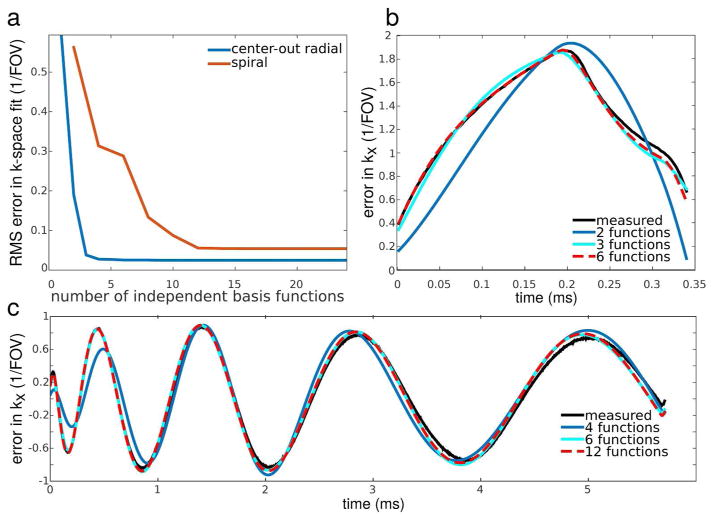
Figure 1 illustrates the accuracy with which the generated error basis functions can be fit to the measured trajectory errors in the center-out radial and spiral cases. This was investigated by directly fitting (by least-squares, without the TrACR algorithm) the error basis functions to the measured errors for the first projection/shot, while varying the size of the SVD-compressed error bases. Figure 1a plots the root-mean-square (RMS) error in fitting the measured trajectory errors, as a function of the number of basis functions used. For both trajectories, as the size of the SVD-compressed basis set increased, the error monotonically decreased to a minimum value and then flattened out. Figure 1b plots least-squares fits of 2, 3 and 6 basis functions to the error measured for the first projection of the center-out radial trajectory. For 6 basis functions, the measured and fit curves nearly coincide. Figure 1c plots least-squares fits of 4, 6 and 12 basis functions to the error measured for the first shot of the spiral trajectory (only the kx error waveform is shown). For 12 basis functions, the measured and fit curves nearly coincide. These results support the use of 6 basis functions for the center-out radial TrACR reconstructions that follow, and 12 basis functions for the spiral TrACR reconstructions.
Figure 1.
Investigation of the number of SVD-compressed error basis functions necessary to accurately model trajectory errors. (a) Residual error for direct least-squares fits of basis functions to the measured trajectory error for the center-out radial and spiral trajectories versus the number of independent basis functions used. (b) Direct least-squares fits of 2, 3, or 6 independent basis functions to the measured error for one projection of the center-out radial trajectory. (c) Direct least-squares fits of 4, 6, or 12 independent basis functions to the measured error for one shot of the spiral trajectory in the kx dimension.
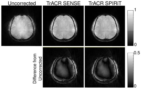
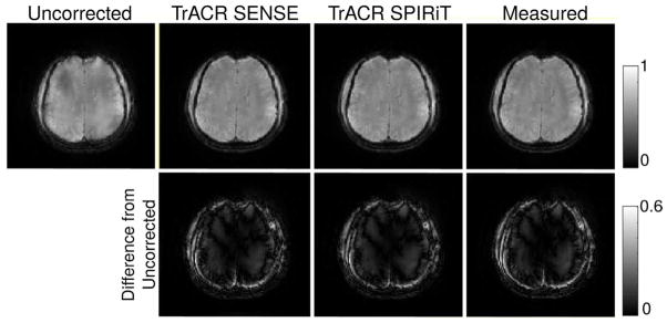
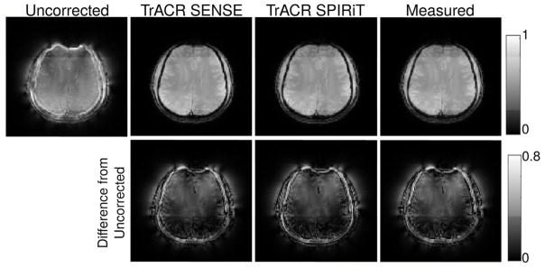
Figures 2–4 show golden angle radial, center-out radial, and spiral images reconstructed using the nominal trajectories, the measured trajectories (center-out radial and spiral only) and the trajectories estimated using TrACR with SENSE and SPIRiT, in the same subject and slice. For each case, the displayed image was formed as a sum-of-squares combination of the individual coil images reconstructed by CG using the final trajectory. Before running TrACR, the 32-channel coil data was compressed to 15 channels. In all cases, the uncorrected image contains considerable intensity modulations and blurring across the brain, which are removed in both SENSE and SPIRiT TrACR reconstructions. The difference images are similar in all cases, indicating that both TrACR-SENSE and -SPIRiT were effective in estimating the corrected trajectories, and (in the center-out radial and spiral cases) yielded similar image reconstructions as the measured trajectories. Across subjects, the mean number of TrACR iterations was: 27 (golden angle radial), 779 (center-out radial), and 205 (spiral). The mean compute time was: 8.7 minutes (golden angle radial), 2.7 hours (center-out radial), and 1.1 hours (spiral). The TrACR-SPIRiT reconstructions required between 10–40% more iterations/longer compute times.
Figure 2.
Final CG image reconstructions on nominal (uncorrected), TrACR-SENSE, and TrACR-SPIRiT trajectories for the golden angle radial dataset in one subject. The second row shows intensity differences between the TrACR reconstructions and the uncorrected image.
Figure 4.
Final CG image reconstructions on nominal, TrACR-SENSE, TrACR-SPIRiT, and measured k-space trajectories for the spiral dataset in one subject. The second row shows intensity differences between the corrected reconstructions and the uncorrected image.
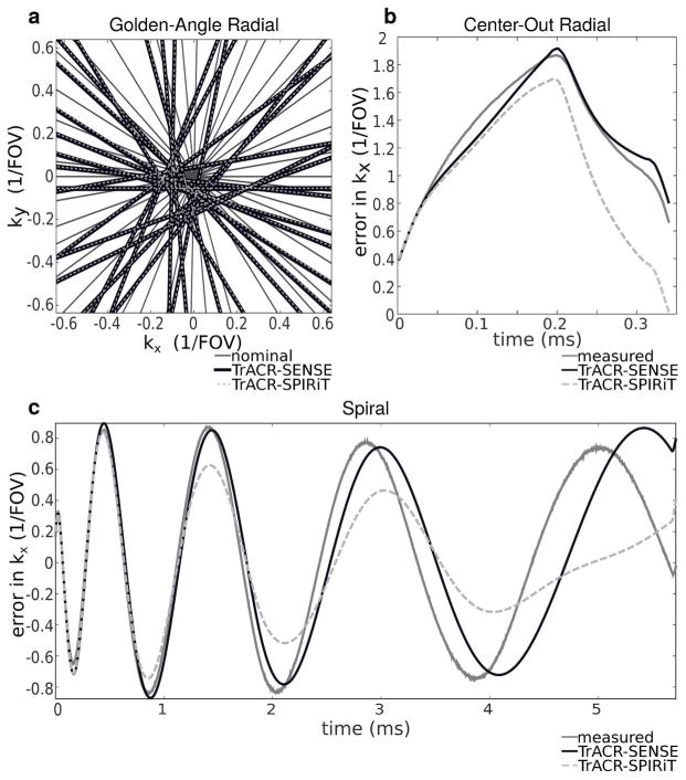
Figure 5 illustrates the estimated trajectories and errors for the subject shown in Figs. 2–4. Figure 5a shows the center of the nominal golden angle radial trajectory and the trajectories estimated by TrACR-SENSE and -SPIRiT. The TrACR-SENSE and -SPIRiT trajectories are indistinguishable on this plot, and differ considerably from the nominal trajectory. Figure 5b plots the measured and estimated k-space errors for a single projection of the center-out radial trajectory, as a function of time. While both trajectory estimates fit the measured error well at the beginning of the projection in the center of k-space, at higher spatial frequencies near the end of the projection the TrACR-SENSE estimate is closer to the measured error. The higher accuracy achieved at low spatial frequencies reflects the fact that the MR signal amplitude is much higher in the center of k-space, so the algorithm favors minimizing trajectory errors there. Figure 5c shows an analogous result for the spiral case: the error estimates are very close to the measured trajectory near the center of k-space, and diverge somewhat with increasing time/spatial frequency, and the TrACR-SENSE estimate comes closer to the measured trajectory than does TrACR-SPIRiT. Although the trajectories estimated by TrACR-SENSE and TrACR-SPIRiT differ in the high spatial frequencies in the center-out radial and spiral cases, those differences did not result in significant differences in the final reconstructed images in Figures 3 and 4.
Figure 5.
Trajectory errors for the image reconstructions in Figs 1–3. (a) A subset of nominal golden angle radial projections and their corresponding TrACR-SENSE and TrACR-SPIRiT projections in the center of k-space. The TrACR-SENSE and TrACR-SPIRiT projections coincide. (b) Measured, TrACR-SENSE and TrACR-SPIRiT center-out radial k-space trajectory error curves as a function of time, for one projection. (c) The same curves in (b) for the kx(t) waveform of one shot of the spiral trajectory. Trajectories and errors are plotted in units of multiples of 1/FOV.
Figure 3.
Final CG image reconstructions on nominal, TrACR-SENSE, TrACR-SPIRiT, and measured k-space trajectories for the center-out radial dataset in one subject. The second row shows intensity differences between the corrected reconstructions and the uncorrected image.
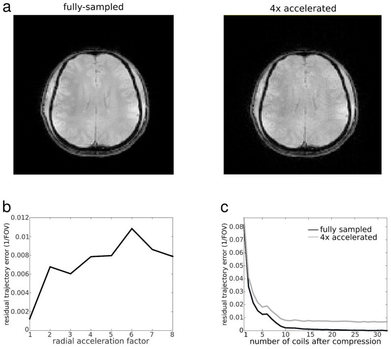
To investigate the dependence of the trajectory error on k-space acceleration and the number of receive channels, the golden angle radial TrACR-SENSE reconstructions in this subject were repeated for acceleration factors between 1 and 8, and for numbers of receive channels between 1 and 32. Acceleration was realized by uniformly dropping projections, and the number of channels was varied using SVD coil compression. Figure 6a shows fully-sampled and 4x-accelerated (50 projection) image reconstructions using CG-SENSE and the final TrACR trajectories (in this case images were reconstructed using lsqr with a stopping tolerance of 10−1). With 4× acceleration, there is an apparent loss of SNR but no noticeable aliasing artifacts. The same figure also plots the root-mean-square (RMS) trajectory error for each acceleration factor, referenced to the fully-sampled 32-channel TrACR-SENSE result. The errors were calculated after subtracting off the mean k-space trajectory shift, and were low for all acceleration factors, increasing only slightly with acceleration. Figure 6b plots the trajectory errors across numbers of receive channels, referenced to the fully-sampled 32-channel TrACR-SENSE result. As the number of coils used for reconstruction increased, the trajectory error decreased for both acceleration factors. For less than 10 coils, the error was higher with both full sampling and 4× acceleration than it was at any acceleration factor with 15 coils, indicating that in the golden angle radial case the trajectory error depends more on the number of coils than on the acceleration factor.
Figure 6.
Error vs. radial acceleration. (a) TrACR-SENSE corrected CG-SENSE reconstructions for full sampling and 4× acceleration. (b) RMS k-Space trajectory error versus radial acceleration factor for GA radial TrACR-SENSE reconstructions with 15 coils. (c) Error versus number of coils used for TrACR-SENSE, for full sampling and 4× acceleration. All errors are expressed as multiples of 1/FOV and are referenced to the fully-sampled 32-channel TrACR-SENSE trajectory estimate.
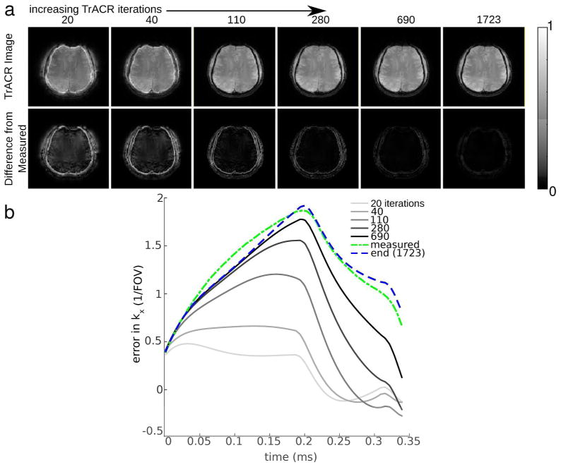
Figure 7 shows the evolution of the k-space error estimates and images over TrACR outer loop iterations, for center-out radial TrACR-SENSE. Images are shown on top, with center-out radial k-space estimates shown at the same TrACR iteration numbers on the bottom and the measured trajectory error provided for reference. The image improves rapidly with early TrACR iterations as the lower k-space locations are corrected, whereas high frequency corrections build up more slowly.
Figure 7.
Evolution of TrACR-SENSE images and trajectory error estimates versus TrACR outer loop iteration, for a center-out radial reconstruction. (a) Images and magnitude differences between the TrACR image and an image reconstructed using a measured k-space trajectory, versus number of TrACR iterations. (b) Corresponding k-space error estimates, plotted with the final TrACR trajectory error estimate and the measured trajectory error.
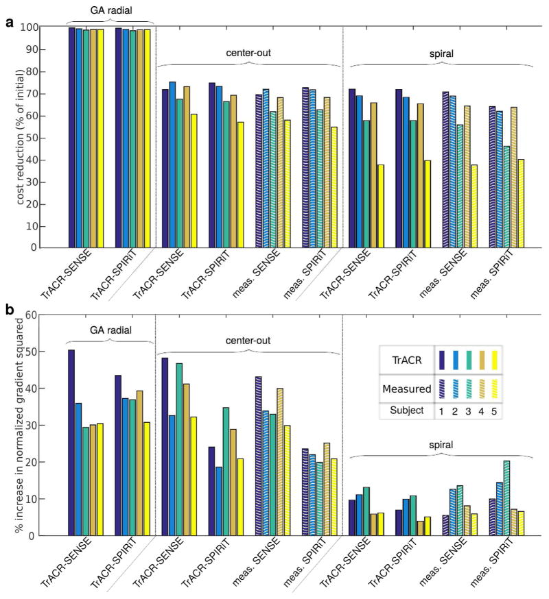
Figure 8 summarizes the performance of TrACR across the 5 subjects, 3 trajectories, and SENSE and SPIRiT formulations. Figure 8a shows how much lower (in percent; higher numbers are better) the final TrACR trajectories’ cost functions (Eqs. 1 and 2) were, compared to no correction. All instances of TrACR significantly reduced the uncorrected image cost, with a median cost reduction across subjects and trajectories of 76%. The same figure also shows the SENSE and SPIRiT cost reductions for the measured trajectories, which in all cases were not markedly higher than the TrACR cost reductions. Figure 8b shows the increase in normalized image gradient squared for each case, compared to the uncorrected images. The normalized image gradient squared is an image quality metric that has been reported as having a high correlation with observer image quality rating [31]. It was calculated from the final SENSE and SPIRiT image reconstructions. All reconstructions resulted in increased normalized image gradient squared, which were comparable to values for images reconstructed using the measured k-space trajectories.
Figure 8.
Numerical TrACR-SENSE and -SPIRiT results across 5 subjects and the three trajectories. (a) Cost function (Eqs. 1 and 2) reduction as a percentage of the uncorrected (initial) cost. (b) Percentage increase in the normalized image gradient squared, versus no correction. Metrics for reconstructions using measured trajectories are also shown for the center-out radial and spiral cases.
Lastly, Fig. S1 of the Supporting Information shows that the TrACR-SPIRiT reconstructions are relatively insensitive to the SPIRiT regularization parameter λ, at least over two orders of magnitude for each trajectory. Figure S2 of the Supporting Information shows that a measured off-resonance map can be incorporated into the signal model for TrACR reconstruction. This may be desirable in body imaging where the range of off-resonances can be larger than in the brain, which may result in blurring that confounds trajectory error estimation. The spiral trajectory had the longest readout duration, and incorporating the measured map resulted in marked signal recovery in the front of the brain, but did not significantly affect the trajectory error estimate.
Discussion
In vivo experiments demonstrated TrACR’s ability to correct image artifacts caused by k-space trajectory errors in non-Cartesian acquisitions. TrACR corrections made significant visible improvements (reduced streaking and blurring, and enhancement of fine details) to the reconstructed images in the in vivo experiments, with comparable image quality to images reconstructed using measured k-space trajectories. Golden angle radial reconstructions across acceleration factors demonstrated that TrACR-estimated trajectories were less accurate at higher radial acceleration factors; however, the errors remained relatively low across acceleration factors due to the large signal magnitude and oversampling at the center of k-space even with sub-Nyquist radial sampling. The golden angle radial reconstructions with varying numbers of coils demonstrated that the method benefits from parallel imaging due to the data redundancy it provides, since error increased as the number of coils decreased. The algorithm performed consistently across five subjects, in terms of the amount by which the SENSE and SPIRiT cost functions were reduced, and in terms of the increase in normalized image gradient squared.
TrACR reconstructions were able to correct most of the measured errors in the center-out radial and spiral trajectories, as shown in Fig. 5. Due to the higher signal and higher sampling density in the center of k-space, the algorithm preferentially corrected trajectory errors there, and converged with somewhat higher residual errors at the higher spatial frequencies. Though it was not observed in our reconstructions, it is possible that the TrACR-estimated trajectory will have higher error than the uncorrected trajectory at the high spatial frequencies. This potential problem could be mitigated by multiplying the error basis functions with a window that decreases to zero at the high frequencies. We have tested this approach with the spiral reconstructions (results not shown) and found that it performed similarly to the unwindowed reconstructions, with negligible image differences when the windows truncated the error functions at approximately 75% of the maximum k-space radius. Windowing the error basis may also accelerate algorithm convergence, since (as demonstrated in Fig. 7) the low frequencies are fitted early in the TrACR iterations.
The center-out radial and spiral results suggest that accurate corrections at high spatial frequencies may be precluded for cases in which there is a long separation in time between sampling the center of k-space and the end of the trajectory. The algorithm’s success also depends on the provision of a suitable error basis. In this work, error bases for spiral and center-out radial trajectories were derived from eddy current models, and this construction approach can be applied to any existing readout trajectory. However, error basis functions derived from eddy current models may not be effective in capturing other sources of error, such as errors due to gradient amplifier non-linearity and long-time constant eddy currents that persist between TRs. Developing suitable error bases in those cases may require the incorporation of hysteresis models (for amplifier non-linearity) and whole-sequence eddy current modeling (for long-time constant eddy currents). Furthermore, while an eddy current error basis can be constructed for any trajectory, properties of the trajectory itself may still preclude effective corrections. Specifically, we expect that TrACR would not be broadly effective in correcting errors in Cartesian readouts, since every line does not cross the center of k-space and the lines may not be spaced close enough together. However, with the exception of echo planar imaging, eddy currents are relatively benign in Cartesian readouts.
An important consideration in the TrACR-SPIRiT reconstruction is the choice of images used to calibrate the SPIRiT operator. We have found that in many cases the algorithm will converge to an acceptable solution if the operator is initially calibrated using low-resolution images reconstructed with the nominal trajectory, and is periodically re-calibrated during the TrACR iterations using the latest trajectory error estimate (results not shown). However, due to model inconsistencies inherent in that approach, it is possible for the iterations to diverge or converge to an unacceptable solution. Therefore a more cautious alternative is to calibrate the operator using Cartesian images of the same geometry, as described in [23]. This is the approach that was used here. Another consideration that may affect both TrACR-SENSE and -SPIRiT performance is the density compensation. In this work, density compensation weights for all TrACR reconstructions were calculated using the nominal trajectory, and were held fixed over the iterations. The weights were then updated using the TrACR error estimate for the final image reconstruction. Slightly better trajectory estimates may be possible by either periodically updating the density compensation, or by not using density compensation at all, which would require increasing the number of iterations used in each image update.
The computation times for the algorithm were shortest for golden-angle radial, and longest for center-out radial. This result was expected since the golden-angle radial trajectory error basis functions were uniform across each projection, so determining their weights could likely be performed using only the center of k-space, and it was found that the algorithm preferentially corrected trajectory errors there first. The large difference between the computation times for the spiral and center-out radial trajectories is likely due to the fact that the initial center-out radial RMS trajectory errors neared 1/FOV, or the Nyquist sample spacing, whereas the spiral and golden angle radial trajectory errors were about half as large. Overall, the reported computation times of several minutes (golden angle radial) to a few hours (center-out radial) were not compatible with online use. However, in the current implementation the TrACR algorithm was stopped when the backtracking line search returned a zero step size in the first iteration. The motivation for this stopping criterion was to demonstrate the very best possible trajectory correction with the algorithm. In practice we have found that the reconstructed images stop changing significantly well before this stopping criterion is satisfied, and that a more practical criterion that is predictive of this may be to stop the algorithm when the difference between consecutive cost function values falls below 0.1% of the current cost. Using this criterion resulted in approximately 75% shorter computation times/fewer iterations, with worse trajectory errors at high spatial frequencies compared to measurements in the center-out radial and spiral cases, but with negligible final image differences (results not shown). The algorithm’s computations could be accelerated using parallel computing [32, 33], and its convergence may be accelerated by jointly (rather than alternately) updating the images and trajectory errors each iteration. The alternating update approach used here was chosen primarily for its flexibility in decoupling the k-space error and image update codes. While CG is widely accepted as an efficient method for MR image reconstruction, algorithms other than CG may work better for the k-space error updates, such as Newton or Gauss-Newton methods. These could accelerate convergence at the cost of increased computational cost per iteration compared to CG.
Conclusions
The TrACR approach to auto-correct non-Cartesian images for k-space trajectory errors was described and validated in vivo for three non-Cartesian trajectories. It is a more general formulation than existing methods, and can be extended to any non-Cartesian trajectory for which a suitable trajectory error basis can be derived. It does not require trajectory measurements or prior calibration data and exploits data redundancy provided by oversampling in non-Cartesian acquisitions and parallel imaging. The method can be used in conjunction with multiple parallel imaging reconstruction techniques.
Supplementary Material
Figure S1: TrACR performance with varying SPIRiT regularization. (a) (Left) Spiral image re-construction before TrACR with the regularization set to λ0 (the same value used in the rest of this work), and (Right) spiral image reconstructed with TrACR with λ = λ0 × 10−2, λ = λ0, and λ = λ0 × 102. Images and errors are on the same color scale. (b) The data fidelity term of the cost function in Eq. 2 as a fraction of initial, versus SPIRiT regularization parameter for all 3 trajectories.
Figure S2: TrACR with off-resonance compensation. (a) The magnitude of the measured off-resonance map in Hz for one subject. The map is masked for display. The approximate 150 Hz offset in the front and right side of the brain would result in an approximately 1 cycle of phase across the spiral readouts. (b) Measured spiral trajectory error (solid blue), TrACR-estimated error with off-resonance incorporated (red dot-dashed), and TrACR-estimated error without off-resonance incorporated (yellow dashed). (c) Final reconstructed spiral images: (left) image reconstructed with the measured off-resonance map incorporated both in the TrACR and the final reconstruction, (center) image reconstructed with the off-resonance map incorporated in the final image reconstruction system matrix but not in the TrACR estimation, and (right) image reconstructed without off-resonance compensation in TrACR or the final reconstruction. Magnitude differences are also shown from the left reconstruction, on the same color scale. Off-resonance was incorporated in the reconstruction system matrices using time-segmentation [34].
Acknowledgments
This work was supported by NIH grants R25 CA136440 and R01 EB016695.
References
- 1.Noll DC, Cohen JD, Meyer CH, Schneider W. Spiral k-space MR imaging of cortical activation. J Magn Reson Imag. 1995;5:49–56. doi: 10.1002/jmri.1880050112. [DOI] [PubMed] [Google Scholar]
- 2.Nayak KS, Cunningham CH, Santos JM, Pauly JM. Real-time cardiac MRI at 3 Tesla. Magn Reson Med. 2004;51:655–660. doi: 10.1002/mrm.20053. [DOI] [PubMed] [Google Scholar]
- 3.Barger AV, Block WF, Toropov Y, Grist TM, Mistretta CA. Time-resolved contrast-enhanced imaging with isotropic resolution and broad coverage using an undersampled 3D projection trajectory. Magn Reson Med. 2002;48:297–305. doi: 10.1002/mrm.10212. [DOI] [PubMed] [Google Scholar]
- 4.Boada FE, Gillen JS, Shen GX, Chang SY, Thulborn KR. Fast three dimensional sodium imaging. Magn Reson Med. 1997;37:706–715. doi: 10.1002/mrm.1910370512. [DOI] [PubMed] [Google Scholar]
- 5.Tyler DJ, Robson MD, Henkelman RM, Young IR, Bydder GM. Magnetic resonance imaging with ultrashort TE (UTE) PULSE sequences: Technical considerations. J Magn Reson Imag. 2007;25:279–89. doi: 10.1002/jmri.20851. [DOI] [PubMed] [Google Scholar]
- 6.Mason GF, Harshbarger T, Hetherington HP, Zhang Y, Pohost GM, Twieg DB. A method to measure arbitrary k-space trajectories for rapid MR imaging. Magn Reson Med. 1997;38:492–6. doi: 10.1002/mrm.1910380318. [DOI] [PubMed] [Google Scholar]
- 7.Duyn JH, Yang Y, Frank Ja, van der Veen JW. Simple correction method for k-space trajectory deviations in MRI. J Magn Reson. 1998;132:150–3. doi: 10.1006/jmre.1998.1396. [DOI] [PubMed] [Google Scholar]
- 8.Zhang Y, Hetherington HP, Stokely EM, Mason GF, Twieg DB. A novel k-space trajectory measurement technique. Magn Reson Med. 1998;39:999–1004. doi: 10.1002/mrm.1910390618. [DOI] [PubMed] [Google Scholar]
- 9.Gurney P, Pauly JM, Nishimura DG. A Simple Method for Measuring B0 Eddy Currents. Proceedings of the 13th Annual Meeting of ISMRM; Miami Beach, Florida, USA. 2005; p. 866. [Google Scholar]
- 10.Barmet N, De Zanche Cand, Pruessmann KP. Spatiotemporal magnetic field monitoring for MR. Magn Reson Med. 2008;60:187–97. doi: 10.1002/mrm.21603. [DOI] [PubMed] [Google Scholar]
- 11.Tan H, Meyer CH. Estimation of k-space trajectories in spiral MRI. Magn Reson Med. 2009;61:1396–404. doi: 10.1002/mrm.21813. [DOI] [PMC free article] [PubMed] [Google Scholar]
- 12.Takizawa M, Hanada H, Oka K, Takahashi T, Yamamoto E, Fujii M. A robust ultrashort TE (UTE) imaging method with corrected k-space trajectory by using parametric multiple function model of gradient waveform. IEEE Trans Med Imag. 2013;32:306–16. doi: 10.1109/TMI.2012.2226050. [DOI] [PubMed] [Google Scholar]
- 13.Atkinson IC, Lu A, Thulborn KR. Characterization and correction of system delays and eddy currents for MR imaging with ultrashort echo-time and time-varying gradients. Magn Reson Med. 2009;62:532–7. doi: 10.1002/mrm.22016. [DOI] [PubMed] [Google Scholar]
- 14.Addy NO, Wu HH, Nishimura DG. Simple method for MR gradient system characterization and k-space trajectory estimation. Magn Reson Med. 2012;68:120–9. doi: 10.1002/mrm.23217. [DOI] [PMC free article] [PubMed] [Google Scholar]
- 15.Deshmane A, Blaimer M, Breuer F, Jakob PM, Duerk JL, Seiberlich N, Griswold MA. Self-calibrated trajectory estimation and signal correction method for robust radial imaging using GRAPPA operator gridding. Magn Reson Med. 2015 doi: 10.1002/mrm.25648. [DOI] [PMC free article] [PubMed] [Google Scholar]
- 16.Smith D, Welch B. Self-calibrated gradient delay correction for golden angle radial MRI. Proceedings of the 22nd Annual Meeting of ISMRM; Milan, Italy. 2014; p. 229. [Google Scholar]
- 17.Wech T, Tran-Gia J, Bley TA, Köstler H. Using self-consistency for an iterative trajectory adjustment (SCITA) Magn Reson Med. 2014 doi: 10.1002/mrm.25244. [DOI] [PubMed] [Google Scholar]
- 18.Ying L, Sheng J. Joint image reconstruction and sensitivity estimation in SENSE (JSENSE) Magn Reson Med. 2007;57:1196–1202. doi: 10.1002/mrm.21245. [DOI] [PubMed] [Google Scholar]
- 19.Sutton BP, Noll DC, Fessler JA. Dynamic field map estimation using a spiral-in/spiral-out acquisition. Magn Reson Med. 2004;51:1194–1204. doi: 10.1002/mrm.20079. [DOI] [PubMed] [Google Scholar]
- 20.Ianni JD, Grissom WA. k-SPIRiT: Non-Cartesian SPIRiT Image Reconstruction with Automatic Trajectory Error Compensation. Proceedings of the 22nd Annual Meeting of ISMRM; Milan, Italy. 2014; p. 83. [Google Scholar]
- 21.Pruessmann KP, Weiger M, Börnert P, Boesiger P. Advances in sensitivity encoding with arbitrary k-space trajectories. Magn Reson Med. 2001;46:638–651. doi: 10.1002/mrm.1241. [DOI] [PubMed] [Google Scholar]
- 22.Pruessmann KP, Weiger M, Scheidegger MB, Boesiger P. SENSE: Sensitivity encoding for fast MRI. Magn Reson Med. 1999;42:952–962. [PubMed] [Google Scholar]
- 23.Lustig M, Pauly JM. SPIRiT: Iterative self-consistent parallel imaging reconstruction from arbitrary k-space. Magn Reson Med. 2010;64:457–71. doi: 10.1002/mrm.22428. [DOI] [PMC free article] [PubMed] [Google Scholar]
- 24.Press WH, Teukolsky SA, Vetterling WT, Flannery BP. Numerical recipes: The art of scientific computing. Cambridge University Press; 1993. p. 1235. [Google Scholar]
- 25.Greengard L, Lee JY. Accelerating the nonuniform fast Fourier transform. SIAM Review. 2004;46:443–454. [Google Scholar]
- 26.Zwart NR, Johnson KO, Pipe JG. Efficient sample density estimation by combining gridding and an optimized kernel. Magn Reson Med. 2012;67:701–10. doi: 10.1002/mrm.23041. [DOI] [PubMed] [Google Scholar]
- 27.Boyd S, Vandenberghe L. Convex optimization. Cambridge University Press; 2004. p. 727. [Google Scholar]
- 28.Hargreaves B. [Accessed April 6, 2015];Variable-density spiral design functions. http://mrsrl.stanford.edu/~brian/vdspiral/
- 29.Huang F, Vijayakumar S, Li Y, Hertel S, Duensing GR. A software channel compression technique for faster reconstruction with many channels. Magnetic Resonance Imaging. 2008;26:133–141. doi: 10.1016/j.mri.2007.04.010. [DOI] [PubMed] [Google Scholar]
- 30.Bernstein MA, King KF, Zhou XJ. Handbook of MRI pulse sequences. Elsevier Academic Press; 2004. p. 1017. [Google Scholar]
- 31.McGee KP, Manduca A, Felmlee JP, Riederer SJ, Ehman RL. Image metric-based correction (autocorrection) of motion effects: Analysis of image metrics. J Magn Reson Imag. 2000;11:174–81. doi: 10.1002/(sici)1522-2586(200002)11:2<174::aid-jmri15>3.0.co;2-3. [DOI] [PubMed] [Google Scholar]
- 32.Murphy M, Alley M, Demmel J, Keutzer K, Vasanawala S, Lustig M. Fast ℓ1-SPIRiT compressed sensing parallel imaging MRI: Scalable parallel implementation and clinically feasible runtime. IEEE Trans Med Imag. 2012;31:1250–1262. doi: 10.1109/TMI.2012.2188039. [DOI] [PMC free article] [PubMed] [Google Scholar]
- 33.Wu XL, Gai J, Lam F, Fu M, Haldar JP, Zhuo Y, Liang ZP, Hwu WM, Sutton BP. IMPATIENT MRI: Illinois massively parallel acceleration toolkit for image reconstruction with enhanced throughput in MRI. Proceedings of the 19th Annual Meeting of ISMRM; Montreal, Quebec, Canada. 2011; p. 4396. [Google Scholar]
- 34.Fessler JA, Lee S, Olafsson VT, Shi HR, Noll DC. Toeplitz-based iterative image reconstruction for MRI with correction for magnetic field inhomogeneity. IEEE Trans Sig Proc. 2005;53:3393–3402. [Google Scholar]
Associated Data
This section collects any data citations, data availability statements, or supplementary materials included in this article.
Supplementary Materials
Figure S1: TrACR performance with varying SPIRiT regularization. (a) (Left) Spiral image re-construction before TrACR with the regularization set to λ0 (the same value used in the rest of this work), and (Right) spiral image reconstructed with TrACR with λ = λ0 × 10−2, λ = λ0, and λ = λ0 × 102. Images and errors are on the same color scale. (b) The data fidelity term of the cost function in Eq. 2 as a fraction of initial, versus SPIRiT regularization parameter for all 3 trajectories.
Figure S2: TrACR with off-resonance compensation. (a) The magnitude of the measured off-resonance map in Hz for one subject. The map is masked for display. The approximate 150 Hz offset in the front and right side of the brain would result in an approximately 1 cycle of phase across the spiral readouts. (b) Measured spiral trajectory error (solid blue), TrACR-estimated error with off-resonance incorporated (red dot-dashed), and TrACR-estimated error without off-resonance incorporated (yellow dashed). (c) Final reconstructed spiral images: (left) image reconstructed with the measured off-resonance map incorporated both in the TrACR and the final reconstruction, (center) image reconstructed with the off-resonance map incorporated in the final image reconstruction system matrix but not in the TrACR estimation, and (right) image reconstructed without off-resonance compensation in TrACR or the final reconstruction. Magnitude differences are also shown from the left reconstruction, on the same color scale. Off-resonance was incorporated in the reconstruction system matrices using time-segmentation [34].


