Abstract
Magnetic resonance angiography (MRA) is an extremely useful preoperative imaging test for evaluation of the vasculature of donor tissue to be used in autologous breast reconstruction. MRA has sufficient spacial resolution to reliably visualize 1 mm perforating vessels and to accurately locate vessels in reference to a patient’s anatomic landmarks without exposing patients to ionizing radiation or iodinated contrast. The use of a blood pool contrast agent and the lack of radiation exposure allow multiple studies of multiple anatomic regions in one examination. The following article is a detailed description of our MRA protocol developed with our radiologists with examples that illustrate the utility of MRA in perforator flap breast reconstruction.
Keywords: Perforator flap breast reconstruction, magnetic resonance angiography (MRA), imaging, deep inferior epigastric perforators (DIEP), superficial inferior epigastric artery (SIEA), deep circumflex iliac perforator flap (DCIP), profunda artery perforator (PAP), gluteal artery perforator (GAP), lumbar artery perforator (LAP), thoracodorsal artery perforator (TDAP), septocutaneous tensor fasciae latae (scTFL)
Introduction
Preoperative anatomic imaging of vasculature markedly enhances the ability of a surgeon to devise a surgical strategy before going to the operating room. Prior to the era of preoperative perforator imaging, a surgeon had little knowledge of an individual patient’s vascular anatomy until surgery was well underway. As a result, perforator selection could be a tedious and stressful decision process that occurred in the operating room at the expense of operating time and general anesthetic requirement.
Doppler
As technology has advanced, surgeons explored various modalities for preoperative imaging. Initially, a handheld Doppler ultrasound was solely used to attempt to locate perforating vessels. A Doppler ultrasound is portable and simple to use but cannot differentiate perforating vessels from superficial and deep axial vessels, large perforators from small ones. It cannot accurately determine the location that perforators exit the fascia, or provide information on the anatomic course of a vessel (1,2). In comparison, color Duplex sonography provides more detailed information about the anatomy of the vessels, but requires highly trained technicians with knowledge of perforator anatomy and is time-consuming (2). The technique’s most crucial drawback is an inability to produce anatomic images in a format that a surgeon can easily and independently view.
Computed tomographic angiography (CTA)
CTA is a modality that can demonstrate vessel anatomy, assess vessel caliber, accurately locate perforators, and produce anatomic images in a format that a surgeon can easily and independently view. Although CTA can be performed quickly in as little as 15 min (1,2), it requires that patients must be exposed to ionizing radiation. Radiation exposure precludes multiple repeated imaging studies in one examination. CTA may expose patients to excessive and potentially unnecessary radiation (3-6). Patients with breast cancer may have a heightened concern for any factor that can potentially increase the risk of developing a second cancer and may perceive the risks of radiation exposure even more negatively. Patients with breast cancer gene (BRCA) mutations, which confer an increased risk of developing both breast and ovarian cancer, are especially concerned about receiving radiation to the abdomen. Also, iodinated contrast to enhance vessels for CTA can be associated with small, but real risks of anaphylaxis and nephrotoxicity (7,8).
Magnetic resonance angiography (MRA)
Magnetic resonance imaging (MRI) uses a magnetic field to uniformly align the spin of hydrogen atoms in tissue. The subsequent application of a radiofrequency pulse results in release of energy as hydrogen atoms return to their relaxed state. MRI coils detect the released energy, and computer software processes the data into anatomic images. Exposure to a magnetic field or radiofrequency pulse with MRI has not been linked to the development of cancer (9). A paramagnetic contrast agent (gadolinium-containing) is injected to enhance vessels. Our previous papers demonstrated that MRA accurately locates perforating vessel branches and shows vessel anatomy in a format that is easily viewed by a surgeon (10-13). However, because MRI does not use radiation, this modality has an important advantage over CTA of allowing multiple series of images to be obtained.
Disadvantages of MRA are contraindication to use with a cardiac pacemaker or very claustrophobic patients. Most patients with claustrophobia can tolerate a MRI with an anxiolytic. Continuing advances in MRA have decreased the procedure time for a single donor site to as little as 20 min, and decreased the actual acquisition scan time to 20 s (11,13-15). However, the examination time could be 40 min for multiple donor site studies.
MRA contrast agents
Gadolinium-containing contrast agents used for MRA have several distinct advantages over iodinated contrast agents used for CTA. The incidence of an acute allergic reaction to iodinated contrast is 3%, which is much higher than the 0.07% incidence of allergic reaction to gadolinium contrast (7,16). Unlike gadolinium contrast agents, iodinated CT contrast agents can induce renal insufficiency even in patients with normal renal function (8,17). Gadolinium contrast agents can potentially induce nephrogenic systemic fibrosis (NSF), also called nephrogenic fibrosing dermopathy. However, reports of NSF have been limited to patients with impaired renal function (18-20). Patients with an acute kidney injury or chronic severe renal disease (glomerular filtration rate <30 mL/min/1.73 m2) are considered most at risk (18). NSF is a very rare disease with about 380 cases reported worldwide (19,20). Although, patients undergoing elective microsurgical free flap are generally healthy and thus are not at significant risk for developing NSF, a creatinine level is drawn preoperatively in patients with a history of hypertension, diabetes, renal disease or any other indication that renal function may be impaired.
Advances in gadolinium contrast agents with blood pool contrast agents have resulted in a decreased amount of contrast required, improved MR images, and increased even further the number of donor sites that can be imaged in one study. The MRA protocol developed with our radiologists uses 10 mL of gadofosveset trisodium, a blood pool MRI contrast agent. Prior to using this blood pool agent, 20 mL (instead of 10 mL) of gadolinium contrast (gadobenate dimeglumine) was required. Gadofosveset trisodium is a gadolinium chelate that reversibly binds to serum albumin with ~90% binding fraction, and effectively stays within the blood pool with a redistribution half-life of 28 min (21). It also demonstrates greater T1 relaxivity that allows administration of a 4-fold lower molecular dose while still conferring greater vascular enhancement compared to most other gadolinium chelates. This virtually eliminates the risk of NSF (22).
Gadofosveset improves vessel-to-muscle contrast ratio and vessel sharpness, mainly due to preferential enhancement of vessels compared to muscle derived from blood pool distribution of gadofosveset (23). This results in significantly improved images of the intramuscular course of perforating vessels, which gives valuable information for choosing the best perforating vessel and planning the intramuscular dissection.
Because blood pool contrast agents are bound to albumin, with a redistribution half-life of 28 min, there is a significantly increased amount of time to acquire images (24). This affords the opportunity to assess many donor sites for autologous breast reconstruction in a single examination. A patient has time to turn from the prone to supine positions to image the posterior (thigh, buttock, back) and anterior (abdomen) donor sites, respectively. In addition, flap volume estimates can be more accurately determined at both anterior and posterior donor sites because the imaging is acquired with the patient in the supine and prone positions, respectively, so that the tissue is not compressed. For example, buttock flap volumes are calculated with the patient in the prone position and abdominal deep inferior epigastric perforators (DIEP) flap volumes are calculated with the patient in the supine position. Knowledge of the vessels and flap volume at each donor site assists with discussion with breast reconstruction candidates on selecting the most suitable flap donor sites. Moreover, a patient who is found to not be a candidate for an abdominal perforator flap based on imaging findings, or suddenly changes her preference of donor site, or has a flap failure and requires another perforator flap reconstruction does not require further studies.
MRA protocol
MRA is performed on a long-bore, self-shielded 1.5T scanner (GE Signa 14.0, Waukasha, WI) using an eight channel phased array coil. The field of view is individualized, but usually extends from 5 cm above the umbilicus to the upper thigh, and transversely is set to match the width of the patient. After acquiring a three plane localizer, axial and coronal T2-weighted single shot fast spin echo images are acquired to screen for unexpected pathology and to help characterize any lesions detected on post gadolinium scans. Most of these patients have history of breast cancer, and metastatic disease is detected occasionally. This sequence is also helpful to confirm the central position of umbilicus in prone position. A transverse pre and post contrast arterial phase 3D liver accelerated volume acquisition (LAVA) sequence is acquired with imaging parameters of: TR/TE/flip =3.9/1.9/15, bandwidth =125 kHz, slice thickness =3 mm reconstructed at 1.5 mm intervals using 2-fold zero interpolation (ZIP2), matrix =512×[128-256], parallel acceleration factor =2. Pre-contrast imaging is important to determine adequacy of fat suppression. Central frequency and shim field of view can be adjusted as necessary to ensure effective fat suppression over the subcutaneous tissues of interest if Dixon fat-water separation is not available. The arterial phase imaging is bolus tracked by automated triggering (Smartprep) and scanning is initiated after arrival of contrast in the suprarenal aorta. Totally 10 mL of gadofosveset trisodium blood pool MRI contrast agent is injected, followed by 20 mL of normal saline at a rate of 1 mL/s. Hand injection is preferred, especially if there is a tenuous IV, because approximately 1/3 of patients may experience some sensation at the injection site or in the pelvis related to the ionic contrast agent (24). K-space is mapped sequentially with the absolute center of k-space collected in the middle of the scan, which is about 20 s after bolus detection for a 35-s scan duration with a 5-s pause for breath holding instruction. This is important to provide time for the contrast to reach and fill perforating arteries. However, only the largest perforator arterial/vein bundles are adequately seen on this sequence. This is followed by equilibrium phase transverse 3D LAVA at higher resolution without parallel imaging using following parameters: TR/TE/flip =4/1.9/15, matrix =512×512×[172-240], bandwidth =125 kHz, slice thickness =3 mm reconstructed at 1.5 mm intervals using ZIP2. Phase encoding is set to the right-left direction. This is the primary sequence utilized to generate reconstructions and create reports and also serves as a reference for the plastic surgeons. It is acquired with free breathing and typically requires 3-5 min acquisition duration with 0.9×0.9×3 mm3 acquired voxel dimension and 0.9×0.9×1.5 mm3 reconstructed voxel dimensions. Thereafter, a lower resolution coronal and sagittal plane LAVA is acquired with acquisition matrix of 512×256 and 512×224 respectively, in a single breath hold and parallel acceleration factor of two to evaluate internal organs.
First, the planned donor site is imaged, followed by a single high spatial resolution equilibrium phase imaging of other potential donor sites using free breathing 3D LAVA sequence described above. A typical complete perforator flap MR examination, including abdomen, buttocks and upper thigh, can be 45 min.
After screening axial and coronal single shot fast spin echo images for unexpected pathologies, the arterial phase images are reviewed to determine number of perforators available and to look for any enhancing lesions. High spatial resolution equilibrium phase images are used for final perforator evaluation, as perforators are best visualized on these images. The equilibrium phase series is loaded on a computer workstation (GE Advantage Windows 4.4, Milwaukee, WI) for post-processing. Coronal, sagittal and surface rendered reformatted images are generated. The reference point and each candidate perforator artery/vein bundle are identified. The diameter and perforator exit location at the point where the vessel pierces the superficial fascia and enters into subcutaneous fat are noted. The cephalad/caudal and right/left distances of each perforator exit site relative to the reference point are calculated to create a perforator location coordinate. The intramuscular course and length of each perforator is measured to predict vascular pedicle length. Finally, a predicted flap volume is calculated on the same workstation assuming an elliptical geometry on a slice by slice basis.
Coordinates identifying the location of the perforating arteries on the axial images are superimposed and displayed on volume rendered 3D reconstructed images and coronal 3D minimum intensity projection (MIP) images. These images are especially helpful to locate the perforator vessels during preoperative surface marking and then intraoperatively.
Discussion on the finer points of MRA and perforator selection
Vessel caliber in conjunction with a centralized location on the flap is the most important factors for optimal perforator selection at every donor site. Caliber measurements are uniformly performed at the point where a vessel exits the superficial fascia to perfuse the flap tissue. Location measurements are performed in reference to a landmark at each donor site. Specific considerations regarding each donor site are presented below.
Abdomen
First, the deep inferior epigastric vessel branching pattern is identified on each hemiabdomen. A coronal MIP image (Figure 1) best illustrates the branching pattern and is included in the report. This image is helpful for confirming vessel patency, and for planning when a double flap used in combination to reconstruct one breast is anticipated. Next, the location of the largest DIEP are identified at the point of exit from the anterior rectus fascia, and is measured in reference to the center of the base of the umbilical stalk as seen in Figure 2. Vessel caliber measurements are also performed just above the anterior fascia level.
Figure 1.
Coronal MIP MRA abdomen (25). (A) Type 1 deep inferior epigastric branching pattern; (B) type 2 deep inferior epigastric branching pattern on both sides of the abdomen with a medial and lateral branch denoted by 1 and 2; (C) type 3 deep inferior epigastric branching pattern with 1, 2, 3 denoting multiple branches from the left deep inferior epigastric. MIP, minimum intensity projection; MRA, magnetic resonance angiography; SIEA, superficial inferior epigastric artery.
Figure 2.

Axial MRA abdomen (25). DIEP location measured at the anterior rectus fascia in relation to the center of the umbilicus at the fascia level. MRA, magnetic resonance angiography; DIEP, deep inferior epigastric perforators.
Finally, the intramuscular course or paramuscular (septocutaneous) course is examined, as seen in Figure 3. The vessel course provides information for a surgeon to anticipate a tedious or straight-forward dissection. The improved visualization of intramuscular perforator course on MRA allows for preoperative decision making on harvesting more than one perforator (e.g., whether muscle transection will be required and if the pedicle has a large caliber to facilitate pedicle reanastomosis to avoid muscle transaction to harvest two perforators). It also enhances the ability of a surgeon to plan for double flaps used together to make one breast, in which one flap vessel pedicle can be connected to a second flap vessel pedicle at a branching point or at the cephalad continuation of the pedicle beyond the perforator (Figure 4).
Figure 3.
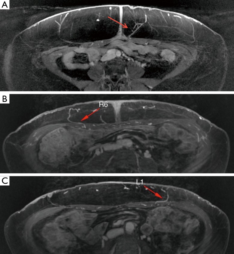
Axial MRA abdomen (25). (A) Arrow pointing to left paramuscular (septocutaneous) DIEP; (B) arrow pointing to right DIEP with short IM course; (C) arrow pointing to DIEP with a longer intramuscular course, and MRA provides helpful information that the perforator has a medial course before it courses caudal. MRA, magnetic resonance angiography; DIEP, deep inferior epigastric perforators.
Figure 4.
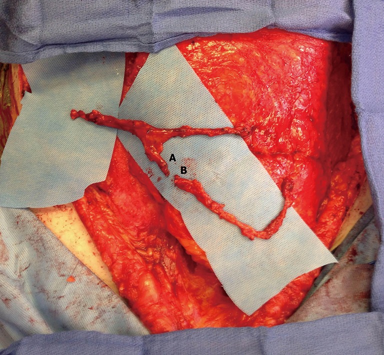
Photograph of a DIEP pedicle lateral branch (marked as A) adjacent to the origin of a second DIEP pedicle (marked as B) in preparation for microsurgical anastomosis, in which one DIEP flap will perfuse the second DIEP flap (flow-through flap) (25). DIEP, deep inferior epigastric perforators.
The location of the largest deep circumflex iliac perforators may also be identified and are measured in reference to the umbilicus (Figure 5). The perforator locations and course are then superimposed onto a volume rendered 3D reconstructed image, and this image is included in the report (Figure 6).
Figure 5.
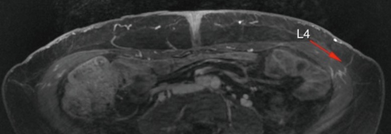
Axial MRA abdomen (25). Arrow points to left DCIP. MRA, magnetic resonance angiography; DIEP, deep inferior epigastric perforators.
Figure 6.
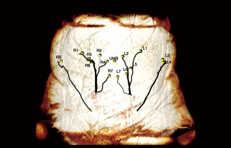
3D volume rendered MRA abdomen with DIEP, DCIP, and umbilicus locations, and vessel courses superimposed (25). MRA, magnetic resonance angiography; DIEP, deep inferior epigastric perforators.
The superficial inferior epigastric artery (SIEA) is evaluated and noted in the radiology report whether the SIEA shares a common origin with the superficial circumflex iliac vessels, as this will result in a larger caliber vessel for anastomosis.
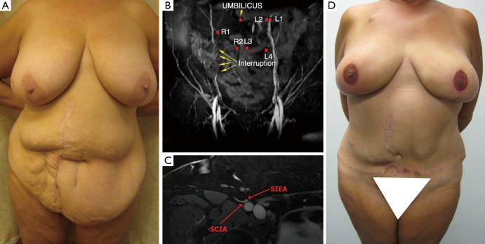
A clinical example of the utility of MRA in planning bilateral breast reconstruction using an abdominal perforator flap in a patient with a midline and two right paramedian scars from several bowel surgery operations is shown in Figure 7.
Figure 7.
(A) Photograph of patient for bilateral breast reconstruction with a midline and two right paramedian scars from several bowel surgery operations, who desired abdomen as donor site. The estimated hemi-abdominal flap volume was 1,000 g and estimated thigh flap volume was 325 g. (B) Coronal MRA abdomen. Arrows point to interruption in contrast in right DIEP pedicle secondary to previous abdominal surgery. (C) MRA abdomen. Common origin of SIEA and SCIA measuring 2.2 mm. (D) Postoperative photograph of patient with successful bilateral reconstruction with abdominal tissue (left breast SIEA flap and right breast DIEP flap) Adopted from (25). MRA, magnetic resonance angiography; DIEP, deep inferior epigastric perforators; SIEA, superficial inferior epigastric artery.
Spiral imaging may be employed by the radiologist to subtract venous flow to only view the SIEA (Figure 8), but this is not routinely done. The largest superficial inferior epigastric vein (SIEV) is identified on each hemiabdomen, and the location is measured from the umbilicus at 12 cm inferior to the umbilicus.
Figure 8.
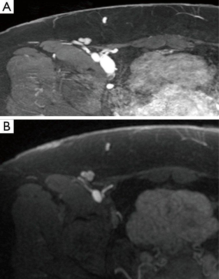
MRA abdomen (25). (A) Arterial and venous vessels enhanced; (B) venous vessel enhancement subtracted. MRA, magnetic resonance angiography.
The branching pattern of the perforating vessels within the subcutaneous fat is also evaluated. The two point Dixon methods for fat/water signal separation at 1.5 T and LAVA Flex at 3T are methods used by radiologists to suppress the fat signal, resulting in clearer images of DIEP arborization into the fat (Figure 9). In a unilateral reconstruction, it is helpful to see a medial row DIEP with branches crossing into the subcutaneous fat on the contralateral abdomen because zone III is more likely to be well-perfused, as seen in Figure 10. Figure 11 shows a DIEP with a very lateral course into the subcutaneous fat and a corresponding photograph of a patient with inadequate venous drainage of the medial tissue. A different perforator selection and/or indocyanine green injection would have prevented this. Usually DIEP branches can be visualized in close proximity with superficial inferior epigastric venous branches, which may theoretically provide improved venous drainage through connections (Figure 12).
Figure 9.
Axial MRA abdomen (25). (A) Inhomogenous fat suppression; (B) LAVA Flex used on a 3T resulting in improved visualization of DIEP arborization into the fat. MRA, magnetic resonance angiography; DIEP, deep inferior epigastric perforators.
Figure 10.
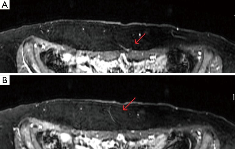
Axial MRA abdomen (25). Arrow pointing to left DIEP that has large branch crossing the midline to perfuse the contralateral abdominal tissue. MRA, magnetic resonance angiography; DIEP, deep inferior epigastric perforators.
Figure 11.
Axial MRA abdomen (25). (A) Short arrow points to location of DIEP exiting anterior rectus fascia. Long arrow points to approximate location that DIEP arborizes into the subdermal plexus. Note the very oblique course laterally. (B) Photograph postoperative day 5 after double DIEP flap in patient with midline abdominal scar. Circle is on medial flap that has decreased venous drainage. A lateral DIEP with very oblique lateral arborization was used. MRA, magnetic resonance angiography; DIEP, deep inferior epigastric perforators.
Figure 12.
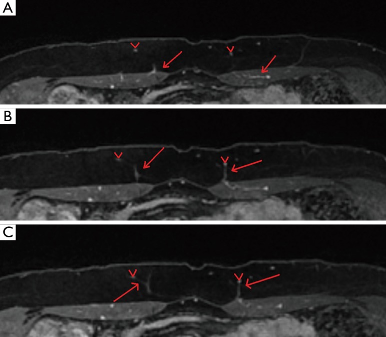
Axial MRA abdomen (25). “V” denotes SIEV, Arrows pointing to bilateral DIEPs. (A) Axial MRA; (B) left DIEP meeting SIEV; (C) right DIEP branch also meeting SIEV. MRA, magnetic resonance angiography; DIEP, deep inferior epigastric perforators; SIEV, superficial inferior epigastric vein.
Post-processing software is used by the radiologist to calculate projected abdominal flap volume (Figure 13). To increase accuracy of the estimated flap volume, a radiologist must first be educated in the typical markings and dimensions of an abdominal flap.
Figure 13.
(A) Axial MRA abdomen with subcutaneous fat manually outlined to calculate abdominal flap volume; (B) 3D volume rendered abdominal flap. MRA, magnetic resonance angiography (25).
Buttock
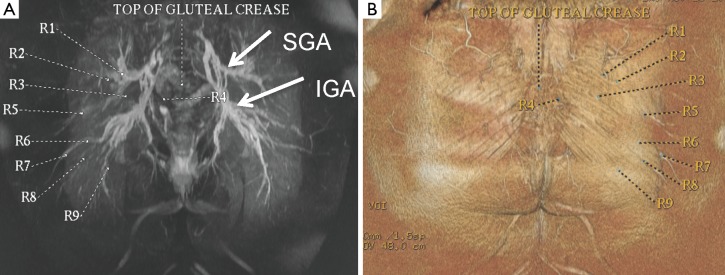
A vitamin E capsule is placed on the skin surface at the top of the gluteal crease as a reference point from which the perforator locations are measured. The largest perforators from the superior gluteal artery perforator (SGAP) and inferior gluteal artery perforator (IGAP) are identified. The locations of the perforators are calculated at the point of exiting the superficial fascia and this point is transposed on to the skin surface. Then, the distance of the perforator from the reference point is measured along the curved skin contour of the buttock (Figure 14). These measurements are taken with the patient in the prone position for increased accuracy because of the compliance of the gluteal tissue. Finally the perforator locations and reference point are superimposed onto a volume rendered 3D reconstruction of the buttock in the prone position so that the perforator location markings can be replicated preoperatively (Figure 15).
Figure 14.
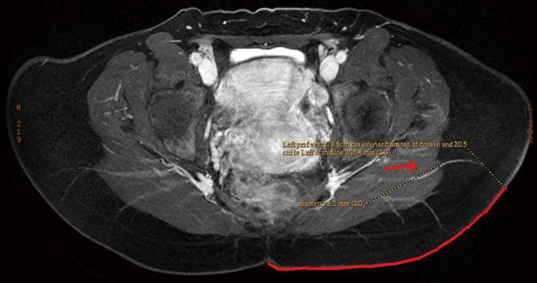
Axial MRA buttock with arrow pointing to gluteal perforator (25). Distance from midline reference point is calculated by measuring the distance along the curved skin surface with patient in the prone position to increase accuracy. Vessel caliber is calculated at superficial fascia exit point. MRA, magnetic resonance angiography.
Figure 15.
(A) Coronal MRA buttock with SGAP and IGAP locations and reference point location marked; (B) 3D volume rendered MRA buttock with perforator locations and reference point superimposed (25). MRA, magnetic resonance angiography; SGAP, superior gluteal artery perforator; IGAP, inferior gluteal artery perforator.
The placement of the buttock flap skin paddle is significantly influenced by optimal perforator location. The goal is to design a flap that incorporates the optimal perforator and a back-up option. Because there are usually many large caliber perforator options in the buttock, vessel location is an important determining factor in selecting the optimal vessel, taking scar location into account. Laterally positioned perforators will result in a longer pedicle, which is advantageous for flap insetting (Figure 16). In addition, more lateral flaps that may spare the central aesthetic unit in superior buttock flaps or the medial cushioning fat in lower buttock flaps. In bilateral flaps, an attempt is made to design flaps that will result in symmetrical scars by locating large perforators at a similar position bilaterally. As the familiarity of the radiologist increases with typical flap dimensions, the radiologist may calculate predicted upper and buttock flap volumes. Generally, an elliptical designed pattern measuring 6 cm in vertical dimension ×20 cm in transverse dimension is used by the radiologist.
Figure 16.
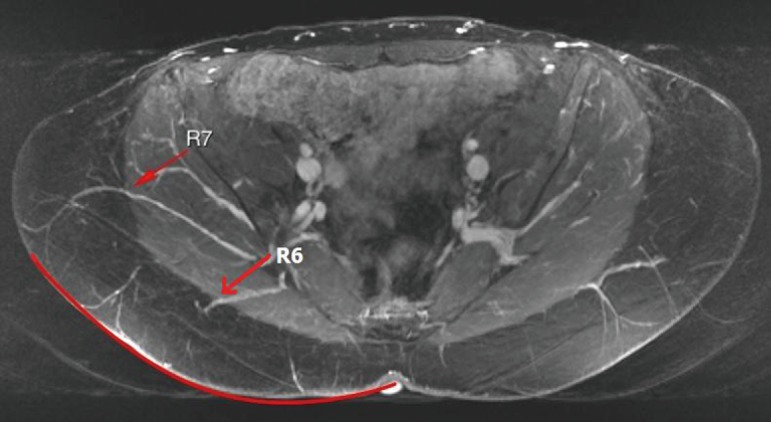
Axial MRA buttock showing two superior gluteal perforators (25). R7 is located more lateral than R6 and has a longer intramuscular course, yielding a longer pedicle. MRA, magnetic resonance angiography.
Thigh
The upper thigh is imaged from the mid gluteal region to the mid-thigh [about 12 cm caudal to the inferior gluteal crease (IGC)]. A transversely-oriented upper thigh flap is designed from medial to predominantly posterior thigh tissue to avoid the more anteriorly located lymphatic channels. A typical elliptical flap design for calculating thigh volume is 6 cm × 20 cm. The reference point from which the perforator locations are measured is the skin surface along the midline at the bottom of the gluteal crease. The locations of profunda artery perforators (PAP) flap are calculated at the point of exiting the superficial fascia. The perforators are also located in reference to the distance to the posterior edge of the gracilis muscle, to facilitate intraoperative identification of the perforator (Figure 17). Similar to gluteal artery perforators, the best PAP have an oblique course through the adductor magnus to yield a longer pedicle. Perforators that course more laterally adjacent to the femoral bone and then course cephalad into the gluteal vessels may be mistaken for PAP. As the patients are operated in the supine position, these gluteal perforators result in a difficult dissection with difficult exposure to yield adequate caliber and length pedicles. Occasionally, there is a large medial circumflex vessel perforating through the gracilis muscle or a paramuscular (septocutaneous) medial circumflex vessel that courses around the gracilis muscle (Figure 18). Perforator locations and courses and reference point are transposed onto the skin surface (Figure 19).
Figure 17.
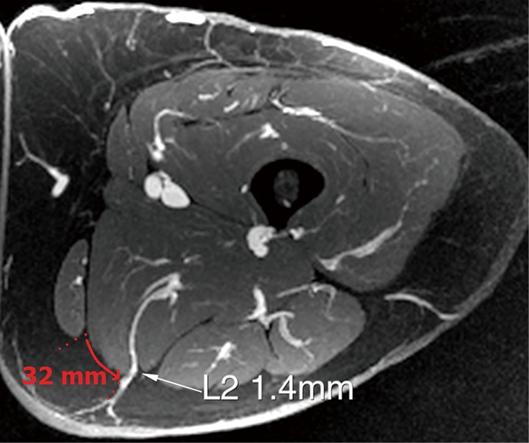
Axial MRA thigh with arrow pointing to profunda femoral artery perforator and distance from the posterior edge of the gracilius muscle (G) is measured (25). MRA, magnetic resonance angiography.
Figure 18.
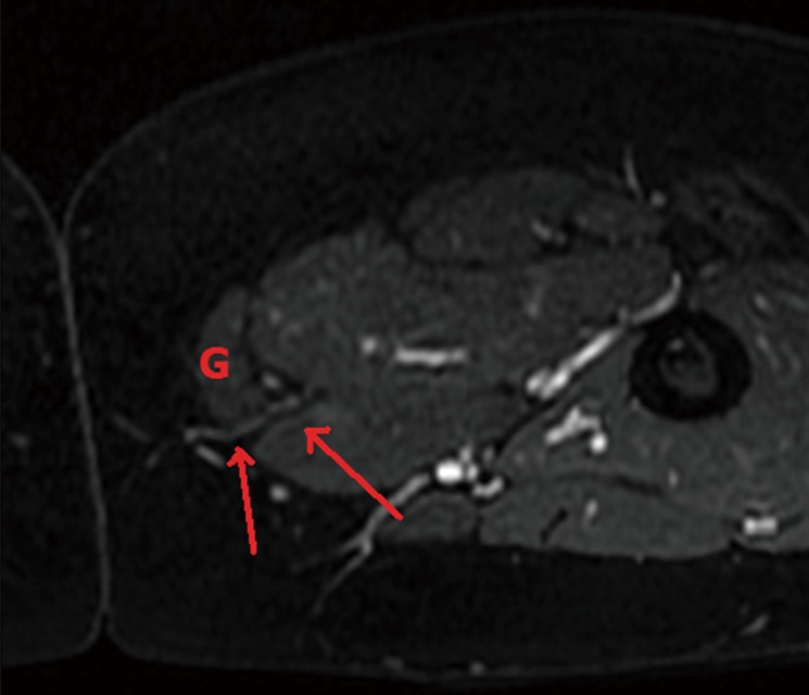
Axial MRA with arrows pointing to a septocutaneous medial circumflex femoral perforator that courses around the gracilis muscle (25). MRA, magnetic resonance angiography.
Figure 19.
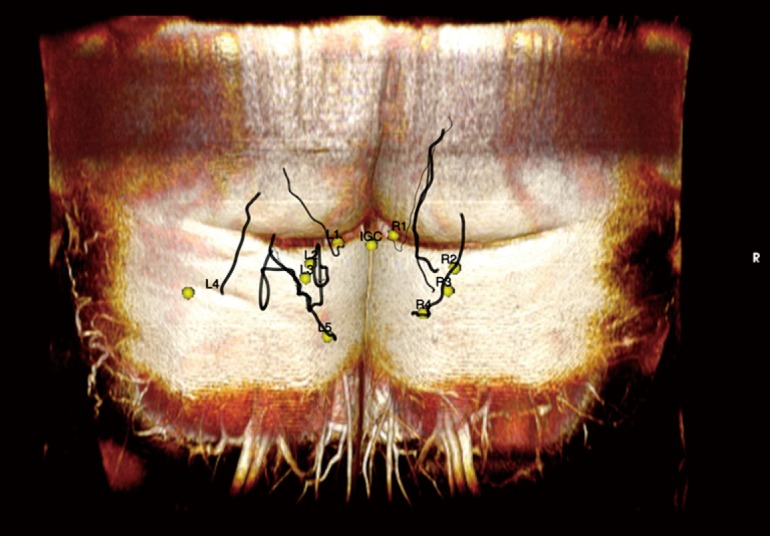
3D volume rendered MRA thigh with perforator locations and course and reference point at the IGC superimposed (25). MRA, magnetic resonance angiography; IGC, inferior gluteal crease.
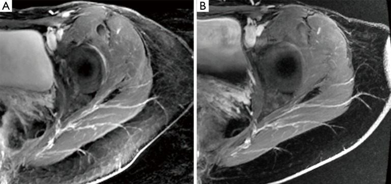
Sometimes, the lateral upper thigh (LTP flap) has a favorable fat deposition. A septocutaneous (paramuscular) lateral circumflex femoral artery perforators coursing around the tensor fasciae latae is measured in reference to the umbilicus and pubic tubercle (Figure 20). The anterior superior iliac spine (ASIS) was initially used as a reference point, but the ASIS can be difficult to palpate on some patients and lead to inaccuracies.
Figure 20.
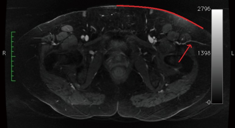
Axial MRA thigh. Arrow pointing to left septocutaneous lateral circumflex femoral perforator (25). MRA, magnetic resonance angiography.
Lower back
Lumbar artery perforators (LAP flap) are measured in reference to the midline upper gluteal crease. The limiting factor of this flap is the short pedicle length (Figure 21). Sometimes, LAP has an oblique course to yield a slightly longer pedicle. In general, these flaps are used as a back up option when the abdomen cannot be used, and the body habitus is not favorable for thigh or buttock flaps.
Figure 21.
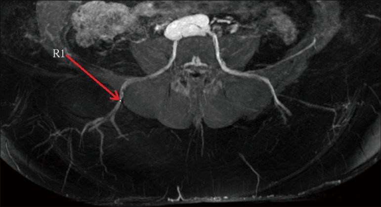
Axial MRA back. Arrow pointing to right lumbar perforator (25). MRA, magnetic resonance angiography.
Upper back
The chest is initially imaged with the patient in the supine position and the arms abducted to avoid compression of the lateral chest soft tissue. In patients with large body mass imaging for bilateral reconstruction, each side can be imaged separately so that one arm can be abducted at a time. It may be necessary for patients with a greater volume of upper arm fat to raise their arms and rest their hands on their head. Images should also be obtained of patients in the lateral decubitus position with the arm raised. Most radiology technicians are not aware that patients are positioned in the lateral decubitus position for the surgical reconstruction and part of the preoperative marking, and are not accustomed to scanning patients in this position. Measurements change significantly with the patient’s position and arm position. Thus, it is crucial for the radiologist to communicate the patient’s position in the series that the measurements are taken from. The radiologist should be aware that preoperatively a patient may need to be turned to the lateral decubitus position to mark posteriorly located perforators, and thus this series should be used for posteriorly located perforator measurements. The reference point is the skin surface at the sternal notch. The locations of thoracodorsal and internal mammary artery perforators are measured from a reference point at the sternal notch skin surface (Figure 22) and transposed onto the skin surface (Figure 23). Thoracodorsal artery perforators (TDAP) usually yield a longer pedicle, which is advantageous for insetting the flap.
Figure 22.
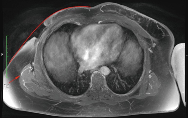
Axial MRA chest in a patient with a radiated open left chest wound. Arrow points to large thoracodorsal artery perforator (25). MRA, magnetic resonance angiography.
Figure 23.
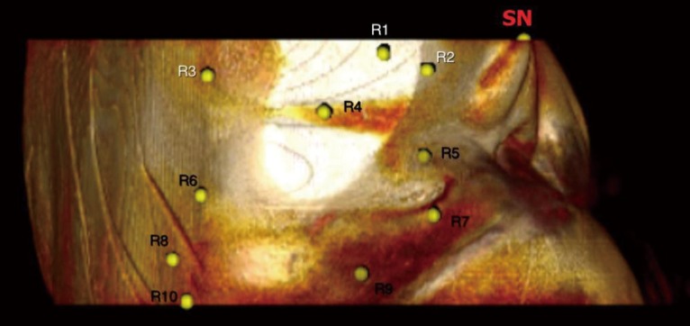
3D volume rendered MRA chest lateral decubitus with perforator locations and reference point at the sternal notch (SN) marked (25). MRA, magnetic resonance angiography.
Conclusions
The tremendous anatomic variability in the vascular system can make perforator flap breast reconstruction challenging for surgeons at all experience levels. Accurate preoperative anatomic vascular imaging enables optimal perforator selection and improves flap design. Shifting the brunt of the perforator selection process preoperatively improves operating efficiency, which can result in reduced operating time, reduced general anesthesia requirements, and potentially increased flap success (10,11,13). MRA is in our view the preoperative method of choice due to the absence of radiation exposure or iodinated contrast agents, and the ability for serial imaging acquisitions to visualize multiple donor sites with the patient in different positions in one examination.
Acknowledgements
I would like to thank our radiologists led by Dr. Martin Prince, and his dedicated fellows, Drs. Nanda Deepa Thimmappa, Jin Ah Kim, and Mukta Agrawal.
Footnotes
Conflicts of Interest: The authors have no conflicts of interest to declare.
References
- 1.Masia J, Clavero JA, Larrañaga JR, et al. Multidetector-row computed tomography in the planning of abdominal perforator flaps. J Plast Reconstr Aesthet Surg 2006;59:594-9. [DOI] [PubMed] [Google Scholar]
- 2.Rozen WM, Phillips TJ, Ashton MW, et al. Preoperative imaging for DIEA perforator flaps: a comparative study of computed tomographic angiography and Doppler ultrasound. Plast Reconstr Surg 2008;121:9-16. [DOI] [PubMed] [Google Scholar]
- 3.Brenner DJ, Hall EJ. Computed tomography--an increasing source of radiation exposure. N Engl J Med 2007;357:2277-84. [DOI] [PubMed] [Google Scholar]
- 4.Stein R. Too much of a good thing? The growing use of CT scans fuel medical concerns regarding radiation exposure. Washington Post 2008; F1.
- 5.Safety in medical imaging. American College Radiology Radiological Society North America, Inc. Available online: www.radiologyinfo.org/en/safety/index.cfm?pg=sfty_xray
- 6.Varnholt H. Computed tomography and radiation exposure. N Engl J Med 2008;358:852; author reply 852-3. [PubMed] [Google Scholar]
- 7.Katayama H, Yamaguchi K, Kozuka T, et al. Adverse reactions to ionic and nonionic contrast media. A report from the Japanese Committee on the Safety of Contrast Media. Radiology 1990;175:621-8. [DOI] [PubMed] [Google Scholar]
- 8.Parfrey P. The clinical epidemiology of contrast-induced nephropathy. Cardiovasc Intervent Radiol 2005;28:S3-11. [DOI] [PubMed] [Google Scholar]
- 9.Shellock FG, Crues JV. MR procedures: biologic effects, safety, and patient care. Radiology 2004;232:635-52. [DOI] [PubMed] [Google Scholar]
- 10.Vasile JV, Newman T, Rusch DG, et al. Anatomic imaging of gluteal perforator flaps without ionizing radiation: seeing is believing with magnetic resonance angiography. J Reconstr Microsurg 2010;26:45-57. [DOI] [PubMed] [Google Scholar]
- 11.Greenspun D, Vasile J, Levine JL, et al. Anatomic imaging of abdominal perforator flaps without ionizing radiation: seeing is believing with magnetic resonance imaging angiography. J Reconstr Microsurg 2010;26:37-44. [DOI] [PubMed] [Google Scholar]
- 12.Newman TM, Vasile J, Levine JL, et al. Perforator flap magnetic resonance angiography for reconstructive breast surgery: a review of 25 deep inferior epigastric and gluteal perforator artery flap patients. J Magn Reson Imaging 2010;31:1176-84. [DOI] [PubMed] [Google Scholar]
- 13.Vasile JV, Newman TM, Prince MR, et al. Contrast-enhanced magnetic resonance angiography. Clin Plast Surg 2011;38:263-75. [DOI] [PubMed] [Google Scholar]
- 14.Neil-Dwyer JG, Ludman CN, Schaverien M, et al. Magnetic resonance angiography in preoperative planning of deep inferior epigastric artery perforator flaps. J Plast Reconstr Aesthet Surg 2009;62:1661-5. [DOI] [PubMed] [Google Scholar]
- 15.Masia J, Kosutic D, Cervelli D, et al. In search of the ideal method in perforator mapping: noncontrast magnetic resonance imaging. J Reconstr Microsurg 2010;26:29-35. [DOI] [PubMed] [Google Scholar]
- 16.Dillman JR, Ellis JH, Cohan RH, et al. Frequency and severity of acute allergic-like reactions to gadolinium-containing i.v. contrast media in children and adults. AJR Am J Roentgenol 2007;189:1533-8. [DOI] [PubMed] [Google Scholar]
- 17.Niendorf HP, Alhassan A, Geens VR, et al. Safety review of gadopentetate dimeglumine. Extended clinical experience after more than five million applications. Invest Radiol 1994;29:S179-82. [DOI] [PubMed] [Google Scholar]
- 18.FDA Drug Safety Communication: New warnings for using gadolinium-based contrast agents in patients with kidney dysfunction. Available online: http://www.fda.gov/Drugs/DrugSafety/ucm223966.htm
- 19.Cowper SE. The International Center for Nephrogenic Systemic Fibrosis Research (ICNSFR). Available online: http://www.icnfdr.org/
- 20.Scheinfeld NS, Elston DM. Nephrogenic fibrosing dermopathy. Available online: http://www.emedicine.com/derm/topic934.htm
- 21.Lauffer RB, Parmelee DJ, Dunham SU, et al. MS-325: albumin-targeted contrast agent for MR angiography. Radiology 1998;207:529-38. [DOI] [PubMed] [Google Scholar]
- 22.Ersoy H, Jacobs P, Kent CK, et al. Blood pool MR angiography of aortic stent-graft endoleak. AJR Am J Roentgenol 2004;182:1181-6. [DOI] [PubMed] [Google Scholar]
- 23.Zou Z, Kate Lee H, Levine JL, et al. Gadofosveset trisodium-enhanced abdominal perforator MRA. J Magn Reson Imaging 2012;35:711-6. [DOI] [PubMed] [Google Scholar]
- 24.Agrawal MD, Thimmappa ND, Vasile JV, et al. Autologous breast reconstruction: preoperative magnetic resonance angiography for perforator flap vessel mapping. J Reconstr Microsurg 2015;31:1-11. [DOI] [PubMed] [Google Scholar]
- 25.Vasile JV. Imaging for perforator flap breast reconstruction. In: Levine JL, Vasile JV, Chen CM, et al. editors. Perforator flap breast reconstruction. New York: Thieme Publishers, 2015. [Google Scholar]


