Abstract
Three-dimensional (3-D) scaffolds with intrinsic porous structures are desirable in various tissue regeneration applications. In this study, a unique method that combines thermally induced phase separation with a photocrosslinking process was developed for the fabrication of 3-D crosslinked polymer scaffolds with densely interconnected porous structures. Biodegradable poly(propylene fumarate)-co-poly(L-lactic acid) with crosslinkable fumarate bonds were used as the structural polymer material and a dioxane/water binary system was applied for the phase separation. By altering the polymer composition (9, 5 and 3 wt%), different types of scaffolds with distinct morphology, mechanical strength, degradation rate, cell growth and morphology, and extracellular matrix production were fabricated. These crosslinked 3-D porous scaffolds with tunable strength and biological responses show promise for potential applications in regenerative therapies, including bone and neural tissue engineering.
Introduction
Regenerative therapies offer a hopeful future for many difficult disease conditions. Much recent work has focused on development of complex tissue implants using patient autologous cells for regeneration of bone, tendon, ligament, muscle, and nerve.1–5 A significant challenge to developing such an implant is the re-creation of a scaffolding matrix on which progenitor cells may divide and produce a viable implant. Ideally, such a scaffold would promote cell adhesion, division and signaling dynamics, would exhibit biocompatibility, and would degrade over time into non-toxic byproducts.1 Both natural and synthetic biodegradable scaffolds have been developed and widely examined for their ability to address the needs of various tissue engineering strategies.4 It is clear that unique approaches must be taken to create scaffolding materials capable of properly meeting the needs of each new application. For example, neural engineering applications require much more pliable scaffolds and care must be taken to address development of excess connective tissue / fibrosis.6,7 In bone regeneration applications, scaffolds must exhibit high compressive modulus and stiffness in an effort to mimic natural bony structures.8 These application specific challenges have led to the creation of many unique natural and synthetic polymer and co-polymer systems that are each designed to fill a particular need for regenerative therapies.
The necessity for tissue regeneration in the clinic has led to the production and testing of many polymers such as polyethylene,9 poly(ε-caprolactone) (PCL),10–12 poly(ethylene glycol) (PEG),13 poly(L-lactic acid) (PLLA),14 poly(methyl methacrylate) (PMMA),15 and poly(propylene fumarate) (PPF).16,17 Among these biodegradable polymers, PLLA and copolymers were acknowledged to have favorable biodegradability, high rigidity, and excellent tissue affinities without exhibiting inflammatory reactions in animal studies.18,19 PPF, which contains crosslinkable fumarate bonds, can be crosslinked to form polymer network by photo or chemical crosslinking methods.20 Various types of PPF based copolymers or blends were evaluated in bone tissue engineering and good cell responses were demonstrated.21–23
A major challenge to scaffold engineering has been the ability of oxygen and nutrients to diffuse through the material enabling cell invasion and growth while maintaining structural integrity within the scaffold.24 To address this concern, strategies such as particle leaching, microsphere sintering, 3-D printing, electrospinning, and thermally induced phase-separation (TIPS) have been employed.25,26 Recently, our group has reported a facile route in producing a series of porous PPF-co-PLLA interconnected scaffold using TIPS techniques.27 This method exploits a dioxane/water binary system that induces phase separation of a homogenous polymer solution. Notably, the novel scaffold material created by this method has demonstrated excellent protein adsorption and high mechanical strength.
The present study further introduces a photocrosslinking step into the TIPS technique in order to obtain more stable and flexible porous scaffolds. A series of crosslinked PPF-co-PLLA interconnected porous scaffolds with varied polymer compositions were then fabricated by in situ UV photocrosslink in the thermally induced PPF-co-PLLA/dioxane/water/BAPO system. The morphological structures inside these crosslinked porous scaffolds were observed using scanning electron microscopy (SEM). Mechanical properties of these scaffolds including stress-strain curves and compressive modulus were evaluated by dynamic mechanical analysis. The surface wettability and hydrolytic degradation of the scaffolds in 0.1 M NaOH and pH 7.4 phosphate buffered saline (PBS) were examined with an immersion time of 10 days and 8 weeks, respectively. The cytotoxicity and capability in supporting cellular adhesion and proliferation for these PPF-co-PLLA scaffolds were evaluated using MC3T3 mouse pre-osteoblast cells. Further, the extracellular matrix collagen deposition by cells on these scaffolds was determined using Sirius Red staining method.
Experimental
Materials and characterization
Propylene glycol, fumaryl chloride, L-lactide ((3S)-cis-3,6-dimethyl-1,4-dioxane-2,5-dione), tin(II) 2-ethylhexanoate (Sn(Oct)2, 95%), Sirius red stain (Direct Red 80) and saturated picric acid solution were purchased from Sigma Aldrich Co. (Milwaukee, WI). Tetrahydrofuran (THF), 1,4-dioxane, dichloromethane and other solvents were purchased from Fisher (Pittsburgh, PA) and used as received. All other reagents/chemicals were purchased from Fisher or Sigma unless noted otherwise. The chemical structures of synthesized PPF and PPF-co-PLLA copolymers were confirmed by 1H NMR spectra on a 300 MHz Varian NMR using CDCl3 solvent. Molecular weights of synthesized polymers were determined by Viscotek GPCMax/VE 2001 gel permeation chromatography (GPC, Malvern Instruments, Inc.) with tetrahydrofuran (THF) as eluent.
Polymer synthesis
Poly(propylene fumarate) containing crosslinkable double bonds were synthesized from diethyl fumarate and 1,2-propylene glycol using zinc chloride as catalyst, as described previously.28 Dried PPF terminated with hydroxyl groups were then copolymerized with L-lactide monomer at 140 °C for 24 hours using stannous octoate (Sn(Oct)2) as catalyst, as reported in our previous study.27 The hydroxyl groups in PPF initiate the ring opening polymerization of L-lactide monomer. Further chain propagation resulted in a PLLA-b-PPF-b-PLLA triblock copolymer, which will be referred to as PPF-co-PLLA copolymer in this study. Obtained PPF-co-PLLA copolymer was then fully dissolved in methylene chloride and precipitated in diethyl ether to remove the unreacted monomers, then fully dried in vacuum. Purified PPF-co-PLLA triblock copolymer was calibrated by GPC to have number average molecular weight (Mn), weight average molecular weight (Mw) and polydispersity index (PDI) of 54730, 99730 and 1.82, respectively.
Crosslinked 3-D porous scaffolds fabrication
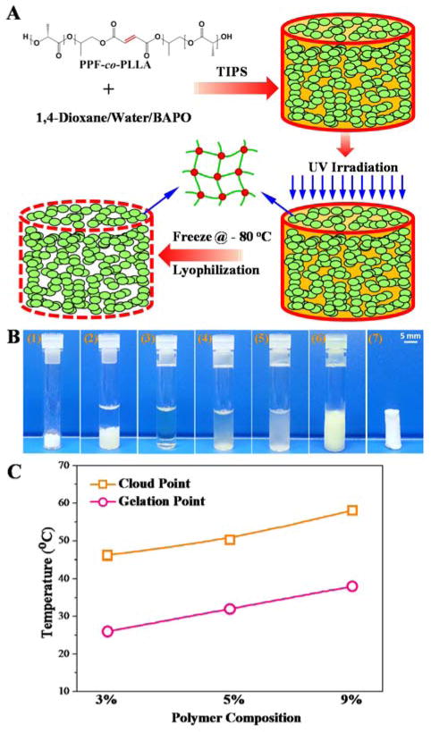
TIPS method was applied for the fabrication of crosslinked 3-D porous scaffolds, as described in Fig. 1A. Briefly, PPF-co-PLLA polymer with weight composition of 3, 5, or 9 wt% was mixed with a 1,4-dioxane/water (85/15, wt/wt) binary system in glass vials. The ternary polymer/dioxane/water mixtures were heated to 65 °C for 20 min allowing PPF-co-PLLA chains to dissolve, followed by 10 min incubation at 15 °C above the cloud point (Fig. 1B). The cloud-point was determined at the temperature when clear solutions became turbid and gelation temperatures were determined when solutions ceased to flow after the vials were inverted horizontally, as described in previous studies.27,29 In this study, the cloud and gelation point values are close to but slightly higher (Fig. 1C) than those reported in our previous study which used PPF-co-PLLA copolymers from different batches.27 Vials with dissolved PPF-co-PLLA were then cooled down at room temperature until clouding was observed, which indicates phase separation had occurred. Next, the samples were immediately transferred for UV irradiation (Black-Ray Model 100AP, Upland, CA) for 30 min to photocrosslink the polymer chains. The crosslinked samples were frozen at −80 °C to stabilize the shape of the pores and solvents were removed by lyophilization for 3 days to obtain the final 3-D porous scaffolds. The morphological structure of porous scaffolds was observed using scanning electron microscopy (SEM; S-4700, Hitachi Instruments, Tokyo, Japan).
Fig. 1.
(A) Schematic demonstration of the fabrication of crosslinked 3-D porous PPF-co-PLLA scaffolds using a phase separation method. (B) Detailed steps during the fabrication process: (1) weigh specific amount of PPF-co-PLLA and BAPO; (2) add solvents (dioxane/water); (3) dissolve copolymer at high temperature; (4) cool at room temperature until cloud point which indicates start of phase separation; (5) place immediately under UV irradiation for photocrosslinking; (6) freeze at − 80 °C; (7) dry by lyophilization. (C) The cloud point and gelation temperature for systems containing 3, 5, and 9 % of PPF-co-PLLA polymer.
Thermal and mechanical properties
Mechanical properties of crosslinked PPF-co-PLLA porous scaffolds were determined on a dynamic mechanical analyzer (DMA) (RSA-G2, TA instruments). Compressive strain-stress curves of the crosslinked porous polymer samples (~ 5 mm in diameter, 6–8 mm in length) were obtained at a strain rate of 0.01/s. Compressive moduli were calculated from the slope of the stress–strain curves in the linear region. Thermal properties of the crosslinked PPF-co-PLLA solid and porous scaffolds with varied polymer compositions (9%, 5%, 3 wt%) were determined using a differential scanning calorimeter (DSC) (TA Instruments). The samples were directly heated from room temperature to 200 °C with a heating rate of 10 °C/min.
Gel fraction, swelling ratio, porosity and degradation
To evaluate the crosslinking degree, gel fractions and swelling ratios of crosslinked PPF-co-PLLA scaffolds were determined in acetone. For each group, two crosslinked samples were weighted to get original mass (W0), then immersed in excess acetone. After 1 day, samples were taken out and weighed after remove of extra solvents quickly to obtain swelled mass (Ws). The swelled samples with solvent were then fully dried in vacuum for 2 days and weighed to obtain dry mass (Wd). The gel fractions and swelling ratios were calculated using the equations:
| (1) |
| (2) |
In order to determine the porosity of these crosslinked PPF-co-PLLA scaffolds, dried samples were weighed to obtain the sample mass, referred to as Ws. A pycnometer (or volumetric flask) filled with ethanol was weighed and recorded as W1. The porous scaffolds were then fully immersed into the bottle and ethanol started to invade and occupy the pores originally occupied by air. Extra ethanol was removed, then the bottle filled with ethanol and polymer sample was weighed and marked as W2. Finally, the porous PPF-co-PLLA scaffolds were taken out. The bottle with the remaining ethanol was weighed to obtain final mass of W3. The porosity of the porous scaffold was determined using the following equations according to previous reports.30–32
| (3) |
| (4) |
| (5) |
where ρ is the density of ethanol (0.789 g/mL), Vt is total volume, Vp is pore volume, and P is scaffold porosity.
The degradation of crosslinked PPF-co-PLLA scaffolds in 0.1 M NaOH and PBS solution was evaluated. For samples in 0.1 M NaOH solutions, the remaining mass of the scaffolds was measured until the scaffolds fully disappeared. For samples in PBS solutions, the mass loss during a time period of 8 weeks was determined.
Cell adhesion and morphology
Prior to cell studies, the crosslinked PPF-co-PLLA porous scaffolds (~12 × 2.5 mm diameter × height) were immersed in PBS for two weeks to remove the BAPO residue, followed by sterilization in 70% alcohol solution and complete drying under vacuum. MC3T3 pre-osteoblast cells were cultured in DMEM supplemented with 10% FBS in a 37 °C incubator with 95% relative humidity and 5% CO2. Following trypsinization, MC3T3 cells were suspended in DMEM, counted, and diluted to the desired concentration. For each scaffold sample, 0.5 mL of cell suspension was gently placed onto the scaffold surface (5 x 10⁴ cells per cm2) in 24-well tissue culture polystyrene (TCPS) plates and kept in the incubator for 2 hours, allowing cells to attach. After cell attachment, 0.5 mL of fresh medium was added to each well. DMEM was changed every day to ensure sufficient nutrition for cells growing in the scaffolds. After 1, 3, 5 and 14 days of culture, scaffolds were washed with PBS to remove unattached cells. Then the number of cells on these scaffolds was determined using MTS assay (CellTiter 96 Aqueous One Solution, Promega, Madison, WI) with a microplate reader detecting absorbance at 490 nm wavelength. For fluorescent MC3T3 cells cultured on the porous scaffolds were washed with PBS three times, fixed using 4% paraformaldehyde (PFA) solution, and permeabilised in 0.2% Triton X-100. Rhodamine-phalloidin (RP, Cytoskeleton Inc) was used to stain the cytoskeleton for 1 h at 37 °C and 4′,6-diamidino-2-phenylindole (DAPI) was used to stain cell nuclei at room temperature for 2 min. Stained MC3T3 cells were visualized and photographed on an Axiovert 25 Zeiss light microscope (Carl Zeiss, Germany). Cell area was determined using ImageJ software and average value from 20 cells growing on each scaffold was determined. After dehydration by critical point drying (CPD) method, MC3T3 cells on the porous scaffolds were observed by scanning electron microscopy (SEM; S-4700, Hitachi Tokyo, Japan).
Collagen production
After seeding with MC3T3 cells, the porous scaffolds with varied polymer compositions were cultured in a tissue culture incubator while changing cell media every 2 days. At 1 week and 2 weeks post-seeding, the total collagen production of MC3T3 cells on these scaffolds was evaluated using Sirius red staining method, as described in previous studies.33,34 Briefly, porous scaffolds with cells were washed three times with PBS and fixed by 4% paraformaldehyde (PFA) solution. Next, 1 mL of Sirius red stain solution (0.1% Direct Red 80 in saturated picric acid, Sigma-Aldrich) was added to each sample in a 24-well TCPS plate. After staining for 16 hours, scaffolds were washed with distilled water to remove excessive stain, and dehydrated by washing in 100% ethanol three times. After drying, stained scaffolds were weighed to obtain dried sample mass (Wm). Next, 1 ml of 0.2 M NaOH : methanol 1:1 solution was added to each sample to elute the stain for 15 min. The absorbance of the eluted solution was measured at 490 nm and divided by Wm to obtain absorbance per gram of dry polymer.
Statistical analysis
One-way analysis of variance (ANOVA) was applied for the statistical analysis of data from each group in this study. Groups that were calculated with p-value lower than 0.05 (p < 0.05) were considered to have statistical difference.
Results and discussion
Fabrication of crosslinked 3-D porous scaffolds
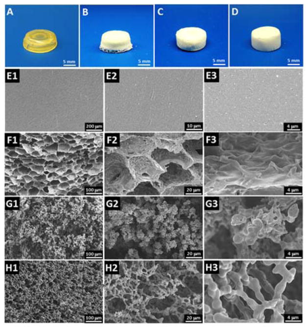
Phase separation is a widely applied technique in fabricating tissue engineering scaffolds.35 Here, the PPF-co-PLLA scaffolds were fabricated via the TIPS process in dioxane/water binary system combined with photocrosslinking and lyophilization. The phase separation parameters that affect macroporous structures of uncrosslinked scaffolds, including polymer concentration (1, 3, 5, 7, and 9%), dioxane/water ratio (83/17, 85/15, and 87/13 wt/wt), quench time (1, 4, and 8 min), and freeze temperature (−20, −80, and −196 °C), were investigated in our previous study.27 The current work has shown that after photocrosslinking, we could obtain a more stable porous network, which maintains the 3-D porous structure created by the phase separation process. The final crosslinked PPF-co-PLLA scaffolds were characterized by a white color flat solid, as seen from sample images in Fig. 2B, C and D for 9, 5 and 3% porous PPF-co-PLLA scaffolds, respectively. The crosslinked PPF-co-PLLA solid scaffolds, which were directly crosslinked in CH2Cl2 solution instead through the phase separation process, showed a firm structure with a lightly yellow color as is common for PPF networks (Fig. 2A).
Fig. 2.
Photographs of the crosslinked solid PPF-co-PLLA substrates (A) and 3-D porous scaffolds with varied polymer composition of (B) 9%, (C) 5% and (D) 3%. The internal structures observed by SEM for (E1–3) solid PPF-co-PLLA substrates and 3-D porous scaffolds with varied polymer composition of (F1–3) 9%, (G1–3) 5% and (H1–3) 3%.
SEM images demonstrated a smooth and flat surface for the solid substrates without pore structures (Fig. 2E1–3). The other three porous scaffolds were characterized to have highly interconnected open-pore microstructure, as demonstrated in Fig. 2F–H. The SEM images indicated that the microstructure characteristics of the scaffolds varied with the polymer composition. Both the PPF and PLLA segments dissolve well in 1,4-dioxane, while these components remain insoluble in water, resulting in relatively uniform scaffold microstructures after photocuring and lyophilization. As seen in Fig. 2F1–3, scaffolds fabricated with 9 polymers had interconnected and elongated open-pores. Thick pore struts with continuous pore walls were observed in higher magnification SEM images. Similar microstructure was reported for PLLA scaffolds which phase-separated from the 1,4-dioxane/water system in previous studies.36 However, when the polymer content in the system was reduced to 5 wt%, not enough polymer content could be accessed during phase separation thus a unique structure without obvious pore walls was observed (Fig. 2G1–3). When the polymer content was further reduced to 3 wt%, a more sparse, silk bead-like morphology was formed with fused beads surrounding large pores, as displayed in Fig. 2H1–3. This is a type of structure frequently observed in porous membranes fabricated using similar procedures.37,38 During this process, the cooling phase leads first to bead formation. With the solvent continues to leave under phase separation, particles were subsequently trapped in large spherical polymer-poor droplets. Further cooling process locks the small polymer beads around large solvent droplets to reach the final porous morphology inside the scaffolds.37,38 Varied polymer concentrations in the phase separation system could largely influence the bead formation and gathering process thus led to distinct structural morphologies, as demonstrated by SEM images in Fig. 2F–H.
In this study, 3% polymer concentration is the lowest content we report for creating a complete scaffold. We tried to fabricate concentrations as low as 2% and 1%, however, only debris not full scaffolds was created during the process. Higher polymer concentrations were also attempted, but the produced scaffolds were shrank as the pores began to close during the lyophilization process, as can be noted from Fig. S1. This phenomenon is believed to be largely caused by the relatively poor PPF-co-PLLA dispersion in the dioxane/water system under conditions of high polymer contents. Therefore, a polymer composition lower than 10% is suggested in the fabrication of PPF-co-PLLA copolymer porous scaffolds. High gel fractions with values of 97.3 ± 1.6, 88.0 ± 3.2, 86.5 ± 3.6 and 81.2 ± 4.7% were determined (Fig. S2) for solid and porous scaffolds with 9, 5 and 3% polymer composition porous scaffolds, respectively. This indicates the photocrosslinking of all scaffolds were successful and resulted sufficient networks in the scaffolds. The porosity determined for these crosslinked porous scaffolds were 77.9 ± 2.0, 83.4 ± 3.5 and 91.9 ± 4.0 % for 9, 5 and 3% polymer composition porous scaffolds, respectively. DSC curves showed crystallized peaks for porous scaffolds with no peaks for solid scaffolds. This indicates that PPF-co-PLLA chains undergo full crystallization process in solid scaffolds while keep partially non-crystallized in the porous scaffolds (Fig. S3).
Surface wettability
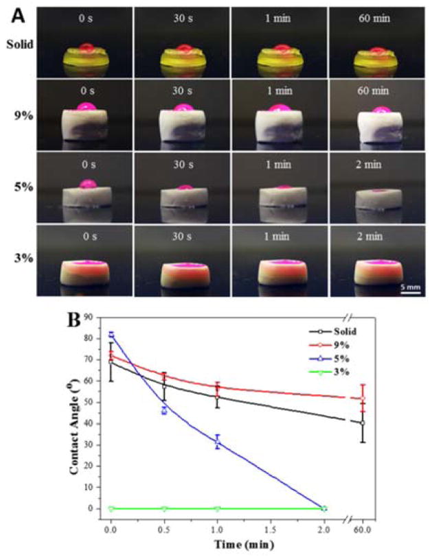
The water wettability of these scaffolds was evaluated by dropping a red-dyed, de-ionized water solution on the scaffold surface. The change of water droplets at different time points was captured and the water contact angles were read. As demonstrated in Fig. 3A, the porous scaffolds with lower polymer content (from 9% to 3%) featured hydrophilic characteristics with an accelerate uptake of fluid. Solid scaffolds and porous scaffolds with high polymer content retained the droplet through the 60 min time point. It is noticeable from Fig. 3A that the 9% porous scaffolds with pore morphology on the surface have even better capability to retain the droplet than the solid scaffolds with flat surfaces. The water contact angle obtained and averaged from droplet images showed higher water contact angles of 72.0 ± 1.8° for the 9% porous scaffolds, which were increased over that of solid samples (68.8 ± 9.0°). After 60 min, solid samples were characterized to have contact angles of 40.3 ± 9.2°, whereas higher values (51.8 ± 6.3°) were determined for the 9% porous scaffold (Fig. 3B). It is previously reported that substrate wettability can be affected by surface topography.39,40 Micro/nano structured surfaces could generate air pockets between substrate and water droplets, and thus enhance hydrophobicity of polymer scaffolds.40
Fig. 3.
(A) Light images and (B) contact angle values of water droplets on the solid and porous scaffolds.
For the 5% porous scaffolds, an initial contact angle of 81.8 ± 1.0° was determined. However, the droplet was quickly adsorbed by the scaffolds in ~2 minutes due to the penetration of water within the scaffold (Fig. 3A). With even lower polymer content, the 3% porous scaffolds adsorbed water immediately after the droplet reached the surface. We hypothesize that this is largely due to the interconnected structures inside these 5% and 3% scaffolds, which easily cause air leakage, and thus do not generate stable air pockets to hold the droplet. This penetration resulted in a larger contact surface area for DMEM thus are expected to allowing more serum protein adsorptions onto the scaffold surfaces during cell culture process.
Mechanical properties and degradation
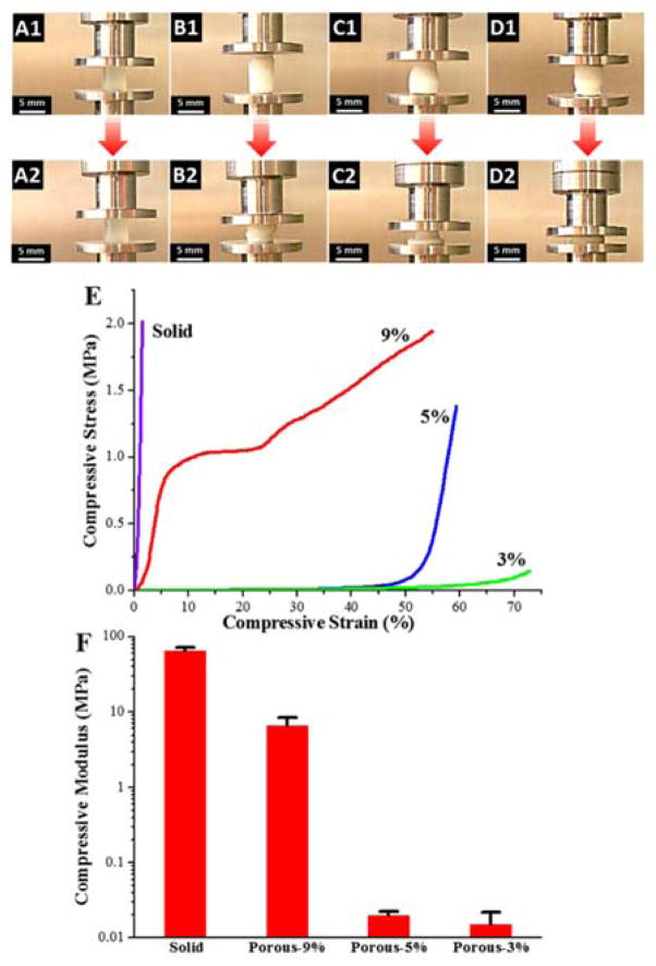
The mechanical properties of the crosslinked PPF-co-PLLA scaffolds were determined by compressive testing on a dynamic mechanical analyzer (DMA). As can be seen from the sample images in Fig. 4A–D, under a maximum compressive force of ~32 N, all of the crosslinked PPF-co-PLLA samples were observed to be deformed. However, the extent of deformation was strikingly different between solid and porous groups. The solid crosslinked PPF-co-PLLA scaffolds without porous structures showed only slight deformation (Fig. 4A1–A2) with maximum strain (εmax) of 1.4 ± 0.2% determined from the stress-strain curves (Fig. 4B). However, obvious deformation was observed in the porous scaffolds with polymer composition of 9% (Fig. 4B1–B2), 5% (Fig. 4C1–C2), and 3% (Fig. 4D1–D2). The εmax for 9, 5, and 3% porous scaffolds was calculated to be 51.9 ± 4.3, 60.0 ± 0.9 and 78.9 ± 8.1%, respectively.
Fig. 4.
Dimensional changes during compressive testing for solid scaffolds (A1–A2) and 9% (B1–B2), 5% (C1–C2) and 3% (D1–D2 porous scaffolds. (E) Stress-strain curves and (F) compressive modulus of the solid and porous scaffolds with polymer compositions of 9, 5 and 3%.
The representative stress-strain curves of these scaffolds are presented in Fig. 4E. As can be noted, the solid, 5% and 3% scaffolds exhibited stress-strain curves that were nearly in linear trend, whereas the 9% porous scaffolds were found to have a more typical, multi-component stress-strain curve (Fig. 4E). Stress-strain curve for 9% porous scaffold is composed of three regions, including a linear region, a flat region, and a densified region, as consistent with previous reports.36,41 The linear elastic region (0–10%) demonstrates the linear elastic deformation of the porous scaffold whereas the flat region (10–25%) denotes the gradual deformation at larger strain. The ultimate densified region from 25% to εmax occurs when the pore walls are increasingly collapsed under strong compressive force, which can lead to solidification of porous scaffolds and in turn result in a sharp increase in stress. For 5% and 3% porous scaffolds, no plateau region was detected up to their εmax. In addition, a variance in modulus from several kPa to MPa could be achieved by varying the polymer composition in the porous scaffolds, as demonstrated in Fig. 4F. This property is useful for the fabrication of scaffolds with specific, desired mechanical properties for a large variety of tissue engineering applications, e.g., from nerve to bone tissue engineering.
The biodegradability is a critical parameter for the evaluation of polymeric scaffolds aiming at different tissue engineering applications.42 At initial stage of implantation, scaffolds are required to have certain mechanical strength to meet the mechanical requirement of the defect site and to support cell attachment and proliferation. However, at later times, scaffolds are expected to self-degrade in vivo thus leaving space for the development of new tissues and/or gradual load transfer to the newly formed tissue. The desired degradation time varies according to different application purpose; some have suggested a time period of 3–9 months would be preferable for scaffolds aiming at bone tissue regeneration.43 However, the degradation of PLLA polymer takes far more than a few months, as it is typically reported to be longer than 24 months.44 In a clinical study, crystalline solid PLLAs were found to be retained 5.7 years post-implantation within the patient’s body.45
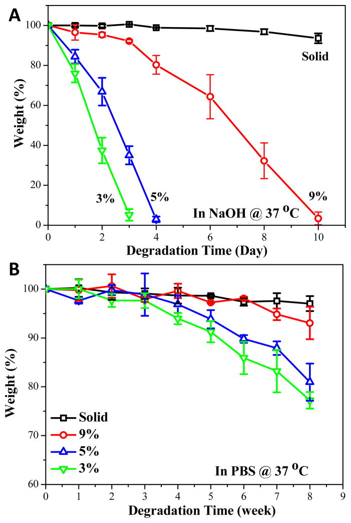
The degradation of solid and porous scaffolds was evaluated and compared in both 0.1 M NaOH and PBS solution. As can be noted from Fig. 5A, solid crosslinked PPF-co-PLLA substrates only had a slight weight loss in 0.1 M NaOH solution in a time frame of 10 days. However, polymer composition appeared to be the main factor which controlled the degradation rate. The 9% porous scaffolds fully degraded in 10 days whereas the 5% and 3% porous scaffolds degraded in 4 and 3 days, respectively. This result from the accelerated degradation study using 0.1 M NaOH solution clearly demonstrated that porous scaffolds could degrade much faster than their solid counterparts. In addition, the degradation time is directly related to the polymer composition in the scaffold, as lower polymer content gains much faster degradation rate. The degradation rate in PBS is much lower than that in 0.1 M NaOH solution. Up to an evaluation time period of 8 weeks, the solid substrates kept most of their original mass while the porous scaffolds lost extensive weight, with the most weight loss occurring in the 3% porous scaffolds (Fig. 5B). These degradation rates in PBS confirm our results from the accelerated study with 0.1 M NaOH. Both degradation conditions demonstrate the increased biodegradability for porous scaffolds compared to that of solid substrates. This phenomenon may be due to the pore structures inducing transportation of solution into the interior of porous scaffolds, thus facilitating a quicker bulk degradation process.
Fig. 5.
Percent weight loss over time of solid and porous scaffolds with different polymer compositions in (A) 0.1 M NaOH solution and (B) PBS solution at 37 °C.
Cell growth, spreading and morphology
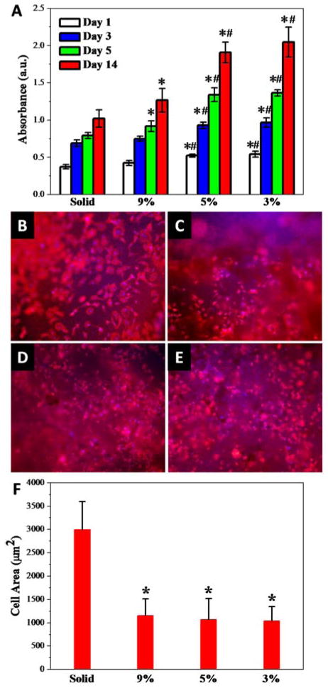
MC3T3 pre-osteoblast cell response to the photo-crosslinked PPF-co-PLLA solid substrates with flat topography or porous scaffolds with pore structures was evaluated. All the four types of scaffolds demonstrated excellent biocompatibility and no cytotoxicity effects to MC3T3 cells (Fig. S4). The porous scaffolds supported significantly increased MC3T3 cell growth, compared to the flat substrates at 1, 3, 5 and 14 days post-seeding, as shown in Fig. 6A. For the porous scaffolds, cell growth varied largely on scaffolds with different polymer compositions. The 5% and 3% porous scaffolds showed significantly higher cell numbers after 1 day post-seeding. From day 3 to day 5, the cells on solid substrates and 9% porous scaffolds showed a limited increase in cell number, which may have been due to the confluence of cells on the substrate surface. However, for the 5% and 3% porous scaffolds with low polymer composition, the cell numbers increased significantly. The same trend was observed for MC3T3 cell numbers with prolonged culture time up to 14 days on these solid or porous substrates.
Fig. 6.
(A) MC3T3 cell numbers determined at 1, 3, 5 and 14 days post-seeding on the scaffolds. Fluorescence images of MC3T3 cells cultured on the solid (B) and porous scaffolds with (C) 9%, (D) 5% and (E) 3% polymer composition at 1 day post-seeding. Red (RP). Blue (DAPI). (F) Cell spreading area on solid and porous scaffolds. *: p < 0.05 relative to the solid substrate; #: p < 0.05 relative to 9% porous scaffolds.
This phenomenon may be a result of the low polymer content in the scaffold leaving substantial space for the cells to grow into. Therefore, for these scaffolds, cell proliferation is not limited to the surface area, but instead cells are able to penetrate into the porous spaces within the scaffolds. These results indicated that the porous structure provided a more preferable environment for cell growth, compared to that of the solid substrates. The introduction of a bioceramic component into polymer networks was reported to enhance mechanical properties and further improve cell adhesion, proliferation, and osteoblastic differentiation on polymeric scaffolds aiming at bone tissue engineering.46,47 Strengthened 3-D porous polymer/bioceramic scaffolds may potentially be fabricated by further incorporating a biocompatible rigid component, e.g., hydroxyapatite, into the phase separation system and crosslink them within the polymer networks.
Cell spreading on substrates is acknowledged to be closely related to cell division and thus proliferation.48,49 In order to observe cell morphology and evaluate cell spreading area, MC3T3 cells were fixed and stained with rhodamine-phalloidin (F-actin) and DAPI (cell nuclei) after one day culture on the scaffolds. The MC3T3 cell morphology can be clearly seen in the fluorescent images taken on the solid (Fig. 6B) and porous scaffolds with polymer composition of 9% (Fig. 6C), 5% (Fig. 6D) and 3% (Fig. 6E). MC3T3 cultured on solid substrates with flat surfaces showed markedly increased spreading, while cells on porous scaffolds appeared in a more condensed morphology. Quantitative cell area was calculated from fluorescent cell images at 1 day post-seeding. As seen in Fig. 6F, the solid substrate with flat surfaces was determined to have the largest cell areas of 2991 ± 604 μm2. However, on porous scaffolds with discontinued surface pore topography, the cell spreading is inhibited, with cell areas of 1157 ± 357, 1070 ± 453 and 1040 ± 308 μm2 determined for 9%, 5% and 3% porous scaffolds, respectively.
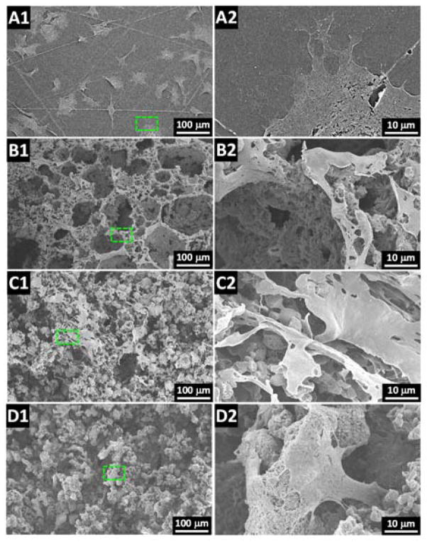
To substantiate and further investigate the cell morphology from the fluorescent images, SEM imaging of dehydrated MC3T3 cultures on the scaffolds was conducted. As found in Fig. 7A–D, the cell spreading viewed by SEM on these substrates was consistent with the calculated cell area results from the fluorescent cell imaging. For MC3T3 cells on solid substrates, all cells appeared to spread well (Fig. 7A1) with free development of protrusions (Fig. 7A2). In comparison, cell spreading was largely confined on porous scaffolds with cells sitting on the ridge of the pore structures for 9% porous scaffolds (Fig. 7B1–B2). For 5% and 3% porous scaffolds, inhibited spreading was also observed with cells that appeared stretched on the porous surface (Fig. 7C1–C2) or started to penetrate into the interior space of the porous scaffolds (Fig. 7D1–D2).
Fig. 7.
SEM images of MC3T3 cells cultured on the (A1–A2) solid and porous scaffolds with (B1–B2) 9%, (C1–C2) 5% and (D1–D2) 3% polymer composition.
Extracellular matrix development
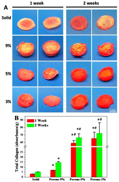
Extracellular matrix (ECM) development is critical for cell proliferation and tissue development.50,51 Collagen is an importance component of the ECM, which can be stained and visualized by the Sirius red staining method. In this work, collagen accumulation in the solid and porous scaffolds after 1 week and 2 weeks of incubation with MC3T3 cells was evaluated. As can be seen from Fig. 8A, after one week’s incubation with cells, the solid samples were stained with a mild red color due to collagen deposition on the scaffold surface. In contrast, much stronger collagen staining was found for porous scaffolds both on the surface and in the interior of the scaffolds, particularly for 5% and 3% porous scaffolds. After 2 weeks incubation, the collagen accumulation increased for all the scaffolds with the same trend of higher collagen content on porous scaffolds, as indicated by the intensified red color (Fig. 8A).
Fig. 8.
(A) MC3T3 extracellular matrix deposition in solid and porous scaffolds visualized by Sirius red staining after 1 and 2 week days of culture in DMEM. (B) Total collagen amounts per gram of scaffolds determined from Sirius red staining after 1 week and 2 weeks in culture.
To make a quantitative comparison of total collagen production per gram of scaffolds, the Sirius red stain was washed down from these scaffolds using NaOH/MeOH solution. The absorbance of collected Sirius red solution was determined using a microplate reader. The optical density was then normalized to scaffold mass. As demonstrated in Fig. 8B, absorbance of Sirius red stain was significantly enhanced in the porous scaffolds compared to the solid scaffolds (p < 0.05). In addition, with the altering of polymer composition in the porous scaffolds, the collagen production from in vitro culture varied dramatically. The 5% and 3% porous scaffolds showed significantly (p < 0.05) higher content of collagen accumulated in the scaffold than that of 9% porous scaffolds. These results indicate that the low polymer composition scaffolds could allow larger spaces for cells to penetrate, thus encouraging production of ECM proteins, which is strongly desirable for scaffolds aimed at tissue engineering applications.
Conclusions
This study details the preliminary development and testing of TIPS fabricated crosslinked porous PPF-co-PLLA scaffolds with tunable mechanics for tissue engineering applications. The mechanical strengths, porosities, surface wettabilities and biodegradation rates for these scaffolds could be effectively modulated by adjusting the polymer composition inside the scaffold. Biological studies showed that these scaffolds were biocompatible to MC3T3 cells, and cell behaviors including spreading, proliferation and collagen deposition can be well tuned by altering the scaffold formulations. In summary, the crosslinked porous PPF-co-PLLA scaffolds reported in this work present an exciting advancement towards novel, tailorable scaffolds for applications in regenerative therapies.
Supplementary Material
Acknowledgments
This work was supported by the Mayo Foundation and NIH grants R01 AR56212 and R01 EB03060.
Footnotes
Electronic Supplementary Information (ESI) available: [Supporting information]. See DOI: 10.1039/x0xx00000x
References
- 1.Porter JR, Ruckh TT, Popat KC. Biotechnol Prog. 2009;25:1539–1560. doi: 10.1002/btpr.246. [DOI] [PubMed] [Google Scholar]
- 2.Font TS, Balmayor ER, Van Griensven M. Adv Drug Deliv Rev. 2015 doi: 10.1016/j.addr.2015.03.004. [DOI] [PubMed] [Google Scholar]
- 3.Caudwell M, Crowley C, Khan WS, Wong JM. Curr Stem Cell Res Ther. 2014;10:11–18. doi: 10.2174/1574888x09666140710101435. [DOI] [PubMed] [Google Scholar]
- 4.Liu X, Wang S. In: Encyclopedia of Biomedical Polymers and Polymeric Biomaterials. Mishra M, editor. Taylor & Francis; New York, USA: 2015. pp. 7957–7971. [Google Scholar]
- 5.Daly W, Yao L, Zeugolis D, Windebank A, Pandit A. J R Soc Interface. 2012;9:202–221. doi: 10.1098/rsif.2011.0438. [DOI] [PMC free article] [PubMed] [Google Scholar]
- 6.Chen BK, Knight AM, Madigan NN, Gross L, Dadsetan M, Nesbitt JJ, Rooney GE, Currier BL, Yaszemski MJ, Spinner RJ, Windebank AJ. Biomaterials. 2011;32:8077–8086. doi: 10.1016/j.biomaterials.2011.07.029. [DOI] [PMC free article] [PubMed] [Google Scholar]
- 7.Ruschel J, Hellal F, Flynn KC, Dupraz S, Elliott DA, Tedeschi A, Bates M, Sliwinski C, Brook G, Dobrindt K, Peitz M, Brüstle O, Norenberg MD, Blesch A, Weidner N, Bunge MB, Bixby JL, Bradke F. Science. 2015;348:347–352. doi: 10.1126/science.aaa2958. [DOI] [PMC free article] [PubMed] [Google Scholar]
- 8.Holy CE, Fialkov J, Davies JE, Shoichet MS. J Biomed Mater Res A. 2003;65:447–453. doi: 10.1002/jbm.a.10453. [DOI] [PubMed] [Google Scholar]
- 9.Paxton JZ, Donnelly K, Keatch RP, Baar K. Tissue Eng Part A. 2009;15:1201–1209. doi: 10.1089/ten.tea.2008.0105. [DOI] [PubMed] [Google Scholar]
- 10.Thibault RA, Scott Baggett L, Mikos AG, Kasper FK. Tissue Eng Part A. 2010;16:431–440. doi: 10.1089/ten.tea.2009.0583. [DOI] [PMC free article] [PubMed] [Google Scholar]
- 11.Cai L, Foster CJ, Liu X, Wang S. Polymer. 2014;55:3836–3845. [Google Scholar]
- 12.Henry MG, Cai L, Liu X, Zhang L, Dong J, Chen L, Wang Z, Wang S. Langmuir. 2015;31:2851–2860. doi: 10.1021/la504994e. [DOI] [PubMed] [Google Scholar]
- 13.Nicolas J, Mura S, Brambilla D, Mackiewicz N, Couvreur P. Chem Soc Rev. 2013;42:1147–1235. doi: 10.1039/c2cs35265f. [DOI] [PubMed] [Google Scholar]
- 14.Armentano I, Dottori M, Fortunati E, Mattioli S, Kenny JM. Polym Degrad Stabil. 2010;95:2126–2146. [Google Scholar]
- 15.Xing ZC, Han SJ, Shin YS, Koo TH, Moon S, Jeong Y, Kang IK. J Biomater Sci Polym Ed. 2013;24:61–76. doi: 10.1163/156856212X623526. [DOI] [PubMed] [Google Scholar]
- 16.Wang S, Lu L, Yaszemski MJ. Biomacromolecules. 2006;7:1976–1982. doi: 10.1021/bm060096a. [DOI] [PMC free article] [PubMed] [Google Scholar]
- 17.Yan J, Li J, Runge MB, Dadsetan M, Chen Q, Lu L, Yaszemski MJ. J Biomater Sci Polym Ed. 2011;22:489–504. doi: 10.1163/092050610X487765. [DOI] [PMC free article] [PubMed] [Google Scholar]
- 18.Dhandayuthapani B, Yoshida Y, Maekawa T, Kumar DS. Int J Polym Sci. 2011;2011:1–19. [Google Scholar]
- 19.Ifkovits JL, Burdick JA. Tissue Eng. 2007;13:2369–2385. doi: 10.1089/ten.2007.0093. [DOI] [PubMed] [Google Scholar]
- 20.Fisher JP, Holland TA, Dean D, Engel PS, Mikos AG. J Biomater Sci Polym Ed. 2001;12:673–687. doi: 10.1163/156856201316883476. [DOI] [PubMed] [Google Scholar]
- 21.He S, Timmer MD, Yaszemski MJ, Yasko AW, Engel PS, Mikos AG. Polymer. 2001;42:1251–1260. [Google Scholar]
- 22.Cai L, Wang S. Biomaterials. 2010;31:7423–7434. doi: 10.1016/j.biomaterials.2010.06.028. [DOI] [PubMed] [Google Scholar]
- 23.Wang K, Cai L, Hao F, Xu X, Cui M, Wang S. Biomacromolecules. 2010;11:2748–2759. doi: 10.1021/bm1008102. [DOI] [PubMed] [Google Scholar]
- 24.Loh QL, Choong C. Tissue Eng Part B Rev. 2013;19:485–502. doi: 10.1089/ten.teb.2012.0437. [DOI] [PMC free article] [PubMed] [Google Scholar]
- 25.Mikos AG, Temenoff JS. Electron J Biotechnol. 2000;3:114. [Google Scholar]
- 26.Holzwarth JM, Ma PX. Biomaterials. 2011;32:9622. doi: 10.1016/j.biomaterials.2011.09.009. [DOI] [PMC free article] [PubMed] [Google Scholar]
- 27.Liu X, Miller AL, Waletzki BE, Yaszemski MJ, Lu L. RSC Adv. 2015;5:21301–21309. doi: 10.1039/C5RA00508F. [DOI] [PMC free article] [PubMed] [Google Scholar]
- 28.Wang S, Kempen DH, Yaszemski MJ, Lu L. Biomaterials. 2009;30:3359–3370. doi: 10.1016/j.biomaterials.2009.03.015. [DOI] [PMC free article] [PubMed] [Google Scholar]
- 29.Hua FJ, Kim GE, Lee JD, Son YK, Lee DS. J Biomed Mater Res. 2002;63:161–167. doi: 10.1002/jbm.10121. [DOI] [PubMed] [Google Scholar]
- 30.She H, Xiao X, Liu R. J Mater Sci. 2007;42:8113–8119. [Google Scholar]
- 31.Liu S, He Z, Xu G, Xiao X. Mater Sci Eng C Mater Biol Appl. 2014;44:201–208. doi: 10.1016/j.msec.2014.08.012. [DOI] [PubMed] [Google Scholar]
- 32.Oppenheimer JR, Martin AG, Walker LP. Bioresource Technol. 1997;59:241–247. [Google Scholar]
- 33.Frydrych M, Román S, MacNeil S, Chen B. Acta Biomater. 2015;18:40–49. doi: 10.1016/j.actbio.2015.03.004. [DOI] [PubMed] [Google Scholar]
- 34.Roman S, Mangera A, Osman NI, Bullock AJ, Chapple CR, MacNeil S. Neurourol Urodyn. 2014;33:531–537. doi: 10.1002/nau.22443. [DOI] [PubMed] [Google Scholar]
- 35.Chen VJ, Ma PX. In: Scaffolding in Tissue Engineering. Ma PX, Elisseeff J, editors. CRC Press, Taylor and Francis Group; Florida, USA: 2006. pp. 125–138. [Google Scholar]
- 36.Wan Y, Cao X, Wu Q, Zhang S, Wang S. Polym Adv Technol. 2008;19:114–123. [Google Scholar]
- 37.Luo Y, Dalton PD, Shoichet MS. Chem Mater. 2001;13:4087–4093. [Google Scholar]
- 38.Dalton PD, Flynn L, Shoichet MS. Biomaterials. 2002;23:3843–3851. doi: 10.1016/s0142-9612(02)00120-5. [DOI] [PubMed] [Google Scholar]
- 39.Min EH, Wong KH, Stenzel MH. Adv Mater. 2008;20:3550–3556. [Google Scholar]
- 40.Wu X, Wang S. ACS Appl Mater Interfaces. 2012;4:4966–4975. doi: 10.1021/am301334s. [DOI] [PubMed] [Google Scholar]
- 41.Liu L, Xiong Z, Yan Y, Hu Y, Zhang R, Wang S. J Biomed Mater Res A. 2007;82:618–629. doi: 10.1002/jbm.a.31177. [DOI] [PubMed] [Google Scholar]
- 42.Williams DF. Biomaterials. 2008;29:2941–2953. doi: 10.1016/j.biomaterials.2008.04.023. [DOI] [PubMed] [Google Scholar]
- 43.Bose S, Roy M, Bandyopadhyay A. Trends Biotechnol. 2012;30:546–554. doi: 10.1016/j.tibtech.2012.07.005. [DOI] [PMC free article] [PubMed] [Google Scholar]
- 44.Middleton JC, Tipton AJ. Biomaterials. 2000;21:2335–2346. doi: 10.1016/s0142-9612(00)00101-0. [DOI] [PubMed] [Google Scholar]
- 45.Bergsma JE, de Bruijn WC, Rozema FR, Bos RRM, Boering G. Biomaterials. 1995;16:25. doi: 10.1016/0142-9612(95)91092-d. [DOI] [PubMed] [Google Scholar]
- 46.Smith IO, Gupte MJ, Ma PX. In: Biomaterials and Regenerative Medicine. Ma PX, editor. Cambridge University Press; 2014. pp. 203–214. [Google Scholar]
- 47.Liu X, Smith LA, Hu J, Ma PX. Biomaterials. 2009;30:2252–2258. doi: 10.1016/j.biomaterials.2008.12.068. [DOI] [PMC free article] [PubMed] [Google Scholar]
- 48.Folkman J, Moscona A. Nature. 1978;273:345–349. doi: 10.1038/273345a0. [DOI] [PubMed] [Google Scholar]
- 49.Huang S, Ingber DE. Exp Cell Res. 2000;261:91–103. doi: 10.1006/excr.2000.5044. [DOI] [PubMed] [Google Scholar]
- 50.Rozario T, DeSimone DW. Dev Biol. 2010;341:126–140. doi: 10.1016/j.ydbio.2009.10.026. [DOI] [PMC free article] [PubMed] [Google Scholar]
- 51.Daley WP, Peters SB, Larsen M. J Cell Sci. 2008;121:255–264. doi: 10.1242/jcs.006064. [DOI] [PubMed] [Google Scholar]
Associated Data
This section collects any data citations, data availability statements, or supplementary materials included in this article.


