Abstract
Digital optical phase conjugation (DOPC) is an emerging technique for focusing light through or within scattering media such as biological tissue. Since DOPC systems are based on time reversal, they benefit from collecting as much information about the scattered light as possible. However, existing DOPC techniques record and subsequently phase-conjugate the scattered light in only a single polarization state, limited by the operating principle of spatial light modulators. Here, we develop the first full-polarization DOPC system which records and phase-conjugates scattered light along two orthogonal polarizations. When focusing light through thick scattering media, such as 2 mm and 4 mm thick chicken breast tissue, our full-polarization DOPC system on average doubles the focal peak-to-background ratio achieved by single-polarization DOPC systems and improves the phase conjugation fidelity.
Focusing light through or within scattering media is critically important in many applications, such as high-resolution optical imaging, photodynamic therapy, and optical manipulation. However, in scattering media such as biological tissue, light gradually loses the memory of its initial propagation direction due to scattering, which makes it difficult to create a focus beyond the optical diffusion limit (~ 1 mm deep) [1–3]. To break this fundamental limit, various methods have been developed, including iterative wavefront shaping [4–6], transmission matrix measurement [7], and optical phase conjugation (OPC) [8–21]. Among all these approaches, OPC, which is based on the principle of time reversal, determines the optimum wavefront without time-consuming iterations. There are two categories of OPC: analog OPC [8–11], based on nonlinear crystals, and digital OPC (DOPC) [12–21], based on electronic cameras and spatial light modulators (SLMs). Compared with analog OPC, DOPC has several advantages. First, unlike analog OPC systems, which work with a narrow wavelength range dictated by the properties of the nonlinear crystals, the specific wavelength used by DOPC systems can be tuned in a relatively large range without modifying the system. Second, DOPC has much higher phase conjugation reflectivity. Third, DOPC supports playback of a synthesized field, not just a directly recorded OPC field [18–21].
When the scattering medium is optically thick, the polarization of the scattered light becomes spatially randomized and its representation on the Poincare sphere is distributed randomly and evenly. Thus, in any OPC experiment, it is ideal to first record all the information about the scattered light, including its phase, amplitude, and polarization at all positions. Next, to rigorously follow the time-reversal principle, scattered light needs to be phase conjugated with the original position-dependent polarizations maintained. Using a nonlinear crystal, a full-polarization analog OPC system has been developed to restore images through multimode fibers [9]. However, in practice, the SLMs used in DOPC systems can modulate only linearly polarized light along a fixed direction, and thus are incapable of faithfully phase-conjugating scattered light with different polarization states. To address this problem, we have developed the first full-polarization DOPC system which is able to record and phase-conjugate light with random polarizations.
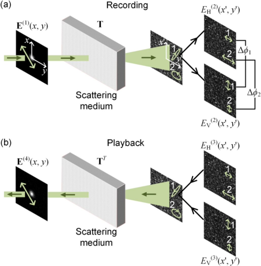
The process of full-polarization DOPC includes a recording step and a playback step (Fig. 1). In the recording step [Fig. 1(a)], as a concrete example, the incident light E(1)(x, y) is chosen to be a narrow collimated beam with a linear polarization. The light then passes through a scattering medium and evolves into a fully developed speckle pattern on the x’-y’ plane, with spatially non-uniform polarizations. In order to record the information about scattered light with various polarizations, the scattered light is decomposed into two components: EH(2)(x’, y’) and EV(2)(x’, y’), and both are recorded using phase shifting holography [22]. Here, “H” denotes the horizontal polarization and “V” denotes the vertical polarization, and they form complete orthogonal bases that can represent an arbitrary polarization state. This procedure is superior to existing DOPC approaches, where only one component (either “H” or “V”) is recorded and phase conjugated. In general, the speckle patterns corresponding to the two orthogonal polarizations bear little resemblance, and the polarizations at two arbitrary positions that are not within the same speckle grain, i.e., position 1 and position 2 [Fig. 1(a)], are completely uncorrelated in both amplitude ratio [|EH(2)(x1’, y1’)| / |EV(2)(x1’, y1’)| ≠ |EH(2)(x2’, y2’)| / |EV(2)(x2’, y2’)|] and relative phase [Δϕ1 = arg(EH(2)(x1’, y1’)/EV(2)(x1’, y1’)) ≠ Δϕ2 = arg(EH(2)(x2’, y2’)) / EV(2)(x2’, y2’))]. Here, |·| denotes taking the absolute value and arg(·) denotes taking the argument. Next, in the playback step [Fig. 1(b)], both OPC fields, with orthogonal polarizations, are produced and directed to the scattering medium. After they pass through the scattering medium, an output collimated beam that is phase-conjugated to the input beam is obtained.
Fig. 1.
Schematic of the processes in full-polarization DOPC. (a) In the recording step, the scattered light is recorded along the horizontal (H) and vertical (V) polarization directions. (b) In the playback step, OPC fields along the two orthogonal polarizations are produced and become phase-conjugated to the input light field after passing through the scattering medium.
We theoretically studied full-polarization DOPC by extending the existing scalar-field-based random matrix theory [23]. The input light field E(1)(x, y) is expressed as a Jones column vector concatenated by two components EH(1)(x, y) and EV(1)(x, y):
| (1) |
where each component comprises N spatial modes and is represented by an N×1 column vector. Since light transmission through the scattering medium and the subsequent optics is represented by a vector transmission matrix T [24, 25], the scattered light field on the SLM can be calculated as
| (2) |
Specifically, the vector transmission matrix T has the following form:
| (3) |
in which TAB (A, B = H, V) is an N-by-N matrix that connects the input field with B polarization and the scattered field with A polarization. By using singular value decomposition, each TAB can be further decomposed as TAB = UABtABVAB, where UAB and VAB are independent unitary matrices. Physically, UAB and VAB are transformation matrices converting between coordinates in Cartesian bases and eigenmode bases. tAB is a diagonal matrix with non-negative elements, and each element quantifies the transmission coefficient of each eigenmode. Thus, represents the average power transmission from polarization B to polarization A, where tr(·) denotes taking the trace of a matrix. In practice, only a fraction of the transmitted light is measured. Under this condition, the elements in each TAB can be approximated by the corresponding circular Gaussian distributions [23].Thus, for scattering media that are sufficiently thick to randomize the polarization state, TAB TAB† ≈ τAB I, where the symbol † represents the adjoint of a matrix and I is an identity matrix. The playback OPC field is phase-conjugated to the recorded field:
| (4) |
where the symbol * denotes complex conjugation. This field is sent back to pass through the scattering medium again. Finally, the output field after scattering is estimated by
| (5) |
where the scattering matrix is modeled by the transpose of the forward transmission matrix. Combining Eqs. (1)–(5) yields
| (6) |
Here, the first term on the right-hand side of Eq. (6) represents the phase-conjugated light, and the second term represents a background due to polarization coupling in partial OPC. Specifically, matrices with A, B, C = H, V and A ≠ C describe the mapping from the input light with A polarization to the scattered light with B polarization, followed by the mapping from the scattered light with B polarization to the output light with C polarization. The modulus of each element in MABC is O(1/N1/2). Physically, (τHH + τVH) and (τHV + τVV) are the total transmittances of the scattering medium when the incident light is purely horizontally polarized or purely vertically polarized, respectively. For most scattering media, these two values are very close. Therefore, E(4)(x, y) ≈ βE(1)(x, y)*, where β = (τHH + τVH) [or (τHV + τVV)] is a positive number. So, the full-polarization DOPC process faithfully produces the phase-conjugated field of the input light. However, if the DOPC process phase-conjugates scattered light only along the horizontal polarization direction (referred to as single-polarization DOPC), the output field is calculated as
| (7) |
Again, the first term on the right hand side of Eq. (7) represents the phase-conjugated light, while the second term corresponds to the background. In cases when τHH and τHV are not the same, the resultant field is not phase-conjugated to the input light field.
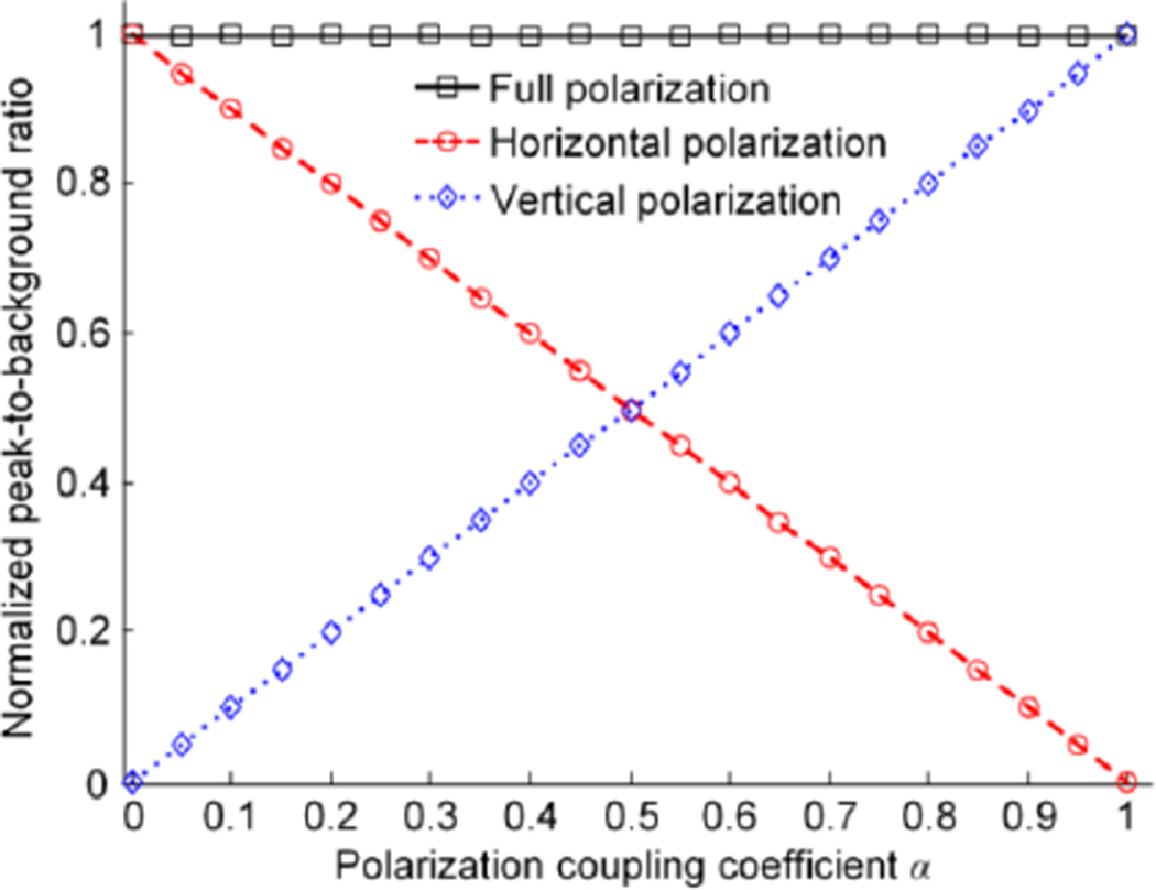
To compare the performance of full-polarization DOPC and single-polarization DOPC, we performed numerical simulations based on the above matrix analysis. In the simulation, N was set to be 2500, and the input light was chosen to be horizontally polarized with the central pixel being 1 for the electric field amplitude and the other pixels being 0. Each element in the transmission matrix TAB was drawn from a circular Gaussian distribution with mean μ = 0 and variance σ2 = τAB. Specifically, τHH was varied from 0 to 1, and we assumed τVV = τHH and τHV = τVH = 1 − τHH. Fig. 2 plots the peak-to-background ratio (PBR) normalized by N as a function of the polarization coupling coefficient α. PBR is defined as the ratio between the average intensities within and outside the targeted region of the phase-conjugated light; α quantifies the average energy transfer between the two orthogonal polarizations, and is defined as
| (8) |
Fig. 2 shows that the normalized PBRs for full-polarization DOPC are 1 for all values of α. In contrast, the normalized PBRs for single polarization DOPC change linearly with α. Such an observation is in accord with the theoretical expression of the normalized PBRs for single-polarization DOPC (= 1 − α and α for horizontal and vertical polarization DOPC respectively, which can be derived by following the same procedures in [23] but using the vector transmission matrix). Specifically, when α approaches 0.5, the PBRs achieved by horizontal-polarization DOPC and vertical-polarization DOPC are the same, and they are half of the PBR achieved by full polarization DOPC. An intuitive explanation is that in the full polarization scenario, the peak intensity is enhanced by a factor of 4 due to constructive interference, while the background is doubled by summing the background intensities corresponding to the two orthogonal polarizations. When α approaches 0 or 1, if the correct polarization state is not chosen to record and phase-conjugate the scattered light, the PBR of single polarization DOPC can become extremely low. In practice, α ~ 1 corresponds to a strongly birefringent sample with a small optical thickness, such as the retina of the eye [26]. Based on the above analysis, it is highly desired to develop a full-polarization DOPC system. The performance of such a system is not sensitive to the properties of the scattering media, and the system can always achieve a higher PBR than that achieved by single-polarization DOPC systems.
Fig. 2.
The normalized peak-to-background ratio as a function of the polarization coupling coefficient α for three different DOPC schemes. Discrete data points are from numerical simulation results, while the lines are plotted using analytical expressions.
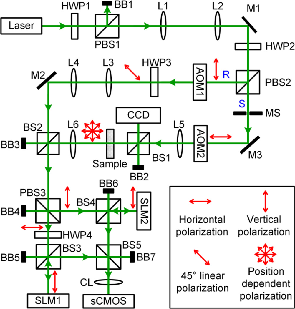
Based on the positive results from the numerical simulations, we developed a full-polarization DOPC system schematically shown in Fig. 3. In the phase recording step, the input light was split into a planar reference beam (R) and a sample beam (S) by a polarizing beamsplitter (PBS); R was vertically polarized and S was horizontally polarized. Each beam was subsequently modulated by an acoustooptic modulator to induce a 12 Hz frequency difference between R and S. The polarization direction of R was then rotated by a half wave plate (HWP) to 45 degrees. In the sample arm, S illuminated an ex vivo chicken breast tissue slice, and its polarization state became spatially inhomogeneous after tissue scattering. Then, the two beams were combined by a 50:50 beamspliter (BS) for interferometry. Since the scattered light took various polarization states, we used a PBS to spatially separate it into components with horizontal and vertical polarizations. Each component then impinged on the surface of an SLM whose pixels displayed all zeros at this step. Both SLMs had a resolution of 1920×1080 pixels, and were imaged onto a scientific complementary metal–oxide–semiconductor (sCMOS) camera (resolution 2560×2160) by a camera lens. Each pixel in the SLMs corresponded to one pixel on the sCMOS camera. To use a single camera to image both SLMs simultaneously, the SLMs were rotated 90 degrees clockwise. Since both SLMs could modulate light only with vertical polarization, HWP4 was inserted before SLM1 to rotate the polarization of the light to vertical direction. The phase maps corresponding to the horizontally polarized scattered light and the vertically polarized scattered light were measured using phase-shifting holography [17, 22], made possible by making the camera run at a frame rate of 48 Hz (=4×12 Hz).
Fig. 3.
Schematic of the full-polarization DOPC set-up. Polarization states are indicated by the red arrows. AOM, acousto-optic modulator (AOM-505AF1, IntraAction); BB, beam block; BS, beamsplitter; CCD, CCD camera (GS3-U3-50S5M-C, Point Grey; pixel size 3.45 µm); CL, camera lens; HWP, half wave plate; L, lens; Laser, Verdi V5, Coherent, 532 nm; M, mirror; MS, mechanical shutter; PBS, polarizing beamspliter; R, reference beam; S, sample beam; sCMOS, scientific CMOS camera (pco.edge 5.5, pco; pixel size 6.5 µm); SLM, spatial light modulator (Pluto NIR-II, Holoeye; pixel size 8 µm).
In the playback step, the conjugate phase maps were displayed on the respective SLMs. An experimentally determined constant phase offset was added to one of the phase maps to compensate for the difference between the path length from PBS3 to SLM1 and from PBS3 to SLM2. The sample beam was blocked by a mechanical shutter in this step, and the planar reference beam illuminated the two SLMs to acquire the conjugate phase map. The two branches of phase conjugated light were then combined by PBS3 and were directed to the scattering sample. After they passed through the sample, a bright focus was formed on the focal plane of lens L5. To observe the focus, a 10:90 BS was inserted to create a copy of the focus, which was captured by a charge-coupled device (CCD) camera.
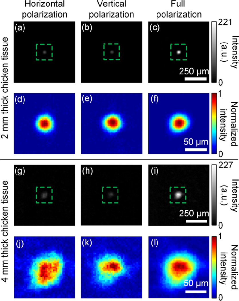
In our experiment, we used 2 mm and 4 mm thick chicken breast tissue as scattering samples, and α was close to 0.5 for both samples, which is expected for thick scattering media. Images of the focal spots achieved by single-polarization DOPC and full-polarization DOPC are shown in Fig. 4. Specifically, Fig. 4(a), (b), and (c) show the imaged foci when only horizontal polarization, only vertical polarization, and full polarization were used for DOPC through 2 mm thick chicken breast tissue. All three images are shown using the same intensity scale. The peak intensity of the focus achieved by full-polarization DOPC is ~ 4 times as high as that achieved by single-polarization DOPC. Moreover, the PBRs for the three images are 141, 135, and 262, respectively. This result illustrates that the PBR achieved by full-polarization DOPC is roughly twice that achieved by single-polarization DOPC, which is in good agreement with our theoretical predictions. To better visualize the shape of the focus, each image is zoomed in and is normalized by its own peak intensity, as shown in Fig. 4 (d), (e), and (f). It can be seen that all three foci maintain nearly circular shapes, which shows that when the sample is not too thick, single-polarization DOPC can still achieve high OPC fidelity. For the 4 mm thick chicken tissue, the images of the foci achieved by horizontal polarization, vertical polarization, and full polarization DOPC are shown in Fig. 4 (g), (h), and (i), respectively. Again, the intensity of the focus achieved by full-polarization DOPC is roughly 4 times as high as that achieved by single-polarization DOPC. Due to the increased thickness, the PBRs for the three images are lower and are calculated to be 21, 18, and 37. However, full-polarization DOPC still approximately doubles the PBR achieved by single-polarization DOPC. Fig. 4 (j), (k), and (l) show the enlarged images of the foci after normalization by their own peak intensities. Among all three foci, the one achieved by full-polarization DOPC has a nearly circular shape that most closely resembles the shape of the input focus. Such a result indicates that when the sample is thick, full-polarization DOPC can achieve higher OPC fidelity than that achieved by single-polarization DOPC [9]. We note that the increased size of the foci for 4 mm thick chicken tissue is due to different experimental conditions.
Fig. 4.
Images of the foci achieved by single-polarization and full-polarization DOPC. (a)–(c) Images of the foci through 2 mm thick chicken breast tissue when only horizontal-polarization, only vertical-polarization, and full-polarization DOPC were employed. (d)–(f) Enlarged images of (a)–(c). To better visualize the shape of the focus, each image is normalized by its own peak intensity. (g)–(i) Images of the foci through 4 mm thick chicken breast tissue when only horizontal-polarization, only vertical-polarization, and full-polarization DOPC were employed. (j)–(l) Enlarged images of (g)–(i). Again, to better visualize the shape of the focus, each image is normalized by its own peak intensity.
Here, we briefly discuss the polarization states of the OPC field in our experiments. Currently, the two SLMs in the set-up modulate only the phase but not the amplitude of light. Thus, the SLM-generated OPC field before illuminating the sample does not have the same polarization as that of the scattered light. Nonetheless, compared with the ideal case when both phase and amplitude are modulated, due to the scrambling nature of the thick scattering medium, the phase-modulated light still constructively interferes in the same polarization state as that of the recording-phase input light (though the amplitude is reduced), while there is no constructive interference in the orthogonal polarization state. Thus, after the SLM-generated OPC field passes through the scattering medium, the polarization of the electric field at the focus is approximately the same as that of the input field. In our experiments, the input electric field at the focus was set to be horizontally polarized. Using a polarizer, we confirmed that the electric field at the focus achieved by full-polarization DOPC was also horizontally polarized.
In conclusion, we developed the first DOPC system that can record and phase-conjugate the scattered light with various polarization states. When the scattering sample is optically thick, our system doubles the PBR achieved by single-polarization DOPC systems, improves the OPC fidelity, and maintains the polarization of the input light field. The method described here can be easily applied to existing DOPC systems to improve their performance.
Acknowledgments
We thank Jinyang Liang for helpful discussions, and James Ballard for proofreading the manuscript.
Funding. National Institutes of Health [DP1 EB016986 (NIH Director’s Pioneer Award) and R01 CA186567 (NIH Director’s Transformative Research Award)].
References
- 1.Ntziachristos V. Going deeper than microscopy: the optical imaging frontier in biology. Nat Methods. 2010;7:603–614. doi: 10.1038/nmeth.1483. [DOI] [PubMed] [Google Scholar]
- 2.Liu Y, Zhang C, Wang LV. Effects of light scattering on optical-resolution photoacoustic microscopy. J Biomed Opt. 2012;17:126014–126019. doi: 10.1117/1.JBO.17.12.126014. [DOI] [PMC free article] [PubMed] [Google Scholar]
- 3.Wang LV, Wu H. Biomedical optics : principles and imaging. Hoboken, N.J: Wiley-Interscience; 2007. p. xiv.p. 362. [Google Scholar]
- 4.Vellekoop IM, Mosk AP. Focusing coherent light through opaque strongly scattering media. Opt Lett. 2007;32:2309–2311. doi: 10.1364/ol.32.002309. [DOI] [PubMed] [Google Scholar]
- 5.Cui M. A high speed wavefront determination method based on spatial frequency modulations for focusing light through random scattering media. Opt Express. 2011;19:2989–2995. doi: 10.1364/OE.19.002989. [DOI] [PubMed] [Google Scholar]
- 6.Lai P, Wang L, Tay JW, Wang LV. Photoacoustically guided wavefront shaping for enhanced optical focusing in scattering media. Nat Photon. 2015;9:126–132. doi: 10.1038/nphoton.2014.322. [DOI] [PMC free article] [PubMed] [Google Scholar]
- 7.Popoff S, Lerosey G, Carminati R, Fink M, Boccara A, Gigan S. Measuring the transmission matrix in optics: an approach to the study and control of light propagation in disordered media. Phys Rev Lett. 2010;104:100601. doi: 10.1103/PhysRevLett.104.100601. [DOI] [PubMed] [Google Scholar]
- 8.Yaqoob Z, Psaltis D, Feld MS, Yang C. Optical phase conjugation for turbidity suppression in biological samples. Nat Photonics. 2008;2:110–115. doi: 10.1038/nphoton.2007.297. [DOI] [PMC free article] [PubMed] [Google Scholar]
- 9.Beckwith PH, McMichael I, Yeh P. Image distortion in multimode fibers and restoration by polarization-preserving phase conjugation. Opt Lett. 1987;12:510–512. doi: 10.1364/ol.12.000510. [DOI] [PubMed] [Google Scholar]
- 10.Xu X, Liu H, Wang LV. Time-reversed ultrasonically encoded optical focusing into scattering media. Nat Photonics. 2011;5:154–157. doi: 10.1038/nphoton.2010.306. [DOI] [PMC free article] [PubMed] [Google Scholar]
- 11.Liu Y, Lai P, Ma C, Xu X, Grabar AA, Wang LV. Optical focusing deep inside dynamic scattering media with near-infrared time-reversed ultrasonically encoded (TRUE) light. Nat Commun. 2015;6 doi: 10.1038/ncomms6904. [DOI] [PMC free article] [PubMed] [Google Scholar]
- 12.Cui M, Yang C. Implementation of a digital optical phase conjugation system and its application to study the robustness of turbidity suppression by phase conjugation. Opt Express. 2010;18:3444–3455. doi: 10.1364/OE.18.003444. [DOI] [PMC free article] [PubMed] [Google Scholar]
- 13.Hsieh C-L, Pu Y, Grange R, Laporte G, Psaltis D. Imaging through turbid layers by scanning the phase conjugated second harmonic radiation from a nanoparticle. Opt Express. 2010;18:20723–20731. doi: 10.1364/OE.18.020723. [DOI] [PubMed] [Google Scholar]
- 14.Hillman TR, Yamauchi T, Choi W, Dasari RR, Feld MS, Park Y, Yaqoob Z. Digital optical phase conjugation for delivering two-dimensional images through turbid media. Scientific reports. 2013;3:1909. doi: 10.1038/srep01909. [DOI] [PMC free article] [PubMed] [Google Scholar]
- 15.Wang D, Zhou EH, Brake J, Ruan H, Jang M, Yang C. Focusing through dynamic tissue with millisecond digital optical phase conjugation. Optica. 2015;2:728–735. doi: 10.1364/OPTICA.2.000728. [DOI] [PMC free article] [PubMed] [Google Scholar]
- 16.Wang YM, Judkewitz B, DiMarzio CA, Yang C. Deep-tissue focal fluorescence imaging with digitally time-reversed ultrasound-encoded light. Nat Commun. 2012;3:928. doi: 10.1038/ncomms1925. [DOI] [PMC free article] [PubMed] [Google Scholar]
- 17.Si K, Fiolka R, Cui M. Fluorescence imaging beyond the ballistic regime by ultrasound-pulse-guided digital phase conjugation. Nat Photon. 2012;6:657–661. doi: 10.1038/nphoton.2012.205. [DOI] [PMC free article] [PubMed] [Google Scholar]
- 18.Judkewitz B, Wang YM, Horstmeyer R, Mathy A, Yang C. Speckle-scale focusing in the diffusive regime with time-reversal of variance-encoded light (TROVE) Nat Photonics. 2013;7:300–305. doi: 10.1038/nphoton.2013.31. [DOI] [PMC free article] [PubMed] [Google Scholar]
- 19.Ma C, Xu X, Liu Y, Wang LV. Time-reversed adapted-perturbation (TRAP) optical focusing onto dynamic objects inside scattering media. Nat Photon. 2014;8:931–936. doi: 10.1038/nphoton.2014.251. [DOI] [PMC free article] [PubMed] [Google Scholar]
- 20.Zhou EH, Ruan H, Yang C, Judkewitz B. Focusing on moving targets through scattering samples. Optica. 2014;1:227–232. doi: 10.1364/OPTICA.1.000227. [DOI] [PMC free article] [PubMed] [Google Scholar]
- 21.Ma C, Zhou F, Liu Y, Wang LV. Single-exposure optical focusing inside scattering media using binarized time-reversed adapted perturbation. Optica. 2015;2:869–876. doi: 10.1364/OPTICA.2.000869. [DOI] [PMC free article] [PubMed] [Google Scholar]
- 22.Yamaguchi I, Zhang T. Phase-shifting digital holography. Opt Lett. 1997;22:1268–1270. doi: 10.1364/ol.22.001268. [DOI] [PubMed] [Google Scholar]
- 23.Vellekoop IM. PhD thesis. 2008. Controlling the propagation of light in disordered scattering media. [Google Scholar]
- 24.Tripathi S, Paxman R, Bifano T, Toussaint KC. Vector transmission matrix for the polarization behavior of light propagation in highly scattering media. Opt Express. 2012;20:16067–16076. doi: 10.1364/OE.20.016067. [DOI] [PubMed] [Google Scholar]
- 25.Park J, Park J-H, Yu H, Park Y. Focusing through turbid media by polarization modulation. Opt Lett. 2015;40:1667–1670. doi: 10.1364/OL.40.001667. [DOI] [PubMed] [Google Scholar]
- 26.Cense B, Chen TC, Park BH, Pierce MC, de Boer JF. Thickness and Birefringence of Healthy Retinal Nerve Fiber Layer Tissue Measured with Polarization-Sensitive Optical Coherence Tomography. Investigative Ophthalmology & Visual Science. 2004;45:2606–2612. doi: 10.1167/iovs.03-1160. [DOI] [PubMed] [Google Scholar]


